
Home › Sample questions › Class 1 Electrician 第一種電気工事士 (written exam)
Class 1 Electrician 第一種電気工事士 practice test with answers – free sample questions
第一種電気工事士(学科試験)
10 sample questions in the real exam format, with furigana, English translation, answers and explanations. Tap "Show answer" under each question. For the full question bank and realistic mock exams, open the free app.
Question 1
静電容量 C₁ = 20 μF と C₂ = 30 μF の2個のコンデンサを直列に接続し、その両端に 100 V の直流電圧を加えた。この回路全体に蓄えられる静電エネルギー W[J]の値はいくらか。
Two capacitors with capacitances C₁ = 20 μF and C₂ = 30 μF are connected in series across a 100 V DC voltage source. What is the total electrostatic energy W (J) stored in this series capacitor circuit?
- A. 0.06 J
- B. 0.12 J
- C. 0.25 J
- D. 0.50 J
Show answer
Correct answer: A
For two capacitors C₁ = 20 μF and C₂ = 30 μF in series, the equivalent capacitance is C = (20 × 30) ÷ (20 + 30) = 600 ÷ 50 = 12 μF = 12 × 10⁻⁶ F. The electrostatic energy stored at 100 V is W = 0.5 × C × V² = 0.5 × 12 × 10⁻⁶ × 100² = 0.06 J. Value 0.12 J omits the 0.5 factor; 0.25 J treats the capacitors as parallel (50 μF); 0.50 J makes both errors.
💡 Series capacitance C = (C₁ × C₂) ÷ (C₁ + C₂) = 12 μF. Electrostatic energy W = 0.5 × C × V² at 100 V equals 0.06 J.
| Word | Meaning |
|---|---|
| 静電容量 | capacitance |
| 静電エネルギー | electrostatic energy |
| 直列接続 | series connection |
Question 2
自己インダクタンス L = 40 mH のコイルに直流電流 I = 5 A を流したとき、このコイルに蓄えられる電磁エネルギー W[J]と、電流を 0.1 秒間で 5 A から 0 A まで一様に減少させたときに発生する自己誘導起電力の大きさ e[V]の組合せとして、正しいものはどれか。
When a DC current of I = 5 A flows through a coil with self-inductance L = 40 mH, which combination correctly gives the stored electromagnetic energy W (J) and the magnitude of the self-induced EMF e (V) generated when the current decreases uniformly from 5 A to 0 A in 0.1 seconds?
- A. W = 0.5 J、e = 2 V
W = 0.5 J, e = 2.0 V - B. W = 0.5 J、e = 0.2 V
W = 0.5 J, e = 0.2 V - C. W = 1.0 J、e = 2.0 V
W = 1.0 J, e = 2.0 V - D. W = 0.1 J、e = 20 V
W = 0.1 J, e = 20 V
Show answer
Correct answer: A
Converting L = 40 mH = 0.04 H, the stored magnetic energy is W = 0.5 × L × I² = 0.5 × 0.04 × 5² = 0.5 J. The magnitude of the self-induced EMF when current changes by ΔI = 5 A in Δt = 0.1 s is e = L × (ΔI ÷ Δt) = 0.04 × (5 ÷ 0.1) = 2.0 V.
| Word | Meaning |
|---|---|
| 自己インダクタンス | self-inductance |
| 電磁エネルギー | electromagnetic energy |
| 自己誘導起電力 | self-induced electromotive force |
Question 3
図のような2個の直流電源 E₁ = 24 V、E₂ = 8 V を含む直流回路において、中央の節点 a−b 間に接続された抵抗 R₃ = 6 Ω に流れる電流 I₃[A]の値はいくらか。
In the DC circuit shown in the figure with two DC sources E₁ = 24 V and E₂ = 8 V, what is the current I₃ (A) flowing through the center resistor R₃ = 6 Ω connected between nodes a and b?
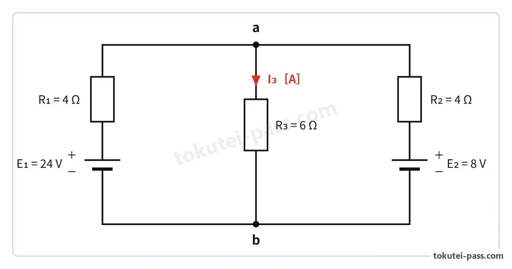
- A. 1.5 A
- B. 2.0 A
- C. 2.5 A
- D. 3.0 A
Show answer
Correct answer: B
Let V_ab be the voltage between nodes a and b. By Kirchhoff's current law at node a, I₁ + I₂ = I₃, so (24 − V_ab) ÷ 4 + (8 − V_ab) ÷ 4 = V_ab ÷ 6. Multiplying by 12 gives 3(24 − V_ab) + 3(8 − V_ab) = 2V_ab, or 96 = 8V_ab, which yields V_ab = 12 V. Thus, the current through center resistor R₃ = 6 Ω is I₃ = 12 V ÷ 6 Ω = 2.0 A.
💡 Use node voltage V_ab with Kirchhoff's current law at node a: (24 − V_ab)/4 + (8 − V_ab)/4 = V_ab/6 gives V_ab = 12 V and I₃ = 2.0 A.
| Word | Meaning |
|---|---|
| キルヒホッフの法則 | Kirchhoff's laws |
| 節点 | node (junction) |
| 閉回路 | closed loop |
Question 4
周期 T = 20 ms(ミリ秒)、実効値 100 V の正弦波交流電圧がある。この交流電圧の周波数 f[Hz]と角周波数 ω[rad/s]の組合せとして、正しいものはどれか。ただし、円周率 π = 3.14 とする。
A sinusoidal AC voltage has a period of T = 20 ms (milliseconds) and an RMS value of 100 V. Which combination correctly gives its frequency f (Hz) and angular frequency ω (rad/s)? Use π = 3.14.
- A. f = 60 Hz、ω = 377 rad/s
f = 60 Hz, ω = 377 rad/s - B. f = 50 Hz、ω = 157 rad/s
f = 50 Hz, ω = 157 rad/s - C. f = 50 Hz、ω = 314 rad/s
f = 50 Hz, ω = 314 rad/s - D. f = 20 Hz、ω = 126 rad/s
f = 20 Hz, ω = 126 rad/s
Show answer
Correct answer: C
Since period T = 20 ms = 0.02 s, the frequency is f = 1 ÷ T = 1 ÷ 0.02 = 50 Hz. The angular frequency is ω = 2πf = 2 × 3.14 × 50 = 314 rad/s.
| Word | Meaning |
|---|---|
| 正弦波交流 | sinusoidal alternating current |
| 周期 | period |
| 角周波数 | angular frequency |
Question 5
単相3線式 200/100 V の配電線路において、上側の電圧線と中性線との間に遅れ力率 cosθ₁ = 0.5、電流 I₁ = 20 A の誘導性負荷を接続し、下側の電圧線と中性線との間に力率 cosθ₂ = 1.0、電流 I₂ = 20 A の抵抗負荷を接続した。このとき、中性線に流れる電流 I_N[A]の値はいくらか。
In a single-phase 3-wire 200/100 V distribution line, an inductive load with lagging power factor cosθ₁ = 0.5 and current I₁ = 20 A is connected between the upper line and the neutral wire, while a resistive load with cosθ₂ = 1.0 and current I₂ = 20 A is connected between the lower line and the neutral wire. What is the neutral wire current I_N (A)?
- A. 0 A
- B. 10 A
- C. 14.1 A
- D. 20 A
Show answer
Correct answer: D
Resolving each current into in-phase and quadrature components: I₁ has active component I₁p = 20 × 0.5 = 10 A and reactive component I₁q = 20 × (√3 ÷ 2) = 10√3 A, whereas resistive load I₂ has I₂p = 20 A and I₂q = 0 A. In the neutral wire, active components subtract: I_N = √((10 − 20)² + (10√3 − 0)²) = √(100 + 300) = √400 = 20 A.
💡 In a single-phase 3-wire line with lagging power factor cosθ₁ = 0.5 (60°) and cosθ₂ = 1.0, neutral wire current I_N = √((I₁p − I₂p)² + I₁q²) = 20 A.
| Word | Meaning |
|---|---|
| 単相3線式 | single-phase 3-wire system |
| 中性線 | neutral wire |
| 遅れ力率 | lagging power factor |
Question 6
単相2線式配電線路において、電源点 A の電圧が 108 V である。点 A から中間点 B までの電線1線あたりの抵抗が 0.1 Ω、中間点 B から末端 C までの電線1線あたりの抵抗が 0.15 Ω であるとき、点 B で 20 A、末端 C で 10 A の抵抗負荷(力率 100 %)に給電したときの末端 C の電圧 V_C[V]はいくらか。ただし、線路のリアクタンスは無視する。
In a single-phase 2-wire distribution line, the sending-end voltage at point A is 108 V. The resistance per wire is 0.1 Ω between point A and midpoint B, and 0.15 Ω between midpoint B and end point C. When resistive loads (100% power factor) draw 20 A at point B and 10 A at point C, what is the terminal voltage V_C (V) at point C? Neglect line reactance.
- A. 103.5 V
- B. 102 V
- C. 99 V
- D. 96 V
Show answer
Correct answer: C
The current in section A−B is the sum of both loads: I_AB = 20 + 10 = 30 A, while the current in section B−C is I_BC = 10 A. For a single-phase 2-wire line, the voltage drop in A−B is ΔV_AB = 2 × 0.1 × 30 = 6.0 V, and in B−C is ΔV_BC = 2 × 0.15 × 10 = 3.0 V. Thus, V_C = 108 − (6.0 + 3.0) = 99.0 V.
| Word | Meaning |
|---|---|
| 負荷電流 | load current |
| 電圧降下 | voltage drop |
| 線路抵抗 | line resistance |
Question 7
単相3線式配電線路において、上下の電圧線と中性線との間にそれぞれ消費電力 1.6 kW、端子電圧 100 V、遅れ力率 0.8 の平衡負荷が接続されている。電線1線あたりの抵抗が 0.15 Ω であるとき、この配電線路全体の電力損失 P_l[W]はいくらか。
In a single-phase 3-wire distribution line, balanced loads each consuming 1.6 kW at a terminal voltage of 100 V and a lagging power factor of 0.8 are connected between each outer wire and the neutral wire. If the resistance per wire is 0.15 Ω, what is the total line power loss P_l (W)?
- A. 60 W
- B. 76.8 W
- C. 120 W
- D. 180 W
Show answer
Correct answer: C
The current in each outer wire is I = P ÷ (V × cosθ) = 1600 W ÷ (100 V × 0.8) = 20 A. Because the loads are balanced, the neutral current is 0 A. Thus, the total line power loss in the two outer wires is P_l = 2 × I² × r = 2 × 20² × 0.15 = 120 W.
| Word | Meaning |
|---|---|
| 電力損失 | power loss |
| 平衡負荷 | balanced load |
| 消費電力 | power consumption |
Question 8
単相変圧器の二次側に、有効電力 P₁ = 16 kW、遅れ無効電力 Q₁ = 16 kvar の誘導性負荷が接続されている。これに有効電力 P₂ = 14 kW、力率 100 % の抵抗負荷を並列に追加したとき、変圧器が供給する合成皮相電力 S[kVA]の値はいくらか。
An inductive load with active power P₁ = 16 kW and lagging reactive power Q₁ = 16 kvar is connected to the secondary of a single-phase transformer. When a resistive load with active power P₂ = 14 kW (100% power factor) is added in parallel, what is the combined apparent power S (kVA) supplied by the transformer?
- A. 30 kVA
- B. 34 kVA
- C. 36.6 kVA
- D. 46 kVA
Show answer
Correct answer: B
Because the resistive load has 100% power factor, its reactive power is Q₂ = 0 kvar. The total active power is P = P₁ + P₂ = 16 + 14 = 30 kW, and the total reactive power is Q = 16 + 0 = 16 kvar. Therefore, the combined apparent power is S = √(P² + Q²) = √(30² + 16²) = √(900 + 256) = √1156 = 34 kVA.
| Word | Meaning |
|---|---|
| 合成皮相電力 | combined apparent power |
| 有効電力 | active power |
| 無効電力 | reactive power |
Question 9
極数 4、定格周波数 60 Hz の三相かご形誘導電動機が、滑り s = 5 % で運転されているとき、回転速度 N[min⁻¹]はいくらか。
When a 4-pole, 60 Hz three-phase squirrel-cage induction motor operates at a slip of s = 5%, what is its rotational speed N (min⁻¹)?
- A. 1 425 min⁻¹
- B. 1 500 min⁻¹
- C. 1 710 min⁻¹
- D. 1 800 min⁻¹
Show answer
Correct answer: C
The synchronous speed of a 4-pole motor at 60 Hz is N_s = (120 × f) ÷ p = (120 × 60) ÷ 4 = 1800 min⁻¹. At a slip of s = 5% = 0.05, the rotor speed is N = N_s × (1 − s) = 1800 × (1 − 0.05) = 1710 min⁻¹.
| Word | Meaning |
|---|---|
| 同期速度 | synchronous speed |
| 滑り | slip |
| 回転速度 | rotational speed |
Question 10
高圧受電設備に用いられる変圧器の鉄損、銅損および最大効率条件についての記述のうち、誤っているものはどれか。
Which of the following statements regarding transformer losses and efficiency is INCORRECT?
- A. 無負荷損の大部分は鉄損であり、ヒステリシス損と渦電流損からなる。
No-load loss consists mainly of iron loss, which is the sum of hysteresis loss and eddy-current loss. - B. 負荷損の大部分は巻線の抵抗による銅損であり、負荷電流の2乗に比例する。
Load loss consists mainly of copper loss in the winding resistance and is proportional to the square of the load current. - C. 定格電圧および定格周波数のもとでは、鉄損は負荷の大きさにかかわらずほぼ一定である。
At rated voltage and rated frequency, iron loss remains nearly constant regardless of the load magnitude. - D. 変圧器の効率が最大となるのは、銅損がゼロで鉄損のみとなる無負荷運転時である。
Transformer efficiency reaches its maximum during no-load operation when copper loss is zero and only iron loss exists.
Show answer
Correct answer: D
At no load, output power is zero so efficiency is 0%. A transformer achieves maximum efficiency at the load where variable copper loss equals constant iron loss (copper loss = iron loss).
| Word | Meaning |
|---|---|
| 鉄損 | iron loss (core loss) |
| 銅損 | copper loss (winding loss) |
| 最大効率 | maximum efficiency |