Rebar Work (Fabrication, Assembly, Pressure Welding, and Rebar Inspection)
鉄筋施工(鉄筋加工・組立・圧接・配筋検査)
Construction · 建設分野 · Written by Tokutei Pass based on the official study texts; not copied verbatim.
鉄筋材料の種類・JIS規格と圧延マーク・保管管理
Types of Reinforcing Bars, JIS Standards, Rolled Identification Marks, and Storage Control
鉄筋コンクリート(RC)は、圧縮力に強いが引張力に弱いコンクリートと、引張力に強い鉄筋を一体的に組み合わせた構造です。表面に突起がない「丸鋼(SR)」と、コンクリートとの付着力を高める突起がある「異形棒鋼(SD)」があります。
Reinforced concrete (RC) combines concrete, which is strong in compression but weak in tension, with steel reinforcing bars, which have high tensile strength. Bars are classified into plain round bars (SR) without surface lugs and deformed bars (SD) with protrusions that increase bond with concrete.
異形棒鋼の表面で軸方向に連続する突起を「リブ」、軸と交差する突起を「節」といい、呼び名は公称直径(mm)に近い数値で「D10・D13・D16・D19・D22・D25・D29・D32・D35・D38・D41」などと表します。
On a deformed steel bar, the continuous longitudinal protrusion along the bar axis is called a 'rib', and the transverse protrusions are called 'lugs (nodes / Fushi)'. Nominal sizes correspond to approximate nominal diameters in millimeters: D10, D13, D16, D19, D22, D25, D29, D32, D35, D38, and D41.
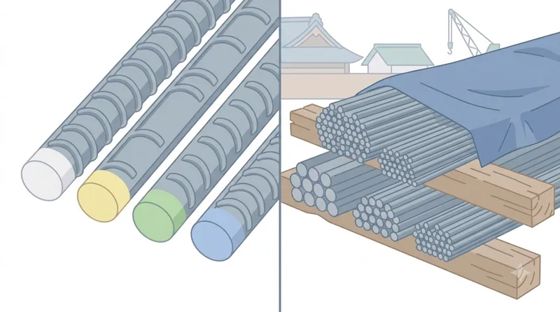
鋼種の記号「SD295A・SD295B・SD345・SD390・SD490」の数字は降伏点(耐力)の下限値(N/mm²)を示します。端面塗色と圧延マークは、SD295Bが白(突起なし)、SD345が黄(突起1個・)、SD390が緑(突起2個・・)、SD490が青(突起3個・・・)です。
The numbers in steel grade symbols 'SD295A, SD295B, SD345, SD390, SD490' indicate the lower limit of yield point in N/mm². Under JIS G 3112, end-face paint colors and rolled grade marks are: SD295A = uncolored (no dot), SD295B = white (no dot), SD345 = yellow (1 dot ・), SD390 = green (2 dots ・・), and SD490 = blue (3 dots ・・・).
また搬入時には「ミルシート(鋼材検査証明書)」により化学成分や機械的性質がJIS規格に適合しているかを照合します。鉄筋は地面に直接置かず「りん木(まくら木)」の上に鋼種・径別に整理し、シートで覆って保管します。
Upon delivery to the site, the 'mill sheet (inspection certificate)' is checked to verify chemical composition and mechanical properties against JIS standards. Bars must be stored off the ground on timber sleepers (dunnage), sorted by grade and size, and covered with protective sheets.
Key points
- 異形棒鋼(SD)は軸方向の「リブ」と交差方向の「節」でコンクリートとの付着力を高め、数字は降伏点の下限値(N/mm²)を示す
Deformed bars (SD) improve concrete bond via longitudinal 'ribs' and transverse 'lugs', and the grade number indicates minimum yield strength (N/mm²) - 鋼種の識別(JIS G 3112)は、SD295B=白(突起なし)、SD345=黄(突起1個・)、SD390=緑(突起2個・・)、SD490=青(突起3個・・・)である
Grade identification (JIS G 3112): SD295B = white (no dot), SD345 = yellow (1 dot ・), SD390 = green (2 dots ・・), SD490 = blue (3 dots ・・・) - 搬入時は「ミルシート(鋼材検査証明書)」で品質を確認し、泥やさびを防ぐため「りん木(まくら木)」を敷いてシートを掛けて保管する
Verify quality with the 'mill sheet' upon delivery, and support bars on timber sleepers off the bare ground covered with sheets to prevent mud and rust
| Word | Meaning |
|---|---|
| 異形棒鋼(リブ・節) | deformed steel bar (rib and lug) |
| 降伏点の下限値 | lower limit of yield point |
| 圧延マーク・端面塗色 | rolled mark and end-face color coding |
| ミルシート(鋼材検査証明書) | mill test certificate (mill sheet) |
| りん木(まくら木) | timber sleeper / dunnage (Makuragi / Ringi) |
構造部材の各部鉄筋名称と配筋図の記号
Names of Reinforcing Bars in Structural Members and Rebar Drawing Symbols
建築構造図の部材記号では、基礎を「F」、基礎梁を「FG」、柱を「C」、大梁を「G」、小梁を「B」、床スラブを「S」、壁を「W」と表します。また配筋記号の「4-D25」はD25を4本、「D10@200」はD10を200mmピッチ(間隔)で配置することを意味します。
In architectural structural drawings, member symbols are: F = Footing, FG = Footing Girder, C = Column, G = Girder (main beam), B = secondary Beam, S = Slab, and W = Wall. In bar notation, '4-D25' means four D25 bars, and 'D10@200' means D10 bars placed at a 200 mm center-to-center pitch.
「柱」では、鉛直方向の力と曲げモーメントを支える縦方向の「柱主筋」の周囲に、せん断破壊と主筋の座屈を防ぐ「帯筋(フープ)」を巻きます。内部の主筋を拘束する副帯筋を「中子筋」といいます。
In a 'column', lateral shear reinforcement called 'column hoops (Obikin / hoops)' is wrapped around vertical 'column main bars' to prevent shear failure and buckling of the main bars. Internal supplementary ties restraining inner main bars are called 'sub-ties (Nakagokin)'.
「梁」では、上側の「上端筋」と下側の「下端筋」の周囲にせん断補強筋の「あばら筋(スターラップ)」を巻きます。梁のせいが高いときは側面に「腹筋」と「幅止め筋」を入れ、1段目と2段目の主筋(二段筋)の間には「まくら筋」を挟みます。
In a 'beam', shear reinforcement called 'stirrups (Abarakin)' is wrapped around the 'top main bars' and 'bottom main bars'. Deep beams also have horizontal 'web bars (Harakin)' and 'cross ties (Habadomekin)' along the side faces, and short 'spacer bars (Makurakin)' inserted between first-layer and second-layer main bars.
「床スラブ」では、曲げ応力が大きい「短辺方向」に主筋を、「長辺方向」に配力筋を配置します。長方形スラブの下筋では短辺方向の主筋を一番下(外側)に配筋し、上筋では短辺方向の主筋を一番上(外側)に配筋します。
In a 'floor slab', 'main bars' are placed in the short-span direction where bending stress is greater, and 'distribution bars' in the long-span direction. In the bottom layer of a rectangular slab, short-span main bars are placed on the bottom (outermost), while in the top layer they are placed on top (outermost).
Key points
- 構造図記号はC=柱、G=大梁、FG=基礎梁、B=小梁、S=スラブ、W=壁であり、「@200」は200mm間隔(ピッチ)を表す
Structural symbols: C = Column, G = Girder, FG = Footing Girder, B = Beam, S = Slab, W = Wall; '@200' denotes a 200 mm bar spacing (pitch) - 柱のせん断補強筋は「帯筋(フープ)」、梁のせん断補強筋は「あばら筋(スターラップ)」といい、二段筋の間隔保持には「まくら筋」を入れる
Column shear reinforcement is called 'hoops (Obikin)', beam shear reinforcement is called 'stirrups (Abarakin)', and bars separating first- and second-tier main bars are called 'spacer bars (Makurakin)' - 床スラブは「短辺方向」が主筋、「長辺方向」が配力筋であり、下筋は短辺方向の主筋を下側(外側)に配置する
In floor slabs, main bars run in the 'short-span direction' and distribution bars in the 'long-span direction', with short-span bottom bars placed underneath (outermost)
| Word | Meaning |
|---|---|
| 帯筋(フープ)・あばら筋(スターラップ) | column hoop (Obikin) and beam stirrup (Abarakin) |
| 腹筋・幅止め筋 | beam web bar (Harakin) and cross tie (Habadomekin) |
| 二段筋・まくら筋 | second-tier bar (Nidankin) and layer spacer bar (Makurakin) |
| 短辺方向(主筋)・長辺方向(配力筋) | short-span direction (main bar) and long-span direction (distribution bar) |
かぶり厚さの規定とスペーサーの種類・配置基準
Concrete Cover Regulations and Types and Placement Standards of Spacers
「かぶり厚さ」とは、最外縁の鉄筋(柱の帯筋や梁のあばら筋など)の表面からコンクリート表面までの最短距離のことです。コンクリートのアルカリ性で鉄筋の腐食(さび)を防ぎ、火災時の耐火性と流動性・付着力を確保する重要な役割があります。
'Concrete cover thickness (Kaburi atsusa)' is the shortest distance from the outer surface of the outermost reinforcing bar (such as a column hoop or beam stirrup) to the concrete surface. It protects bars against corrosion via concrete alkalinity, ensures fire resistance, and secures bond strength.
建築基準法施行令第79条による「最小かぶり厚さ」は、直接土に接しない屋内の「屋根版・床版・非耐力壁」で2cm(20mm)以上、屋内の「耐力壁・柱・梁」で3cm(30mm)以上と定められています。
Under Article 79 of the Building Standard Law Enforcement Order, the 'minimum concrete cover' for indoor members not in contact with soil is 2 cm (20 mm) or more for roof slabs, floor slabs, and non-bearing walls, and 3 cm (30 mm) or more for indoor bearing walls, columns, and beams.
一方、直接土に接する「壁・柱・床・梁」では4cm(40mm)以上、「基礎(捨てコンクリートを除く)」では6cm(60mm)以上が必要です。現場では施工誤差を見込んで最小値に10mm程度を加えた「設計かぶり厚さ」で管理します。
For walls, columns, floors, and beams in direct contact with soil, the minimum cover is 4 cm (40 mm) or more, and for foundations (excluding blinding concrete) it is 6 cm (60 mm) or more. On site, a 'design cover thickness' adding about 10 mm for construction tolerance is used.
所定のかぶり厚さを保つため、基礎底面や梁下端には重い荷重に耐えるコンクリート製または防錆処理した鋼製スペーサー(梁下端は1.5m以下の間隔)を置き、柱・壁の縦筋にはドーナツ型プラスチック製スペーサー、スラブ上端筋にはバーチェア(馬スペーサー)を用います。
To maintain the specified cover, heavy-duty concrete or rust-proofed steel spacers are placed under foundation slabs and beam bottoms (at intervals of 1.5 m or less along beams), plastic doughnut spacers are clipped onto vertical column and wall bars, and bar chairs (Uma spacers) support top slab bars.
Key points
- かぶり厚さは「最外縁の鉄筋表面からコンクリート表面までの最短距離」であり、不足すると中性化による鉄筋腐食・ひび割れ・剥落・耐火性低下を招く
Concrete cover is the 'shortest distance from the surface of the outermost bar to the concrete surface'; insufficient cover leads to carbonation-induced rust, cracking, spalling, and loss of fire resistance - 建築基準法施行令の最小かぶり厚さは、屋内スラブ・非耐力壁=2cm、屋内耐力壁・柱・梁=3cm、土に接する壁・柱・床・梁=4cm、基礎=6cm以上
Statutory minimum cover: indoor slabs/non-bearing walls = 2 cm; indoor bearing walls/columns/beams = 3 cm; soil-contact walls/columns/floors/beams = 4 cm; foundations = 6 cm or more - 基礎・梁下端には高強度のコンクリート製・鋼製スペーサー(梁は間隔1.5m以下)、スラブ上端筋の高さ保持にはバーチェア(馬スペーサー)を使う
Use concrete or steel spacers under foundations and beam bottoms (≤ 1.5 m spacing on beams), and bar chairs (Uma spacers) to support top slab reinforcement
| Word | Meaning |
|---|---|
| かぶり厚さ(最外縁からの最短距離) | concrete cover thickness (shortest distance from outermost bar) |
| コンクリートの中性化 | carbonation / neutralization of concrete |
| コンクリート製スペーサー・ドーナツ型スペーサー | concrete spacer and plastic doughnut spacer |
| バーチェア(馬スペーサー) | bar chair (Uma spacer) |
施工図・加工帳と鉄筋の切断・曲げ加工基準
Shop Drawings, Bar Bending Schedules, and Cutting and Bending Standards
鉄筋工事では、設計図をもとに鉄筋の納まりや継手位置を具体化した「配筋施工図」を作成し、そこから部材ごとの鋼種・径・曲げ形状・各部寸法・切断長さ(切り寸)・本数をまとめた「加工帳(鉄筋リスト)」を作ります。
In rebar work, 'rebar shop drawings' detailing bar intersections and splice positions are prepared from design drawings, and a 'bar bending schedule (Kakōchō / rebar list)' is compiled specifying steel grades, bar sizes, bending shapes, segment dimensions, cutting lengths (Kirisun), and quantities.
帯筋やあばら筋の外寸は「コンクリート断面寸法−両側のかぶり厚さ(×2)」で求め、切断長さ(切り寸)は曲げ加工による鉄筋の伸び(曲げ補正値)を加味して算出します。切断には電動カッター等を用い、圧接端面は冷間直角切断機で直角に切ります。
The outside dimension of hoops and stirrups equals 'concrete member width minus twice the concrete cover (both sides)', and the cutting length is calculated by accounting for bend elongation adjustments. Bars are cut with electric cutters, while ends for gas pressure welding are cut square with a cold right-angle cutter.
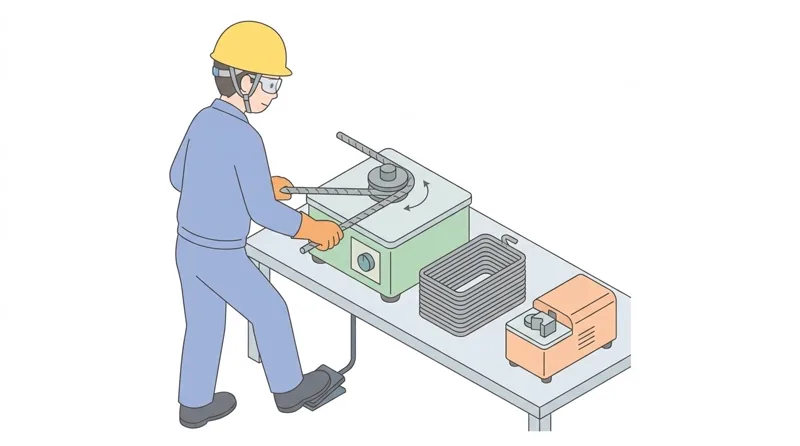
鉄筋の曲げ加工は必ず熱を加えない「常温加工」で行い、一度曲げた鉄筋の「曲げ戻し(曲げ直し)」は亀裂や強度低下を招くため禁止です。フック先端の直線余長は、180度フックで「4d以上」、135度フックで「6d以上」、90度フックで「8d以上」とします。
Bending must always be performed cold ('ambient-temperature bending'), and 're-bending (straightening)' a previously bent bar is prohibited because it causes cracking and strength loss. Straight tail extensions for hooks must be at least '4d' for 180° hooks, '6d' for 135° hooks, and '8d' for 90° hooks.
曲げ内直径は鉄筋ベンダーの中心ローラー(芯金)で調整し、帯筋・あばら筋(D16以下)は「3d以上」、SD345の主筋はD16以下で「3d以上」、D19〜D25で「4d以上」とします。加工寸法の許容差は、帯筋・あばら筋で「±5mm」です。
The inside bend diameter is set by selecting the center mandrel roller (Shingane) on the bender: at least '3d' for hoops/stirrups (D16 or smaller), '3d' for SD345 main bars D16 or smaller, and '4d' for SD345 main bars D19 to D25. The fabrication dimensional tolerance for hoops and stirrups is '±5 mm'.
Key points
- 鉄筋の曲げ加工は「常温」で行い、一度曲げた鉄筋の「曲げ直し」は強度低下・亀裂防止のため行ってはならない
Bend reinforcing bars at 'ambient temperature (cold bending)', and never 're-bend' a bar once bent to prevent micro-cracks and strength loss - フック先端の余長は「180度=4d以上、135度=6d以上、90度=8d以上」とし、曲げ内直径は帯筋・あばら筋(D16以下)で「3d以上」、SD345主筋(D19〜D25)で「4d以上」とする
Hook tail extensions are '180° ≥ 4d, 135° ≥ 6d, 90° ≥ 8d'; minimum inside bend diameter is '≥ 3d' for hoops/stirrups (≤ D16) and '≥ 4d' for SD345 main bars (D19–D25) - 帯筋・あばら筋の外寸は「部材幅−2×かぶり厚さ」であり、加工寸法の許容差は「±5mm」である
Hoop/stirrup outside dimension equals 'member width − 2 × cover thickness', with a fabrication dimensional tolerance of '±5 mm'
| Word | Meaning |
|---|---|
| 配筋施工図・加工帳 | rebar shop drawing and bar bending schedule (Kakōchō) |
| 切断長さ(切り寸) | cutting length (Kirisun) |
| 常温加工(曲げ直し禁止) | cold / ambient-temperature bending (re-bending prohibited) |
| 曲げ内直径・直線余長 | inside bend diameter and straight tail extension (Yochō) |
| 加工寸法の許容差(±5mm) | fabrication dimensional tolerance (±5 mm) |
墨出し・割付け・鉄筋相互のあきとハッカーによる結束
Layout Marking, Pitch Marking, Clear Spacing Between Bars, and Tying with a Hakka Hook
鉄筋を組み立てる前には、まず捨てコンクリートや作業床の上に柱・壁・梁の基準線を出す「墨出し」を行います。さらにスケールで測りながら四隅の主筋等にチョーク(石筆)で帯筋・あばら筋の配置位置を示す「割付け印」を付けます。
Before assembling reinforcing bars, 'layout marking (Sumidashi)' is performed on the blinding concrete or work deck to establish reference lines for columns, walls, and beams. Next, using a tape measure and soapstone chalk, 'pitch marks (Waritsuke)' are drawn on the four corner main bars to indicate hoop or stirrup positions.
並行する鉄筋どうしの間には、コンクリートの粗骨材(砂利・砕石)が詰まらず隅々まで充填されるよう所定の「あき(内法間隔)」を設けます。異形棒鋼の最小あきは「25mm以上」「呼び名の数値の1.5倍以上」「粗骨材最大寸法の1.25倍以上」のうち最大値とします。
A minimum 'clear distance (Aki)' must be maintained between parallel bars so coarse aggregate in the concrete can flow freely without bridging. The minimum clear spacing for deformed bars is the largest of: '25 mm or more', '1.5 times the nominal bar size or more', and '1.25 times the maximum coarse aggregate size or more'.
鉄筋の交差部は、直径0.8mm(#21)または0.9mm(#20)の「なまし鉄線(結束線)」と「ハッカー」を用いて結束します。たるみが出ないよう手前に引きながら締め、ねじった先端はかぶり内に突き出してさび汁の原因にならないよう必ず内側へ倒します。
Bar intersections are tied using 0.8 mm (#21) or 0.9 mm (#20) 'annealed iron wire (tie wire)' and a 'rebar tier hook (Hakka)'. Pull the wire toward yourself while twisting to eliminate slack, and always bend the twisted tail inward so it does not protrude into the concrete cover and cause rust stains.
結束方法には、一般交差部に使う「片だすき結束」「十字結束」、柱主筋や太径の梁主筋がずれないよう結束線を2つ折りにして強固に引き寄せる「二つ折り片だすき結束」や「袋結束」があります。なお帯筋・あばら筋の135度フック位置は1箇所に集中させず交互(千鳥)に配置します。
Tying methods include the 'single diagonal tie (Katadasuki)' and 'figure-eight cross tie (Jūji)' for general intersections, and the 'double-folded diagonal tie (Futatsu-ori katadasuki)' or 'bag tie (Fukuro)' to firmly hold vertical column bars or heavy beam bars. Also, 135° hook positions on hoops and stirrups must be alternated (staggered) at each tier.
Key points
- 組立前に「墨出し」と主筋への「割付け印付け」を行い、帯筋・あばら筋の135度フックは段ごとに交互(千鳥)に配置する
Perform 'layout marking' and 'pitch marking on main bars' before assembly, and alternate (stagger) the 135° hook positions of hoops and stirrups - 鉄筋相互の最小あきは「25mm以上」「1.5d以上」「粗骨材最大寸法×1.25以上」の最大値とし、ジャンカ(充填不良)を防ぐ
Minimum clear spacing between bars is the greatest of '≥ 25 mm', '≥ 1.5d', and '≥ 1.25 × max coarse aggregate size' to prevent honeycombing - 0.8mmまたは0.9mmのなまし鉄線を手前に引きながらハッカーで締め、先端はかぶり内に出ないよう「内側」へ倒す
Tighten 0.8 mm or 0.9 mm annealed tie wire with a Hakka hook while pulling toward yourself, and bend the wire tail 'inward' away from the cover zone
| Word | Meaning |
|---|---|
| 墨出し・割付け | layout marking (Sumidashi) and pitch marking (Waritsuke) |
| 鉄筋相互のあき | clear spacing between reinforcing bars (Aki) |
| なまし鉄線(0.8mm・0.9mm)とハッカー | annealed iron wire (0.8 mm / 0.9 mm) and Hakka tier hook |
| 片だすき結束・二つ折り片だすき結束 | single diagonal tie and double-folded diagonal tie |
鉄筋の定着と重ね継手・溶接金網の施工
Anchorage of Reinforcing Bars, Lap Splices, and Welded Wire Mesh Construction
鉄筋が引張力で抜け出さないよう、つながる他の部材のコンクリート内に所定の長さだけ埋め込むことを「定着」といいます。大梁の主筋は柱内に、小梁の主筋は大梁内に、スラブ筋は梁や壁内に定着させます。
Embedding a reinforcing bar into the concrete of an intersecting member for a specified length so it will not pull out under tension is called 'anchorage (Teichaku)'. Main girder bars are anchored into columns, secondary beam bars into main girders, and slab bars into beams or walls.
小梁の下端筋を大梁に定着させる際は、大梁の下端筋の「上」に乗せて入れます。また柱と梁が交わる「仕口部(接合部)」は地震時に大きな力がかかるため、鉄筋が混み合っていても柱の帯筋を絶対に抜き取ってはなりません。
When anchoring the bottom bars of a secondary beam into a main girder, they must be placed 'on top of' the bottom bars of the main girder. Furthermore, at the 'beam-column joint core (Shikuchibu)', which experiences severe seismic forces, column hoops must never be omitted even when bars are congested.
鉄筋どうしを所定の長さだけ重ねてなまし鉄線で2箇所以上緊結する継手を「重ね継手」といいます。継手は引張応力が小さい場所に設け、隣り合う鉄筋の継手位置が同じ断面に集中しないよう相互にずらす「千鳥配置」とします。
A 'lap splice (Kasane tsugite)' joins two bars by overlapping them for a specified length and tying them tightly with annealed wire at two or more points. Splices should be located where tensile stress is small and 'staggered (Chidori)' so adjacent splices do not concentrate in the same cross-section.
なお、異形棒鋼の先端にフックがあっても「フック部分は重ね継手長さに含めない」規則です。また「D35以上の異形鉄筋」には原則として重ね継手を用いません。土間スラブ等の「溶接金網」の重ね継手は、最外縁の横線間距離を「横線間隔+50mm以上かつ150mm以上」として結束します。
Note that even if a deformed bar has a hook at its end, 'the hook portion is not included in the lap splice length'. Under Standard Specifications, lap splices are not used in principle for large bars 'D35 and larger'. For 'welded wire mesh', lap splices require the distance between outermost cross wires to be at least 'cross-wire spacing + 50 mm' and at least '150 mm'.
Key points
- 梁主筋は柱内に所定長さ「定着」させ、小梁の下端筋は大梁の下端筋の「上」に配筋し、柱梁仕口部の帯筋は絶対に省かない
Anchor beam main bars into columns to the specified length, place secondary beam bottom bars 'on top of' main girder bottom bars, and never omit column hoops in joint cores - 重ね継手は応力の小さい位置で「千鳥配置」とし、先端のフックは重ね継手長さに含めず、なまし鉄線で2箇所以上緊結する
Place lap splices in low-stress zones in a 'staggered arrangement', exclude end hooks from the required lap length, and tie at two or more points - 「D35以上の異形鉄筋」には原則として重ね継手を用いず、溶接金網の重ね継手は「横線間隔+50mm以上かつ150mm以上」重ねて結束する
Do not use lap splices in principle for bars 'D35 and larger', and overlap welded wire mesh by 'at least cross-wire spacing + 50 mm and at least 150 mm'
| Word | Meaning |
|---|---|
| 定着長さ・柱梁仕口部 | anchorage length and beam-column joint core (Shikuchibu) |
| 重ね継手(千鳥配置) | lap splice (staggered arrangement / Chidori) |
| D29以上の重ね継手禁止原則 | rule against lap splicing bars D35 and larger |
| 溶接金網(横線間隔+50mm以上かつ150mm以上) | welded wire mesh (overlap ≥ cross-wire pitch + 50 mm and ≥ 150 mm) |
ガス圧接継手・機械式継手の施工と品質検査
Construction and Quality Inspection of Gas Pressure Welded Splices and Mechanical Splices
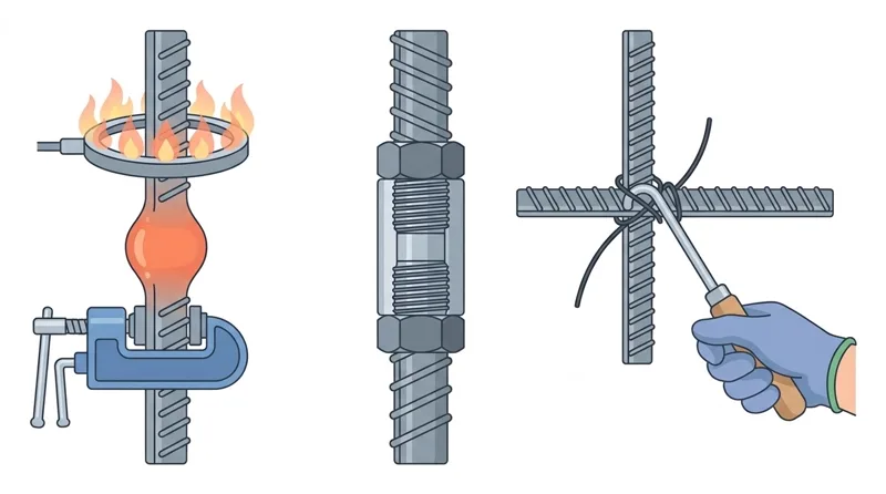
「ガス圧接継手」は、鉄筋の端面どうしを突き合わせ、油圧ポンプと圧接器で軸方向に加圧しながら酸素・アセチレン炎で加熱し、接合面を溶かさずに一体化させる継手です。作業には「手動ガス圧接技量資格(JIS Z 3881)」が必要です。
A 'gas pressure welded splice' butts two bar end faces together and applies axial pressure with a hydraulic clamp while heating the joint with an oxy-acetylene flame to bond the bars integrally in the solid phase. Operators must hold a 'Manual Gas Pressure Welding Qualification (JIS Z 3881)'.
圧接当日(直前)に端面をグラインダーで軸に対して直角かつ平滑に研削し、さび・油・塗料を完全に除去してすき間2〜3mm以下で突き合わせます。径の差が「7mmを超える」異径鉄筋どうしや、雨天・強風時(風除け・雨除けがない場合)は圧接を行いません。
On the day of welding, bar end faces are ground flat and perpendicular to the axis with a grinder to remove all rust, oil, and paint, keeping the gap within 2 to 3 mm when butted. Gas pressure welding is prohibited when nominal bar diameters differ by 'more than 7 mm' or during rain/strong wind without shelter.
圧接後の赤熱部に水をかけて急冷することは厳禁です。良品の基準は、ふくらみの直径が「1.4d以上」、ふくらみの長さが「1.1d以上」、軸の偏心量が「1/5d(0.2d)以下」、ふくらみ頂部のずれが「1/4d以下」であり、全数の外観検査と抜取りの超音波探傷検査を行います。
Quenching a red-hot weld with water is strictly prohibited. Acceptance criteria require a bulge diameter of '1.4d or more', bulge length of '1.1d or more', axial eccentricity of '1/5d (0.2d) or less', and bulge peak offset within '1/4d', verified by 100% visual inspection plus lot-sampled ultrasonic testing.
またカプラー(継手管)でつなぐ「機械式継手(ねじ節鉄筋継手・モルタル充填式継手等)」は天候に左右されにくく太径鉄筋に多用されます。施工前に鉄筋へ挿入長さの「標線(マーキング)」を記し、トルクレンチでのロックナット締付けやグラウト注入後に確認します。
'Mechanical splices' joining bars with couplers (threaded-lug lock-nut couplers or grout-filled sleeves) are less affected by weather and widely used for large bars. Before assembly, a 'reference insertion mark (Hyōsen)' is drawn on the bar and verified after torque-wrench tightening or grouting.
Key points
- ガス圧接は有資格者が行い、当日グラインダーで端面を直角・平滑に研削し、赤熱部の水かけ急冷や径差7mm超の圧接は禁止である
Gas pressure welding must be done by certified technicians after grinding end faces flat and square on the same day; water quenching and welding bars differing by > 7 mm in diameter are prohibited - 圧接部の基準は「ふくらみ直径1.4d以上・長さ1.1d以上・偏心量1/5d以下」であり、全数外観検査とロットごとの超音波探傷検査を行う
Gas pressure weld standards: 'bulge diameter ≥ 1.4d, bulge length ≥ 1.1d, eccentricity ≤ 1/5d', inspected via 100% visual inspection and lot ultrasonic testing - 機械式継手では、カプラーへの挿入不足を防ぐため必ず鉄筋に「挿入長さの標線(マーキング)」を記して施工・確認する
For mechanical splices, always mark the 'insertion length reference line (Hyōsen)' on the bar beforehand to verify full engagement inside the coupler
| Word | Meaning |
|---|---|
| ガス圧接継手(手動ガス圧接技量資格) | gas pressure welded joint (JIS Z 3881 qualification) |
| 圧接端面の研削 | grinding of pressure welding end faces |
| ふくらみ(直径1.4d以上・長さ1.1d以上) | weld bulge (diameter ≥ 1.4d, length ≥ 1.1d) |
| 超音波探傷検査 | ultrasonic flaw detection test |
| 機械式継手(カプラー・標線) | mechanical splice (coupler and reference mark Hyōsen) |
土木構造物の配筋(擁壁・場所打ち杭)と鉄筋の先組み工法
Civil Engineering Reinforcement (Retaining Walls, Cast-in-Place Piles) and Pre-Assembly Method
土木工事で造られる「逆T型擁壁」や「L型擁壁」では、たて壁の背後にある埋戻し土から「土圧」が作用するため、土に接する「背面側(裏側)」に強い引張力が生じます。したがって、主な縦方向の主筋は必ず土に接する背面側に配置します。
In 'inverted-T' and 'L-shaped retaining walls' built in civil engineering works, lateral 'earth pressure' from the backfill acts against the vertical stem wall, producing high tensile force on the 'rear face in contact with the soil'. Therefore, the primary vertical main bars must be placed on the rear soil-contact face.
橋台・橋脚や地下の「ボックスカルバート(箱型暗渠)」では、大口径(D29〜D51など)の鉄筋が多用され、ハンチ部(隅角部)には応力集中に備えてハンチ筋を正確に配置します。
In bridge abutments, piers, and underground 'box culverts', large-diameter reinforcing bars (such as D29 to D51) are widely used, and diagonal 'haunch bars' are accurately placed at the interior corner haunches to resist stress concentration.
軟弱地盤等で支持層まで設ける「場所打ちコンクリート杭」では、主筋の周囲に帯筋(フープ)と補強リングを組んだ円筒状の「鉄筋かご」を製作します。掘削孔の孔壁を傷つけず所定のかぶり厚さを保つため、外周にフラットバーの「わん曲スペーサー(または車輪型スペーサー)」を取り付けます。
For 'cast-in-place concrete piles' reaching down to a bearing stratum, a cylindrical 'rebar cage' is fabricated with main bars, hoops, and stiffening rings. Curved flat-bar 'skid spacers (or wheel-type spacers)' are attached around the outside of the cage to protect the borehole wall and ensure proper concrete cover.
また地上の架台や工場であらかじめ柱・梁の鉄筋を組み立ててからクレーンで所定位置へ吊り込む「先組み工法」は、高所作業を減らして安全性と品質を高められます。吊り上げ時は鉄筋かごが変形しないよう補強材や専用の吊り治具(天秤)を使用します。
In the 'pre-assembly method (Sakigumi kōhō)', column and beam rebar cages are pre-assembled on ground racks or in a plant and hoisted into position by crane, reducing work at height and improving safety and quality. During hoisting, stiffening bars and a dedicated spreader beam (lifting beam) prevent cage deformation.
Key points
- 擁壁(逆T型・L型)のたて壁では、背面土圧による引張力に抵抗するため「土に接する背面側」に主筋を配置する
In retaining wall stems (inverted-T and L-type), place primary vertical main reinforcement on the 'rear face in contact with backfill soil' to resist earth-pressure tension - 場所打ちコンクリート杭の鉄筋かご外周には、孔壁保護とかぶり厚さ確保のため「わん曲スペーサー(車輪型スペーサー)」を取り付ける
Attach 'curved skid spacers (or wheel spacers)' around cast-in-place pile rebar cages to protect the borehole wall and maintain concrete cover - 地上で組んでクレーンで吊り込む「先組み工法」では、吊り上げ時の変形防止のため補強材と専用吊り治具(天秤)を用いる
In the ground 'pre-assembly method (Sakigumi)', use stiffening bars and a dedicated spreader beam (lifting jig) to prevent deformation during crane hoisting
| Word | Meaning |
|---|---|
| 擁壁の背面土圧と引張側主筋 | backfill earth pressure on retaining walls and tension-side main bars |
| ボックスカルバート・ハンチ筋 | box culvert and corner haunch reinforcing bar |
| 場所打ち杭の鉄筋かご・わん曲スペーサー | cast-in-place pile rebar cage and curved skid spacer |
| 先組み工法・吊り治具(天秤) | pre-assembly method (Sakigumi) and lifting spreader beam (Tenbin) |
配筋検査・打設時の相番と鉄筋工事の安全衛生
Rebar Inspection, Concrete Pour Attendance, and Safety and Health in Rebar Work
型枠を閉じる前(コンクリート打設前)には必ず「配筋検査」を行い、鋼種・径・本数・ピッチ・かぶり厚さ・定着や継手の長さ・スペーサーの配置・開口補強筋(四隅の斜め筋等)を確かめます。また下げ振りや水平器で柱・壁の「建入れ(鉛直)」を確認し控え材で固定します。
Before closing formwork (prior to placing concrete), a 'rebar inspection (Haikin kensa)' must be conducted to check steel grades, diameters, bar counts, pitch, concrete cover, anchorage/splice lengths, spacers, and opening reinforcement (diagonal bars at all four corners). Column and wall 'plumbness (Tate-ire)' is checked with a plumb bob or level and braced.
鉄筋表面の「浮きさび」や油はワイヤーブラシで除去し(薄い赤さびはそのまま可)、型枠内の結束線くずを清掃します。スラブ上には「歩み板」を設けて上端筋の沈下を防ぎ、打設中も「相番」が立ち会い、バイブレータを鉄筋に当てないよう注意して乱れを手直しします。
Remove 'loose flaky rust (Ukisabi)', oil, and mortar splash with a wire brush (light adherent red rust is acceptable), and clean wire clippings and wood debris out of the formwork. Lay 'walking boards (Ayumi-ita)' on trestles over slabs to prevent top bars (especially in cantilevered slabs) from sinking, and station a standby rebar worker ('Aiban') during pouring while keeping vibrators off the bars.
安全衛生面では、基礎やスラブからの「差し筋」の先端に必ず「保護キャップ(養生キャップ)」を取り付けて刺し傷災害を防ぎます。高さ2m以上の高所作業では「フルハーネス型墜落制止用器具」を使い、柱の帯筋や壁の横筋を足掛かりにして昇降することは厳禁です。
For safety, always fit 'protective caps' over the protruding ends of 'starter bars (Sashikin)' rising from foundations or slabs to prevent impalement injuries. Use a 'full-body harness' when working at heights of 2 m or more, and strictly prohibit climbing up or down by stepping on column hoops or horizontal wall bars.
つり上げ荷重1t以上のクレーンでの「玉掛け作業」は技能講習修了者が行い、長尺鉄筋は吊り角度60度以内の2点吊りで地切り確認を行い、吊り荷の下には絶対に立ち入りません。また電動機械の「漏電遮断器・アース接続」と点検時の電源遮断、夏場の「水分・塩分補給」による熱中症予防を徹底します。
'Slinging work (Tamagake)' for cranes with a lifting capacity of 1 ton or more must be performed by certified personnel using a balanced two-point hitch with a sling angle of 60° or less, pausing for a lift-off check, and never allowing anyone under a suspended load. Connect electric machines through an 'earth leakage breaker and ground wire', shut off power before maintenance, and replenish water and salt in summer.
Key points
- 打設前に配筋検査・建入れ確認・浮きさび除去・型枠内清掃を行い、スラブ上には「歩み板」を渡し、打設中も「相番」が立ち会って乱れを手直しする
Before concrete placement, complete rebar inspection, plumbness checks, loose-rust removal, and formwork cleaning; lay 'walking boards' on slabs and assign a 'standby rebar worker (Aiban)' during the pour - 差し筋先端には刺傷防止の「保護キャップ」を付け、高さ2m以上ではフルハーネスを使用し、帯筋・横筋を足掛かりにして昇降してはならない
Install 'protective caps' on starter bar ends, wear a full-body harness at heights of 2 m or more, and never climb on column hoops or wall bars - 玉掛けは有資格者が吊り角度60度以内の2点吊りで行い吊り荷の下への立入りを禁じ、電動機械の漏電遮断器・アース接続と熱中症予防を徹底する
Certified riggers must sling long bundles at two points with a sling angle ≤ 60° while prohibiting entry under suspended loads, and ensure earth leakage breakers, grounding, and heatstroke prevention
| Word | Meaning |
|---|---|
| 配筋検査・開口補強筋 | rebar inspection (Haikin kensa) and opening reinforcement |
| 浮きさびの除去・歩み板 | removal of loose flaky rust (Ukisabi) and walking board (Ayumi-ita) |
| 差し筋の保護キャップ | protective cap for starter bars (Hogo cap) |
| 玉掛け(2点吊り・吊り角度60度以内) | slinging work Tamagake (two-point lift, sling angle within 60 degrees) |
| 漏電遮断器とアース(接地) | earth leakage circuit breaker and grounding (earth) |
Rebar Work (Fabrication, Assembly, Pressure Welding, Inspection)
Practice this chapter in the appOfficial references
- 技能トレーニング(建トレ)「鉄筋施工」(国土交通省・公益社団法人全国鉄筋工事業協会) — https://www.mlit.go.jp/tochi_fudousan_kensetsugyo/const/tochi_fudousan_kensetsugyo_const_fr2_000001_00037.html
- 公共建築工事標準仕様書(建築工事編)令和7年版 第5章 鉄筋工事(国土交通省) — https://www.mlit.go.jp/gobuild/gobuild_tk2_000017.html
- 建設分野特定技能1号評価試験 学科・実技試験テキスト 建築・土木「鉄筋施工」(一般社団法人建設技能人材機構 JAC) — https://jac-skill.or.jp/exam/textbook.html
- 鉄筋施工技能検定 試験基準および実技・学科試験問題(厚生労働省・中央職業能力開発協会 JAVADA) — https://www.javada.or.jp/jigyou/gino/giken/