
Power Distribution & Wiring Design
配電理論及び配線設計
Class 2 Electrician 第二種電気工事士 (written exam) · 第二種電気工事士(学科試験) · Written by Tokutei Pass based on the official study texts; not copied verbatim.
低圧配電方式の特徴(単相2線式・単相3線式・三相3線式)
Characteristics of Low-Voltage Distribution Systems (1-Phase 2-Wire, 1-Phase 3-Wire, 3-Phase 3-Wire)
柱上変圧器から一般住宅や店舗へ電気を送る低圧配電方式には、「単相2線式」「単相3線式」「三相3線式」の3種類があります。問題1の問6から問10がこの分野から出題されます。
There are three low-voltage distribution systems used to deliver electricity from pole transformers to residences and shops: "single-phase 2-wire", "single-phase 3-wire", and "three-phase 3-wire". Questions 6 through 10 of Part 1 on the exam come from this chapter.
「単相2線式(100V)」は、非接地側電線(黒色)と接地側電線(白色)の2本で100Vのみを供給する小規模な方式です。線間電圧も対地電圧(地面との間の電圧)も100Vとなります。
The "single-phase 2-wire system (100 V)" is a small-scale method supplying only 100 V using two wires: an ungrounded live wire (black) and a grounded wire (white). Both the line-to-line voltage and the voltage to ground are 100 V.
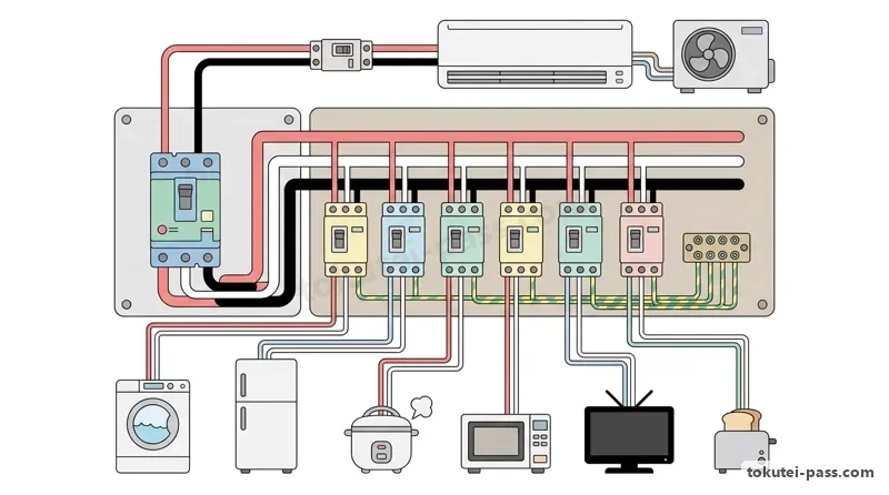
現在の一般住宅で最も広く使われているのが「単相3線式(100V/200V)」です。変圧器の中央から引き出して接地した中性線(白色)と、両外側の電圧線2本(黒色・赤色)の計3本で配線します。
The most widely used system in modern homes is the "single-phase 3-wire system (100 V / 200 V)". It uses three wires in total: a grounded neutral wire (white) tapped from the center of the transformer winding, and two outer voltage wires (black and red).
単相3線式では、外側の線(黒または赤)と中央の中性線(白)の間から照明・コンセント用の「100V」を取り出し、両外側の線同士(黒と赤)の間から大型エアコンやIHクッキングヒーター用の「200V」を同時に取り出せます。
In a single-phase 3-wire system, connecting between either outer wire (black or red) and the center neutral wire (white) provides "100 V" for lighting and general outlets, while connecting between the two outer wires (black and red) simultaneously provides "200 V" for large air conditioners or IH cooktops.
ここで超重要なのが「単相3線式100/200V回路の対地電圧は、200V機器であっても100V(150V以下)である」という点です。一方、工場の電動機に使う「三相3線式200V」は1線を接地するため、対地電圧が200V(150Vを超える)になります。
A crucial point here is that "the voltage to ground in a single-phase 3-wire 100/200 V circuit is 100 V (150 V or less), even for 200 V appliances." Conversely, a "three-phase 3-wire 200 V" system used for factory motors grounds one phase wire, making its voltage to ground 200 V (exceeding 150 V).
Key points
- 単相3線式は外側の電圧線(黒・赤)と中央の中性線(白)で100V、両外側の間で200Vを取り出せる。
Single-phase 3-wire provides 100 V between an outer voltage wire (black/red) and the center neutral wire (white), and 200 V between the two outer wires. - 単相3線式100/200Vは中央の中性線が接地されているため、200V負荷でも対地電圧は「100V」である。
Because the center neutral wire of a single-phase 3-wire 100/200 V system is grounded, the voltage to ground is "100 V" even for 200 V loads. - 三相3線式200V(デルタ結線1線接地)の対地電圧は「200V(150Vを超える)」となる。
A three-phase 3-wire 200 V system (delta with one corner grounded) has a voltage to ground of "200 V (exceeding 150 V)".
| Word | Meaning |
|---|---|
| 単相2線式と単相3線式 | single-phase 2-wire and single-phase 3-wire systems |
| 三相3線式 | three-phase 3-wire system |
| 中性線(白色)と電圧線(黒色・赤色) | neutral wire (white) and voltage wires (black, red) |
| 対地電圧 | voltage to ground |
単相2線式および単相3線式の電圧降下と電力損失の計算
Voltage Drop and Power Loss Calculations in 1-Phase 2-Wire and 1-Phase 3-Wire Systems
問6・問7では、電線そのものが持つわずかな抵抗r(Ω)によって生じる「電圧降下ΔV(V)」と「配電線路の電力損失Pl(W)」の計算が出題されます(負荷の力率cosφ=1とします)。
Questions 6 and 7 test calculations of "voltage drop ΔV (V)" and "line power loss Pl (W)" caused by the small resistance r (Ω) of each distribution wire (assuming load power factor cosφ = 1).
「単相2線式」では、行きの電線と帰りの電線の「合計2本」に同じ電流I(A)が流れます。したがって電線1本の抵抗をr(Ω)とすると、往復2本分の電圧降下は「ΔV=2×r×I(V)」、電力損失は「Pl=2×r×I²(W)」となります。
In a "single-phase 2-wire system", the same current I (A) flows through both the outgoing wire and the return wire (a total of 2 wires). Therefore, if the resistance of one wire is r (Ω), the round-trip voltage drop is "ΔV = 2 × r × I (V)", and the power loss is "Pl = 2 × r × I² (W)".
「単相3線式」において、上段の負荷電流I1と下段の負荷電流I2が等しい「平衡負荷(I1=I2=I)」のときは、中央の中性線に流れる電流が打ち消し合って「0A」になります。
In a "single-phase 3-wire system", when the upper load current I1 and lower load current I2 are equal in a "balanced load (I1 = I2 = I)", the currents in the center neutral wire cancel each other out to become "0 A".
中性線の電流が0Aであれば中性線での電圧降下も0Vになるため、各負荷の電圧降下は外側の電線1本分だけの「ΔV=r×I(V)」で済み、線路全体の電力損失は上下2本分の「Pl=2×r×I²(W)」となります。
When neutral wire current is 0 A, the voltage drop along the neutral wire is also 0 V. Thus, the voltage drop for each load is just that of a single outer wire, "ΔV = r × I (V)", and total line power loss is the sum of the top and bottom outer wires: "Pl = 2 × r × I² (W)".
もし上下の電流が異なる不平衡時(例:上段I1>下段I2)は、中性線に差の電流「IN=I1−I2」が左向き(電源側へ戻る向き)に流れ、電力損失は3本それぞれの損失を足した「Pl=r×I1²+r×IN²+r×I2²」で求めます。
If the upper and lower currents differ (unbalanced, e.g., I1 > I2), the difference current "IN = I1 − I2" flows back toward the source through the neutral wire, and total power loss is the sum across all three wires: "Pl = r × I1² + r × IN² + r × I2²".
Key points
- 単相2線式(往復2本):電圧降下は「ΔV=2rI(V)」、電力損失は「Pl=2rI²(W)」である。
Single-phase 2-wire (2 wires round-trip): Voltage drop is "ΔV = 2rI (V)", and power loss is "Pl = 2rI² (W)". - 単相3線式(上下平衡時I1=I2=I):中性線電流が0Aとなり、1相の電圧降下は「ΔV=rI」、損失は「Pl=2rI²」となる。
Single-phase 3-wire (balanced I1 = I2 = I): Neutral current is 0 A, single-phase voltage drop is "ΔV = rI", and power loss is "Pl = 2rI²". - 単相3線式で片側のスイッチを開いたときは、残った側が単相2線式(往復2本)と同じになり損失は「2rI²」となる。
When one switch is opened in a single-phase 3-wire circuit, the remaining side acts like a single-phase 2-wire circuit (2 wires), so loss is "2rI²". - 【例】単相2線式で 1線の抵抗 r = 0.15Ω、電流 I = 20A のとき → 電圧降下 ΔV = 2 × 0.15 × 20 = 6V、電力損失 Pl = 2 × 0.15 × 20 × 20 = 120W
Example: In a single-phase 2-wire circuit with wire resistance r = 0.15Ω and current I = 20A → Voltage drop ΔV = 2 × 0.15 × 20 = 6V, power loss Pl = 2 × 0.15 × 20 × 20 = 120W - 【例】単相3線式(平衡負荷)で 1線の抵抗 r = 0.2Ω、電流 I = 15A のとき → 中性線電流は 0A、1相の電圧降下 ΔV = 0.2 × 15 = 3V、全損失 Pl = 2 × 0.2 × 15 × 15 = 90W
Example: In a balanced single-phase 3-wire circuit with wire resistance r = 0.2Ω and current I = 15A → Neutral current is 0A, single-phase voltage drop ΔV = 0.2 × 15 = 3V, total loss Pl = 2 × 0.2 × 15 × 15 = 90W
| Word | Meaning |
|---|---|
| 電圧降下(ΔV) | voltage drop (ΔV) |
| 電力損失(Pl) | line power loss (Pl) |
| 平衡負荷 | balanced load |
| 中性線電流 | neutral wire current |
三相3線式の電圧降下・電力損失と単相3線式の中性線断線事故
3-Phase 3-Wire Voltage Drop/Loss and Neutral Wire Disconnection in 1-Phase 3-Wire
「三相3線式」では3本の電線すべてに線電流I(A)が流れ、各線の電流には120度ずつの位相差があります。そのため線間の電圧降下は2倍ではなく√3倍の「ΔV=√3×r×I(V)(√3=1.73)」となります。
In a "three-phase 3-wire system", line current I (A) flows through all three wires with a 120-degree phase shift between each wire. Consequently, the line-to-line voltage drop is multiplied by √3 rather than 2: "ΔV = √3 × r × I (V) (where √3 = 1.73)".
一方、三相3線式の電力損失Pl(W)は、抵抗r(Ω)の電線3本それぞれで「r×I²」の熱損失が発生するため、3本分を単純に合計した「Pl=3×r×I²(W)」で求めます。
Meanwhile, the line power loss Pl (W) in a three-phase 3-wire system is simply the sum of the heat loss "r × I²" generated in each of the three wires of resistance r (Ω), giving "Pl = 3 × r × I² (W)".
また問7で頻出なのが、単相3線式100/200V回路で中央の「中性線が断線(切れる)」したときの異常電圧計算です。中性線が切れると、上段の負荷抵抗R1と下段の負荷抵抗R2が「外側の200V電源に直列接続」された状態になります。
Another frequent topic in Question 7 is calculating abnormal voltage when the center "neutral wire breaks (disconnects)" in a single-phase 3-wire 100/200 V circuit. If the neutral wire breaks, the upper load resistance R1 and lower load resistance R2 become "connected in series across the outer 200 V source".
その結果、200Vの電圧が抵抗値の比で分圧され、上段R1にかかる電圧は「V1=200×R1÷(R1+R2)(V)」となります。たとえばR1=100Ω・R2=50Ωなら、R1には「200×100÷150=約133V」もの過電圧がかかり機器が焼損します。
As a result, the 200 V voltage divides in proportion to resistance, applying "V1 = 200 × R1 ÷ (R1 + R2) (V)" across upper load R1. For example, if R1 = 100 Ω and R2 = 50 Ω, an overvoltage of "200 × 100 ÷ 150 ≈ 133 V" is applied to R1, burning out the appliance.
このように中性線が切れると抵抗の大きい(消費電力の小さい)側の100V機器に100Vを超える高電圧がかかって危険なため、多線式電路の中性線には「ヒューズや単極スイッチを絶対に設けてはならない」と法律で定められています。
Because a broken neutral wire subjects 100 V appliances on the higher-resistance (lower-power) side to dangerous overvoltage above 100 V, electrical regulations strictly stipulate that "fuses or single-pole switches must never be installed in the neutral wire" of a multi-wire circuit.
Key points
- 三相3線式の電圧降下は「ΔV=√3×r×I(V)」、電力損失は3本分の「Pl=3×r×I²(W)」である。
In a three-phase 3-wire system, voltage drop is "ΔV = √3 × r × I (V)" and power loss across all 3 wires is "Pl = 3 × r × I² (W)". - 単相3線式の中性線が断線すると、上下の負荷R1・R2に200Vが直列にかかり「V1=200×R1÷(R1+R2)」に分圧される。
If the neutral wire breaks in a single-phase 3-wire circuit, loads R1 and R2 are in series across 200 V, dividing voltage as "V1 = 200 × R1 ÷ (R1 + R2)". - 中性線断線による過電圧焼損を防ぐため、中性線にヒューズ(過電流遮断器)を入れることは厳禁である。
To prevent overvoltage burnout from neutral disconnection, installing a fuse (overcurrent breaker) on the neutral wire is strictly prohibited. - 【例】三相3線式で 1線の抵抗 r = 0.1Ω、線電流 I = 20A のとき → 電圧降下 ΔV = 1.73 × 0.1 × 20 = 3.46V、電力損失 Pl = 3 × 0.1 × 20 × 20 = 120W
Example: In a three-phase 3-wire system with wire resistance r = 0.1Ω and line current I = 20A → Voltage drop ΔV = 1.73 × 0.1 × 20 = 3.46V, power loss Pl = 3 × 0.1 × 20 × 20 = 120W - 【例】単相3線式(線間 200V)で上段負荷 R1 = 60Ω、下段負荷 R2 = 40Ω のとき中性線が断線 → R1にかかる電圧 V1 = 200 × 60 ÷(60 + 40)= 120V
Example: If the neutral breaks in a single-phase 3-wire circuit (200V line-to-line) with upper load R1 = 60Ω and lower load R2 = 40Ω → Voltage across R1 is V1 = 200 × 60 ÷ (60 + 40) = 120V
| Word | Meaning |
|---|---|
| 三相3線式の電圧降下(√3rI) | three-phase 3-wire voltage drop (√3rI) |
| 中性線断線 | neutral wire disconnection (break) |
| 過電圧 | overvoltage |
| 多線式電路の中性線 | neutral wire of a multi-wire circuit |
絶縁電線の許容電流(単線とより線)の基準値
Standard Allowable Current of Insulated Wires (Solid Wires and Stranded Wires)
電線に電流が流れるとジュール熱で温度が上がります。絶縁被覆が劣化しない最高許容温度(ビニル絶縁電線IVは60℃)を超えない範囲で流せる最大の電流を「許容電流(単位:A)」といいます。
When current flows through a wire, Joule heat raises its temperature. The maximum current that can flow without exceeding the maximum allowable temperature of the insulation (60°C for vinyl-insulated IV wire) is called the "allowable current (ampacity, unit: A)".
問8を解くためには、600Vビニル絶縁電線(IV)をがいし引きなどで露出配線したときの「基本許容電流」の数値を暗記しておく必要があります。まず1本の銅線でできた「単線(直径mmで表す)」の4サイズを覚えましょう。
To solve Question 8, you must memorize the "base allowable current" values for 600 V vinyl-insulated wire (IV) in open air. First, memorize the four standard sizes of "solid wire (single copper conductor, specified by diameter in mm)".
単線(直径)の許容電流は、「直径1.6mm=27A」「直径2.0mm=35A」「直径2.6mm=48A」「直径3.2mm=62A」です。特に屋内配線の主役である「1.6mm=27A」と「2.0mm=35A」は毎期のように登場します。
The allowable currents for solid wires (by diameter) are: "1.6 mm diameter = 27 A", "2.0 mm diameter = 35 A", "2.6 mm diameter = 48 A", and "3.2 mm diameter = 62 A". In particular, "1.6 mm = 27 A" and "2.0 mm = 35 A" appear on almost every exam.
次に、細い銅線を複数本より合わせた「より線(公称断面積mm²で表す)」の許容電流は、「断面積2.0mm²=27A」「3.5mm²=37A」「5.5mm²=49A」「8.0mm²=61A」「14mm²=88A」です。
Next, the allowable currents for "stranded wires (multiple thin copper wires twisted together, specified by nominal cross-sectional area in mm²)" are: "2.0 mm² area = 27 A", "3.5 mm² = 37 A", "5.5 mm² = 49 A", "8.0 mm² = 61 A", and "14 mm² = 88 A".
ここで最大のひっかけは「直径2.0mm(単線)は35A」であるのに対し、「断面積2.0mm²(より線)は27A(単線1.6mmと同じ)」という点です。問題文の単位が「mm(直径)」か「mm²(断面積)」かを必ず指差し確認してください。
The biggest exam trap here is that "2.0 mm diameter (solid wire) is 35 A", whereas "2.0 mm² cross-sectional area (stranded wire) is 27 A (the same as 1.6 mm solid wire)." Always double-check whether the unit in the question is "mm (diameter)" or "mm² (area)".
Key points
- 単線(直径mm)の許容電流:1.6mm=27A、2.0mm=35A、2.6mm=48A、3.2mm=62A。
Allowable current of solid wires (diameter mm): 1.6 mm = 27 A, 2.0 mm = 35 A, 2.6 mm = 48 A, 3.2 mm = 62 A. - より線(断面積mm²)の許容電流:2.0mm²=27A、3.5mm²=37A、5.5mm²=49A、8.0mm²=61A。
Allowable current of stranded wires (area mm²): 2.0 mm² = 27 A, 3.5 mm² = 37 A, 5.5 mm² = 49 A, 8.0 mm² = 61 A. - 「直径2.0mm(35A)」と「断面積2.0mm²(27A)」の混同が試験で最も多いひっかけである。
Confusing "2.0 mm diameter (35 A)" with "2.0 mm² cross-sectional area (27 A)" is the most common trap on the exam.
| Word | Meaning |
|---|---|
| 許容電流 | allowable current (ampacity) |
| 単線(直径mm) | solid wire (diameter in mm) |
| より線(公称断面積mm²) | stranded wire (nominal cross-sectional area in mm²) |
| 600Vビニル絶縁電線(IV) | 600 V vinyl-insulated wire (IV) |
電線管内に収める電線の電流減少係数と許容電流の計算
Current Reduction Factor for Wires in Conduit and Allowable Current Calculation
複数の絶縁電線を電線管(金属管や合成樹脂管)の中に一緒に収めると、熱がこもって逃げにくくなります。そのため、前項の基本許容電流に「電流減少係数(1未満の数値)」を掛けて許容電流を減らさなければなりません。
When multiple insulated wires are bundled inside a conduit (metal or synthetic resin pipe), heat is trapped and dissipates poorly. Therefore, you must multiply the base allowable current from the previous section by a "current reduction factor (a number less than 1)".
同一電線管内に収める電線本数(接地線や中性線を除く場合もあるが、試験では問題文に本数と係数が与えられることが多い)に応じた電流減少係数は、「3本以下=0.70」「4本=0.63」「5〜6本=0.56」「7〜15本=0.49」です。
The current reduction factors according to the number of wires placed inside the same conduit (usually given in the exam question) are: "3 wires or fewer = 0.70", "4 wires = 0.63", "5 to 6 wires = 0.56", and "7 to 15 wires = 0.49".
管内の許容電流の計算式は「電線1本あたりの許容電流=基本許容電流×電流減少係数」です。問題文に減少係数が書かれていても、基本許容電流(27A・35A・48A・49Aなど)は書かれていないため暗記が必須です。
The formula for allowable current inside a conduit is: "Allowable current per wire = Base allowable current × Current reduction factor". Even when the reduction factor is stated in the problem, the base allowable current (27 A, 35 A, 48 A, 49 A, etc.) is never given and must be memorized.
たとえば「電線管にIV電線の単線1.6mmを3本収めたとき(電流減少係数0.70)」の許容電流は、「27A×0.70=18.9A(四捨五入または選択肢により19A)」となります。4本(0.63)なら「27A×0.63=17.01A(17A)」です。
For example, when "3 solid IV wires of 1.6 mm are placed in a conduit (reduction factor 0.70)", the allowable current is "27 A × 0.70 = 18.9 A (19 A in answer choices)". For 4 wires (0.63), it is "27 A × 0.63 = 17.01 A (17 A)".
同様に「単線2.0mm(35A)を3本(0.70)」なら「35A×0.70=24.5A(24A)」、「より線5.5mm²(49A)を4本(0.63)」なら「49A×0.63=30.87A(30A)」となります。よく出る掛け算の結果もなじんでおくと確実です。
Similarly, "3 solid 2.0 mm wires (35 A) in a conduit (0.70)" gives "35 A × 0.70 = 24.5 A (24 A)", and "4 stranded 5.5 mm² wires (49 A) in a conduit (0.63)" gives "49 A × 0.63 = 30.87 A (30 A)". Being familiar with these common products ensures fast, accurate answers.
Key points
- 電線管内の許容電流は「基本許容電流×電流減少係数」で求める。
Allowable current inside a conduit is calculated as "Base allowable current × Current reduction factor". - 電流減少係数の基準値:3本以下=0.70、4本=0.63、5〜6本=0.56(7の段:70・63・56と覚える)。
Standard current reduction factors: ≤ 3 wires = 0.70, 4 wires = 0.63, 5–6 wires = 0.56 (memorize as multiples of 7: 70, 63, 56). - 頻出計算例:1.6mm×3本=27×0.70=約19A/2.0mm×3本=35×0.70=約24A/1.6mm×4本=27×0.63=約17A。
Frequent calculations: 1.6 mm × 3 wires = 27 × 0.70 ≈ 19 A / 2.0 mm × 3 wires = 35 × 0.70 ≈ 24 A / 1.6 mm × 4 wires = 27 × 0.63 ≈ 17 A. - 【例】直径 2.0mm(基本許容電流 35A)を電線管に 4本(減少係数 0.63)収める → 35 × 0.63 = 22.05A → 22A(5〜6本で係数 0.56 なら 35 × 0.56 = 19.6A → 19A)
Example: Placing four 2.0mm wires (base allowable current 35A, reduction factor 0.63) in a conduit → Allowable current = 35 × 0.63 = 22.05A → 22A (for 5–6 wires with factor 0.56, 35 × 0.56 = 19.6A → 19A)
| Word | Meaning |
|---|---|
| 電流減少係数 | current reduction factor |
| 同一電線管内 | inside the same conduit |
| 放熱 | heat dissipation |
| 最高許容温度 | maximum allowable temperature |
低圧屋内幹線の太さ(IW)と過電流遮断器の定格電流(IB)・分岐距離
Low-Voltage Indoor Feeder Size (IW), Breaker Rating (IB) and Tap Distance Rules
引込口から分電盤や制御盤へ電気を送る太い主配線を「幹線」といいます。問9では、電動機(モーター)の定格電流の合計IMと、電熱器・照明の定格電流の合計IHから、幹線の許容電流IWと遮断器定格IBを求めます。
The main heavy wiring that carries power from the service entrance to distribution boards or control panels is called a "feeder (trunk line)". Question 9 asks you to find the feeder allowable current IW and feeder breaker rating IB from the total motor rated current IM and total heater/lighting current IH.
まず幹線電線の許容電流IWの最小値です。電動機が少なく「IM≤IH(または電動機なし)」のときは、そのまま足した「IW≥IM+IH」で足ります。一方、「IM>IH」のときは始動電流を見込み、IM≤50Aなら「IW≥1.25×IM+IH」(IM>50Aなら「IW≥1.1×IM+IH」)が必要です。
First is the minimum allowable current IW of the feeder wires. When motor load is small, "IM ≤ IH (or no motors)", simply add them: "IW ≥ IM + IH". Conversely, when "IM > IH", you must account for starting current: if IM ≤ 50 A, then "IW ≥ 1.25 × IM + IH" (if IM > 50 A, "IW ≥ 1.1 × IM + IH").
次に幹線を守る過電流遮断器の定格電流IBの最大値です。電動機がないときは「IB≤IW」ですが、電動機があるときは始動電流で切れないよう「IB≤3×IM+IH」かつ「IB≤2.5×IW」の「両方の条件を満たす小さい方の値」を上限とします。
Next is the maximum rated current IB of the overcurrent breaker protecting the feeder. With no motors, "IB ≤ IW"; when motors are present, to prevent nuisance tripping during startup, the upper limit is the "smaller value satisfying both IB ≤ 3 × IM + IH and IB ≤ 2.5 × IW".
また幹線から細い電線(許容電流Iw)を分岐する場合、原則として「分岐点から3m以下」の場所に過電流遮断器を設けなければなりません。
Furthermore, when tapping a smaller branch wire (allowable current Iw) from a feeder, as a general rule an overcurrent breaker must be installed "within 3 m from the tap point".
ただし例外として、分岐電線の許容電流Iwが幹線遮断器定格IBの「35%以上(Iw≥0.35×IB)」あれば「8m以下」まで延ばせ、さらに「55%以上(Iw≥0.55×IB)」あれば「長さの制限なし(何mでも遮断器省略可)」となります。
As exceptions, if the branch wire's allowable current Iw is "at least 35% (Iw ≥ 0.35 × IB)" of the feeder breaker rating IB, the distance may extend to "8 m or less"; if it is "at least 55% (Iw ≥ 0.55 × IB)", there is "no length limit (a breaker may be omitted at any distance)".
Key points
- 幹線電線の許容電流IW:IM≤IHなら「IW≥IM+IH」、IM>IH(かつIM≤50A)なら「IW≥1.25×IM+IH」。
Feeder wire allowable current IW: If IM ≤ IH then "IW ≥ IM + IH"; if IM > IH (and IM ≤ 50 A) then "IW ≥ 1.25 × IM + IH". - 幹線遮断器の定格電流IB(電動機あり):「3×IM+IH」と「2.5×IW」のうち小さい方の値以下とする。
Feeder breaker rating IB (with motors): Must not exceed the smaller of "3 × IM + IH" and "2.5 × IW". - 幹線分岐点から遮断器までの距離:原則3m以下、Iw≥0.35IBなら8m以下、Iw≥0.55IBなら制限なし。
Distance from feeder tap point to breaker: Principle ≤ 3 m; ≤ 8 m if Iw ≥ 0.35 IB; unlimited if Iw ≥ 0.55 IB. - 【例】電動機合計 IM = 20A、電熱器合計 IH = 10A(IM > IH)の幹線 → 必要許容電流 IW = 1.25 × 20 + 10 = 35A以上、IW = 35A の電線なら遮断器上限 IB = 3 × 20 + 10 = 70A(2.5 × 35 = 87.5A より小さい値)
Example: A feeder with total motor current IM = 20A and heater current IH = 10A (IM > IH) → Required allowable current IW = 1.25 × 20 + 10 = 35A or more; using a wire with IW = 35A gives max breaker rating IB = 3 × 20 + 10 = 70A (smaller than 2.5 × 35 = 87.5A) - 【例】幹線遮断器の定格電流 IB = 60A のとき → 分岐距離 8m以下にする分岐線許容電流 Iw = 0.35 × 60 = 21A以上、距離制限なしは Iw = 0.55 × 60 = 33A以上
Example: When feeder breaker rating IB = 60A → Branch wire allowable current for up to 8m is Iw = 0.35 × 60 = 21A or more; for unlimited distance, Iw = 0.55 × 60 = 33A or more
| Word | Meaning |
|---|---|
| 低圧屋内幹線 | low-voltage indoor feeder (trunk line) |
| 過電流遮断器 | overcurrent circuit breaker |
| 始動電流 | starting current |
| 分岐点からの距離制限(3m・8m) | tap distance limits (3 m, 8 m) |
分岐回路の設計(遮断器の定格・電線の太さ・コンセントの組合せ)
Branch Circuit Design (Combinations of Breaker Rating, Wire Size and Receptacles)
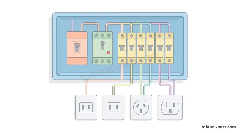
問10では、分電盤の分岐遮断器からコンセントへ至る「分岐回路」について、電気設備技術基準の解釈第149条に定められた「遮断器の定格・電線の太さ・コンセント定格電流の正しい組合せ」が必ず出題されます。
Question 10 always tests "branch circuits" running from branch breakers in the distribution board to receptacles, asking for the "correct (or incorrect) combination of breaker rating, wire thickness, and receptacle rated current" under Article 149 of the Interpretation of Technical Standards.
大原則として「コンセントの定格電流は、分岐回路の定格電流より大きいものを使ってはならず、同じか1段階だけ小さいものを使う」というルールがあります(15A回路は15Aコンセントのみ)。
The overarching rule is that "the rated current of a receptacle must never exceed the branch circuit rating; use a receptacle with the same rating or one step smaller" (a 15 A branch circuit allows only 15 A receptacles).
①「15A分岐回路」および「20A配線用遮断器分岐回路」では、電線は「直径1.6mm以上」、コンセントは「15A(20A回路は15Aまたは20A)」が使えます。②ヒューズを使う通常の「20A分岐回路」は、電線「直径2.0mm以上」、コンセント「20Aのみ」です。
① For a "15 A branch circuit" and a "20 A molded-case circuit breaker (MCCB) branch circuit": wires must be "1.6 mm diameter or larger", and receptacles can be "15 A (or 15 A / 20 A for the 20 A MCCB circuit)". ② For a general "20 A branch circuit" using fuses: wires must be "2.0 mm diameter or larger" and receptacles "20 A only".
③「30A分岐回路」では、電線は「直径2.6mm以上(または断面積5.5mm²以上)」、コンセントは「20Aまたは30A」です。ここに直径2.0mmの電線や15Aコンセントを組み合わせる誤りの選択肢が非常によく出ます。
③ For a "30 A branch circuit": wires must be "2.6 mm diameter or larger (or 5.5 mm² cross-section or larger)", and receptacles must be "20 A or 30 A". Wrong choices pairing a 30 A circuit with 2.0 mm wire or a 15 A receptacle are extremely common exam traps.
④「40A分岐回路」は電線「8.0mm²以上」・コンセント「30Aまたは40A」、⑤「50A分岐回路」は電線「14mm²以上」・コンセント「40Aまたは50A」となります。なお定格15Aや20Aの分岐回路につなげるコンセントの個数に法律上の上限はありません。
④ A "40 A branch circuit" requires "8.0 mm² or larger" wire and "30 A or 40 A" receptacles; ⑤ a "50 A branch circuit" requires "14 mm² or larger" wire and "40 A or 50 A" receptacles. Note that regulations place no upper limit on the number of receptacles connected to a 15 A or 20 A branch circuit.
Key points
- 15A回路:電線1.6mm以上・コンセント15Aのみ/20A配線用遮断器回路:電線1.6mm以上・コンセント15Aまたは20A。
15 A circuit: wire ≥ 1.6 mm, 15 A outlet only / 20 A MCCB circuit: wire ≥ 1.6 mm, 15 A or 20 A outlets allowed. - 30A分岐回路:電線「直径2.6mm以上または断面積5.5mm²以上」・コンセント「20Aまたは30A」(15Aコンセントや2.0mm電線は不可)。
30 A branch circuit: wire "≥ 2.6 mm diameter or ≥ 5.5 mm² area", outlets "20 A or 30 A" (15 A outlets and 2.0 mm wire are prohibited). - 40A分岐回路:電線「8mm²以上」・コンセント「30Aまたは40A」/50A分岐回路:電線「14mm²以上」・コンセント「40Aまたは50A」。
40 A branch circuit: wire "≥ 8 mm²", outlets "30 A or 40 A" / 50 A branch circuit: wire "≥ 14 mm²", outlets "40 A or 50 A".
| Word | Meaning |
|---|---|
| 分岐回路 | branch circuit |
| 20A配線用遮断器分岐回路 | 20 A molded-case circuit breaker branch circuit |
| コンセントの定格電流 | rated current of a receptacle |
| 電技解釈第149条 | Article 149 of the Interpretation of Technical Standards |
試験によく出るポイントと覚え方
Frequently Tested Points & Memory Aids
問6・問7の電圧降下と電力損失は、電線の本数で整理します。「単相2線式=ΔVは2rI・損失は2rI²」「単相3線式平衡時=中性線0AだからΔVは1本分のrI・損失は上下2本分の2rI²」「三相3線式=ΔVは√3rI・損失は3本分の3rI²」です。
For Questions 6 and 7 on voltage drop and power loss, organize by the number of active wires: "1-phase 2-wire = ΔV is 2rI, loss is 2rI²"; "balanced 1-phase 3-wire = neutral is 0 A so ΔV is 1 wire rI, loss is 2 outer wires 2rI²"; "3-phase 3-wire = ΔV is √3rI, loss is 3 wires 3rI²".
問8の許容電流は、単線の「1.6mm=27A、2.0mm=35A、2.6mm=48A(語呂:イロ・フナ、ニ・サンゴ、フロ・ヨンパチ)」と、減少係数の7の段「3本0.70、4本0.63、5〜6本0.56」を掛けるだけです。直径2.0mm(35A)と断面積2.0mm²(27A)の違いに要注意です。
For Question 8 on allowable current, memorize solid wires "1.6 mm = 27 A, 2.0 mm = 35 A, 2.6 mm = 48 A" and multiply by the 7-times-table reduction factors: "≤ 3 wires = 0.70, 4 wires = 0.63, 5–6 wires = 0.56". Watch out for 2.0 mm diameter (35 A) versus 2.0 mm² area (27 A).
問9の幹線分岐距離は「原則3m、35%以上で8m(語呂:サンゴで8m)、55%以上で無制限(語呂:ゴーゴー無制限)」。問10の分岐回路は「30A回路に2.0mm電線や15Aコンセントは使えない(2.6mmまたは5.5mm²以上・コンセント20A/30A)」が最頻出ポイントです。
For Question 9 feeder tap distance: remember "Principle 3 m – 35% gives 8 m – 55% gives unlimited". For Question 10 branch circuits: the #1 trap is "a 30 A circuit cannot use 2.0 mm wire or 15 A outlets (requires ≥ 2.6 mm or 5.5 mm² wire and 20 A/30 A outlets)".
Key points
- 電圧降下と損失:単相2線(ΔV=2rI、Pl=2rI²)/単相3線平衡(ΔV=rI、Pl=2rI²)/三相3線(ΔV=√3rI、Pl=3rI²)。
Voltage Drop & Loss: 1-phase 2-wire (ΔV = 2rI, Pl = 2rI²) / Balanced 1-phase 3-wire (ΔV = rI, Pl = 2rI²) / 3-phase 3-wire (ΔV = √3rI, Pl = 3rI²). - 単線許容電流:1.6mm=27A・2.0mm=35A・2.6mm=48A / より線:2.0mm²=27A・3.5mm²=37A・5.5mm²=49A・8mm²=61A。
Solid wire ampacity: 1.6 mm = 27 A, 2.0 mm = 35 A, 2.6 mm = 48 A / Stranded wire: 2.0 mm² = 27 A, 3.5 mm² = 37 A, 5.5 mm² = 49 A, 8 mm² = 61 A. - 管内電流減少係数:3本以下=0.70、4本=0.63、5〜6本=0.56(基本許容電流に掛ける)。
Conduit reduction factors: ≤ 3 wires = 0.70, 4 wires = 0.63, 5–6 wires = 0.56 (multiply by base allowable current). - 幹線計算:IM>IHなら「IW≥1.25IM+IH」、遮断器「IB≤3IM+IHかつ2.5IW」/分岐距離:3m・35%で8m・55%で制限なし。
Feeder design: If IM > IH then "IW ≥ 1.25 IM + IH", breaker "IB ≤ 3 IM + IH and ≤ 2.5 IW" / Tap distance: 3 m, 8 m at ≥ 35%, unlimited at ≥ 55%. - 分岐回路表:20A配線用遮断器は1.6mm可・15A/20Aコンセント可/30A回路は2.6mm(5.5mm²)以上・20A/30Aコンセントのみ。
Branch circuit table: 20 A MCCB allows 1.6 mm wire & 15 A/20 A outlets / 30 A circuit requires ≥ 2.6 mm (5.5 mm²) wire & 20 A/30 A outlets only.
| Word | Meaning |
|---|---|
| 単相3線式平衡負荷 | balanced load in 1-phase 3-wire system |
| 基本許容電流(27A・35A・48A) | base allowable current (27 A, 35 A, 48 A) |
| 電流減少係数(0.70・0.63・0.56) | current reduction factor (0.70, 0.63, 0.56) |
| 幹線分岐距離(3m・8m・制限なし) | feeder tap distance (3 m, 8 m, unlimited) |
Power Distribution & Wiring Design
Practice this chapter in the appOfficial references
- 経済産業省「電気設備に関する技術基準を定める省令」「電気設備の技術基準の解釈」 — https://www.meti.go.jp/policy/safety_security/industrial_safety/sangyo/electric/
- 一般財団法人 電気技術者試験センター「第二種電気工事士試験 学科試験(配電理論及び配線設計)」 — https://www.shiken.or.jp/