
Electrical Equipment, Wiring Devices, Materials & Tools
電気機器・配線器具並びに電気工事用の材料及び工具
Class 2 Electrician 第二種電気工事士 (written exam) · 第二種電気工事士(学科試験) · Written by Tokutei Pass based on the official study texts; not copied verbatim.
絶縁電線・ケーブル・コードの種類と最高許容温度
Types of Insulated Wires, Cables and Cords, and Maximum Allowable Temperatures
問題1の問11から問18までの8問(16点分)は、材料・配線器具・工具・電気機器および写真鑑別が出題される最重要分野です。まず電線とケーブルの記号および「最高許容温度」を押さえましょう。
The eight questions from Question 11 to Question 18 (worth 16 points) in Part 1 form a vital section covering materials, wiring devices, tools, electrical machines, and photo identification. First, master the letter codes and "maximum allowable temperatures" of wires and cables.
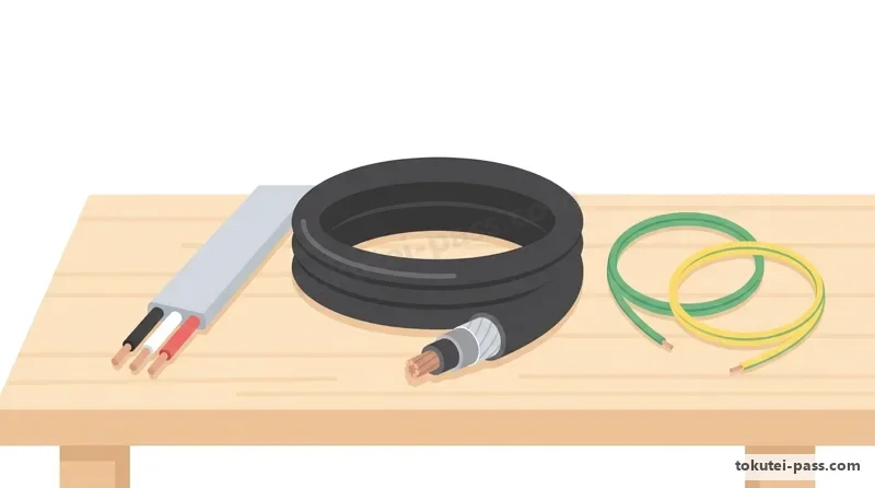
電線管内などに通す「絶縁電線」では、一般の「600Vビニル絶縁電線(IV)」の最高許容温度が「60℃」であるのに対し、耐熱性を高めた「600V二種ビニル絶縁電線(HIV)」と「600V耐燃性ポリエチレン絶縁電線(EM-IE)」は「75℃」です。
Among "insulated wires" pulled through conduits, standard "600 V vinyl-insulated wire (IV)" has a maximum allowable temperature of "60°C", whereas heat-resistant "600 V type-2 vinyl-insulated wire (HIV)" and "600 V flame-retardant polyethylene-insulated wire (EM-IE)" are rated at "75°C".
また屋外の架空配線には「屋外用ビニル絶縁電線(OW)」、電柱から建物への引込線には「引込用ビニル絶縁電線(DV)」が使われます。なおOW電線は絶縁被覆が薄いため、金属管内などの屋内配線には絶対に使えません。
For outdoor overhead wiring, "outdoor weatherproof vinyl-insulated wire (OW)" is used, and for service drops from utility poles to buildings, "service-drop vinyl-insulated wire (DV)" is used. Because OW wire has thin insulation, it must never be used for indoor wiring such as inside metal conduits.
絶縁電線の上をさらに外装(シース)で覆った「ケーブル」では、住宅配線の主役である平形の「VVF」と丸形の「VVR」(ともにビニル絶縁ビニルシースケーブル)が「60℃」、燃やしても有毒なハロゲンガスが出ないエコケーブル「EM-EEF」が「75℃」です。
Among "cables" (insulated cores covered with an outer protective sheath), flat "VVF" and round "VVR" cables (vinyl-insulated vinyl-sheathed cables) used in residential wiring are rated at "60°C", while eco-friendly "EM-EEF" cable—which emits no toxic halogen gas when burned—is rated at "75°C".
そして幹線の地中埋設などに使う「600V架橋ポリエチレン絶縁ビニルシースケーブル(CV)」の最高許容温度は最も高い「90℃」です。なお家電製品につなぐ「コード」は造営材(壁や柱)に直接固定して屋内配線として使うことは禁じられています。
Finally, "600 V cross-linked polyethylene-insulated vinyl-sheathed cable (CV)", widely used for feeders and underground burial, has the highest maximum allowable temperature at "90°C". Note that flexible "cords" for appliances must never be fastened directly to building surfaces as permanent indoor wiring.
Key points
- 最高許容温度の暗記:IV・VVF・VVR=「60℃」、HIV・EM-IE・EM-EEF=「75℃」、CVケーブル=「90℃」。
Memorize maximum allowable temperatures: IV, VVF, VVR = "60°C"; HIV, EM-IE, EM-EEF = "75°C"; CV cable = "90°C". - EM-IEおよびEM-EEFは火災時に有害なハロゲンガスや黒煙を発生しない環境配慮型(エコ)電線・ケーブルである。
EM-IE and EM-EEF are eco-friendly wires/cables that do not emit toxic halogen gases or heavy black smoke during a fire. - 屋外用ビニル絶縁電線(OW)やビニルコードは、屋内の電線管内や壁面固定配線には使用できない。
Outdoor vinyl wire (OW) and flexible appliance cords cannot be used inside indoor conduits or fastened directly to walls as indoor wiring.
| Word | Meaning |
|---|---|
| 600V二種ビニル絶縁電線(HIV:75℃) | 600 V type-2 vinyl-insulated wire (HIV: 75°C) |
| 600V架橋ポリエチレン絶縁ビニルシースケーブル(CV:90℃) | 600 V cross-linked polyethylene cable (CV: 90°C) |
| EM-EEFケーブル(エコケーブル:75℃) | EM-EEF cable (eco-cable: 75°C) |
| 屋外用ビニル絶縁電線(OW)と引込用(DV) | outdoor weatherproof wire (OW) and service-drop wire (DV) |
電線管(合成樹脂管・金属管・可とう電線管)の種類と特徴
Types and Features of Conduits (Synthetic Resin, Metal and Flexible Conduits)
絶縁電線を通して衝撃や水気から保護する電線管は、「合成樹脂管」と「金属管」に大別されます。図記号のアルファベットと実物の用途をセットで覚えることが重要です。
Conduits through which insulated wires are drawn to protect them from mechanical impact and moisture are broadly divided into "synthetic resin conduits" and "metal conduits". It is important to memorize both the drawing symbol letters and the practical application of each type.
合成樹脂管のうち、灰白色の硬い直管が「硬質塩化ビニル電線管(記号:VE)」です。一方、自由に曲げられる蛇腹状(波形)の管には、自己消火性(難燃性)のある「合成樹脂製可とう電線管(PF管:クリーム色や黒色)」と、難燃性のないオレンジ色の「CD管」があります。
Among synthetic resin conduits, the rigid greyish-white straight pipe is "rigid polyvinyl chloride conduit (symbol: VE)". Meanwhile, flexible corrugated conduits include self-extinguishing (flame-retardant) "synthetic resin pliable conduit (PF pipe: cream or black)" and non-flame-retardant orange "CD pipe".
PF管は燃えにくいため隠ぺい場所や露出場所に広く使えますが、オレンジ色の「CD管(複合可とう管)」は燃えやすいため、原則として「コンクリートに直接埋め込む場所(コンクリート埋設)」にしか使用できません。
Because PF pipe is flame-retardant, it can be used widely in concealed or exposed locations. However, orange "CD pipe (combined ductile pipe)" burns easily and, in principle, may only be used where "embedded directly in concrete".
また地中埋設配線には、外圧に強い波形の「波付硬質合成樹脂管(記号:FEP)」が使われます。金属管には、管端にねじを切って接続する「厚鋼電線管(G:偶数番号G16・G22等)」と「薄鋼電線管(C:奇数番号C19・C25等)」があります。
For underground buried wiring, corrugated high-strength "corrugated rigid synthetic resin pipe (symbol: FEP)" is used. Metal conduits include "thick steel conduit (G: even numbers like G16, G22)" and "thin steel conduit (C: odd numbers like C19, C25)", which are joined by cutting threads on the pipe ends.
さらに現場で最もよく使われる金属管が、ねじを切らずに止めねじ(ねじ頭をねじ切る構造)だけで簡単に接続できる「ねじなし電線管(記号:E、E19・E25等)」です。電動機など振動する場所には「2種金属製可とう電線管(F2)」を用います。
The most widely used metal conduit on job sites today is "threadless steel conduit (symbol: E, such as E19, E25)", which connects easily using break-off set screws without threading. Where vibration occurs, such as connections to electric motors, "type-2 flexible metal conduit (F2)" is used.
Key points
- 硬質塩化ビニル電線管(VE)は硬い直管、PF管は自己消火性のある蛇腹管、FEP管は地中埋設用である。
Rigid PVC conduit (VE) is a hard straight pipe, PF pipe is a self-extinguishing flexible corrugated tube, and FEP pipe is for underground burial. - オレンジ色のCD管は自己消火性がないため、原則としてコンクリート埋設専用(露出配管不可)である。
Orange CD pipe is not self-extinguishing and is restricted in principle to direct embedding in concrete (exposed installation is prohibited). - 金属管の記号は、厚鋼電線管が「G」、薄鋼電線管が「C」、ねじなし電線管が「E」、金属製可とう電線管が「F2」である。
Metal conduit symbols: thick steel is "G", thin steel is "C", threadless steel is "E", and flexible metal conduit is "F2".
| Word | Meaning |
|---|---|
| 硬質塩化ビニル電線管(VE管) | rigid PVC conduit (VE pipe) |
| 合成樹脂製可とう電線管(PF管・CD管) | synthetic resin pliable conduit (PF pipe and CD pipe) |
| ねじなし電線管(E管)と厚鋼電線管(G管) | threadless conduit (E pipe) and thick steel conduit (G pipe) |
| 波付硬質合成樹脂管(FEP管) | corrugated rigid synthetic resin pipe (FEP pipe) |
電線管の付属品・ボックス類と電線の接続材料
Conduit Fittings, Boxes and Wire Connection Materials
問11や問16の写真鑑別では、電線管をつなぐ付属品が頻出です。電線の接続や引き入れを行う金属箱を「アウトレットボックス(中型・大型四角)」といい、側面の打ち抜き穴(ノックアウト)にケーブルを通すときは、電線被覆の損傷防止に「ゴムブッシング」をはめ込みます。
In Question 11 and the photo identification in Question 16, conduit fittings appear constantly. The metal box used for wire splicing and pulling is an "outlet box (medium or large square)"; when passing cables through knockout holes in the box side, a "rubber bushing" is fitted to protect the cable sheath from sharp edges.
一方、金属管をボックスに固定する際は「ロックナット」で締め付け、金属管の切り口(管端)で電線が傷つかないよう管端に樹脂製の「絶縁ブッシング」を必ずねじ込みます(ゴムブッシングと絶縁ブッシングの用途の違いは超頻出です)。
Conversely, when fastening a metal conduit to a box, tighten it with a "locknut" and always screw a plastic "insulating bushing" onto the cut end of the metal conduit inside the box so the pipe edge does not damage wire insulation (the distinction between rubber bushings and insulating bushings is heavily tested).
管同士をつなぐ付属品として、VE管同士を接着接続する「TSカップリング」、金属管とPF管など異種の管をつなぐ「コンビネーションカップリング」、金属管の直角(90度)の曲がり角に使う「ノーマルベンド」や蓋付きの「ユニバーサル(A形・B形)」があります。
Fittings for joining pipes include "TS couplings" for gluing VE pipes together, "combination couplings" for joining dissimilar pipes (such as metal conduit to PF pipe), "normal bends" for 90-degree turns in metal conduit, and lidded "universal fittings (Type A, Type B)" for sharp bends.
また屋外の垂直な金属管の上端(または水平管)に取り付けて、雨水の侵入を防ぎながら電線を引き込む金具を「エントランスキャップ(またはターミナルキャップ)」といい、電線管を壁面に固定するU字状の金具を「サドル」といいます。
Additionally, the fitting attached to the top of a vertical outdoor metal conduit (or horizontal pipe) to bring wires indoors while keeping rainwater out is an "entrance cap (or terminal cap)", and the U-shaped metal strap used to secure conduits to a wall is a "saddle".
ボックス内で電線同士を接続する材料には、銅製の筒を圧着工具で押しつぶす「リングスリーブ(E形:小・中・大)」と、むいた単線を穴に差し込むだけの透明樹脂製「差込形コネクタ(単線専用で、より線には使用不可)」があります。
Materials for splicing wires inside boxes include tin-plated copper "ring sleeves (E-type: Small, Medium, Large)" compressed with a crimping tool, and transparent plastic "push-in connectors" where stripped solid wires are simply pushed into slots (for solid wires only; stranded wires cannot be used).
Key points
- アウトレットボックスの穴には「ゴムブッシング」、金属管の管端には「絶縁ブッシング」を取り付けて電線被覆を保護する。
Fit a "rubber bushing" into knockout holes of an outlet box, and screw an "insulating bushing" onto the end of a metal conduit to protect wires. - 異種の管(金属管とPF管など)の接続には「コンビネーションカップリング」、VE管同士には「TSカップリング」を使う。
Use a "combination coupling" to join dissimilar pipes (e.g., metal pipe to PF pipe), and a "TS coupling" to join rigid PVC (VE) pipes. - 屋外金属管の先端で雨水侵入を防ぐのが「エントランスキャップ」、単線を差し込んで接続するのが「差込形コネクタ」である。
An "entrance cap" prevents rainwater entry at the tip of an outdoor metal pipe; a "push-in connector" joins solid wires by insertion.
| Word | Meaning |
|---|---|
| アウトレットボックスとプルボックス | outlet box and pull box |
| ゴムブッシングと絶縁ブッシング | rubber bushing and insulating bushing |
| コンビネーションカップリングとノーマルベンド | combination coupling and normal bend |
| エントランスキャップとサドル | entrance cap and saddle |
| リングスリーブ(E形)と差込形コネクタ | ring sleeve (E-type) and push-in connector |
点滅器(スイッチ類)とコンセントの種類・構造
Types and Structures of Switches and Receptacles (Outlets)
照明器具などをON/OFFする点滅器(埋込連用タンブラスイッチ)には、1か所で入切する「単極(片切)スイッチ」、2本の電線を同時に遮断する「2極スイッチ(2P)」、階段や廊下の照明を2か所から点滅させる「3路スイッチ(端子0・1・3の3個)」があります。
Switches (flush-mounted tumbler switches) for turning lights ON/OFF include "single-pole switches" for single-location control, "double-pole switches (2P)" that disconnect both wires simultaneously, and "3-way switches (3 terminals: 0, 1, 3)" for controlling stairway or hallway lights from two locations.
さらに3か所以上から点滅させるときは、両端の2個の3路スイッチの間に「4路スイッチ(端子1・2・3・4の4個)」を挟んで接続します。また暗い場所でスイッチの位置がわかるよう「スイッチがOFF(消灯時)のときに内蔵ランプが光る位置表示灯内蔵スイッチ(ほたるスイッチ:記号H)」があります。
To control a light from three or more locations, connect one or more "4-way switches (4 terminals: 1, 2, 3, 4)" between the two 3-way switches at the ends. Also, to help locate a switch in the dark, a "location indicator switch (firefly / hotaru switch: symbol H) lights up its internal lamp when the switch is OFF".
これと逆に、換気扇や看板灯の切り忘れを防ぐため「スイッチがON(点灯・運転時)のときに内蔵ランプが光る確認表示灯内蔵スイッチ(パイロットスイッチ:記号P)」があります。H(OFFで光る)とP(ONで光る)の違いは毎年のように問われます。
Conversely, to prevent forgetting to turn off exhaust fans or sign lights, a "confirmation indicator switch (pilot switch: symbol P) lights up its internal lamp when the switch is ON (load running)". The difference between H (lit when OFF) and P (lit when ON) is tested almost every year.
屋外の街灯などを周囲の明るさに応じて自動的に夜ON・朝OFFにするのが「自動点滅器(記号A)」で、太陽光や照明の光が直接当たらない北向きに設置します。また24Vの低電圧信号で遠隔操作するのが「リモコンスイッチ・リモコンリレー・リモコン変圧器」です。
An "automatic light-operated switch (photocell switch: symbol A)" automatically turns outdoor streetlamps ON at dusk and OFF at dawn according to ambient light, and is mounted facing north to avoid direct sunlight. A "remote control system (remote switch, remote relay, and 24 V remote transformer)" controls lighting via low-voltage 24 V signals.
コンセントには、アース用の差込口がついた「接地極付(E)」、アース線をつなぐねじ端子がついた「接地ターミナル付(ET)」、両方ついた「接地極付接地ターミナル付(EET)」、プラグを回してロックする「抜け止め形(LK)」、屋外用の「防雨形(WP)」があります。
Receptacles include "grounding-pole receptacles (symbol E)" with a ground slot, "grounding-terminal receptacles (symbol ET)" with a screw terminal for a ground wire, "combined grounding-pole and grounding-terminal receptacles (EET)", "twist-lock receptacles (LK)" that lock the plug when twisted, and outdoor "weatherproof receptacles (WP)".
Key points
- 3路スイッチ(端子0・1・3)は2か所点滅、間に4路スイッチ(端子1・2・3・4)を入れると3か所以上で点滅できる。
3-way switches (terminals 0, 1, 3) control from 2 places; adding a 4-way switch (terminals 1, 2, 3, 4) between them controls from 3 or more places. - 位置表示灯内蔵スイッチ(H)は「OFFのときに点灯」、確認表示灯内蔵スイッチ(P)は「ONのときに点灯」する。
A location indicator switch (H) "lights up when OFF", whereas a confirmation indicator / pilot switch (P) "lights up when ON". - コンセントの記号:E=接地極付、ET=接地ターミナル付、EET=両方付、LK=抜け止め形、WP=防雨形。
Receptacle symbols: E = grounding pole, ET = grounding terminal, EET = both pole and terminal, LK = twist-lock prevents pull-out, WP = weatherproof.
| Word | Meaning |
|---|---|
| 3路スイッチと4路スイッチ | 3-way switch and 4-way switch |
| 位置表示灯内蔵スイッチ(H)と確認表示灯内蔵スイッチ(P) | location indicator switch (H) and confirmation indicator switch (P) |
| 自動点滅器(A)とリモコンリレー | automatic photocell switch (A) and remote control relay |
| 接地極付接地ターミナル付コンセント(EET) | grounding-pole grounding-terminal receptacle (EET) |
| 抜け止め形コンセント(LK) | twist-lock receptacle (LK) |
開閉器・配線用遮断器(動作時間)・漏電遮断器・電磁開閉器
Switches, Molded-Case Circuit Breakers (Trip Time), Earth Leakage Breakers and Magnetic Starters
回路の開閉と過電流保護を兼ねる「カバー付ナイフスイッチ」は、内部に可溶体(ヒューズ)を取り付けて過負荷時に溶断させます。一方、現在の分電盤で主流の「配線用遮断器(MCCB:ブレーカ)」は、過負荷や短絡時に自動的に回路を遮断し、レバーを戻すだけで再使用できます。
A "covered knife switch" combines manual switching with overcurrent protection by holding fuse links inside that melt during an overload. Meanwhile, the standard breaker in modern distribution boards, the "molded-case circuit breaker (MCCB)", automatically trips on overload or short circuit and is reset simply by flipping the lever back.
問15で頻出なのが、定格電流30A以下の配線用遮断器の「自動動作時間(切れるまでの制限時間)」です。定格電流の「1倍」では永久に切れませんが、「1.25倍の電流(例:20A遮断器に25A)」が流れたときは「60分以内」に自動動作しなければなりません。
Question 15 frequently tests the "automatic operating (trip) time" of MCCBs rated at 30 A or less. At "1.0 times" rated current it never trips, but when "1.25 times rated current (e.g., 25 A through a 20 A breaker)" flows, it must automatically trip "within 60 minutes".
さらに定格電流の「2倍の電流(例:20A遮断器に40A、30A遮断器に60A)」が流れたときは、「2分以内」に自動動作しなければなりません(なお定格30Aを超え50A以下の遮断器では、1.25倍で60分以内・2倍で4分以内となります)。
Furthermore, when "2.0 times rated current (e.g., 40 A through a 20 A breaker, or 60 A through a 30 A breaker)" flows, it must automatically trip "within 2 minutes" (note that for breakers rated over 30 A up to 50 A, the limit is 60 minutes at 1.25× and 4 minutes at 2×).
また地絡(漏電)による感電や火災を防ぐ「漏電遮断器(ELB)」は、本体表面に動作試験用の「テストボタン(黄色や赤色の丸いボタン)」が付いているのが外観上の最大の特徴です。住宅用の高感度高速形は「定格感度電流30mA以下・動作時間0.1秒以内」です。
An "earth leakage circuit breaker (ELB)", which prevents electric shock and fire from ground faults, is visually distinguished by its built-in "test button (a small yellow or red button)" on the front cover. High-sensitivity high-speed ELBs for homes have a "rated sensitivity current ≤ 30 mA and operating time ≤ 0.1 seconds".
工場の三相誘導電動機を遠隔操作・保護する「電磁開閉器(マグネットスイッチ)」は、電磁石で主接点を開閉する「電磁接触器」と、過負荷時にバイメタルの湾曲で回路を切る「熱動継電器(サーマルリレー)」を組み合わせた機器です。
A "magnetic starter (electromagnetic switch)" used to remotely control and protect three-phase induction motors in factories combines a "magnetic contactor" (which opens and closes main contacts via an electromagnet) with a "thermal relay" (which uses bending bimetallic strips to trip the circuit during an overload).
Key points
- 定格30A以下の配線用遮断器の動作時間:定格の「1.25倍で60分以内」、「2倍で2分以内」に切れること。
Operating time of MCCBs rated ≤ 30 A: must trip "within 60 minutes at 1.25× rated current" and "within 2 minutes at 2× rated current". - 漏電遮断器(ELB)には確認用の「テストボタン」があり、零相変流器(ZCT)で漏れ電流を検出して遮断する。
An earth leakage breaker (ELB) has a "test button" and detects leakage current via an internal zero-phase current transformer (ZCT). - 電動機用の「電磁開閉器」は、開閉用の「電磁接触器」と過負荷保護用の「熱動継電器」の組合せである。
A motor "magnetic starter" is a combination of a "magnetic contactor" (for switching) and a "thermal relay" (for overload protection).
| Word | Meaning |
|---|---|
| 配線用遮断器(MCCB)の動作時間 | operating time of a molded-case circuit breaker (MCCB) |
| 漏電遮断器(テストボタン付き) | earth leakage circuit breaker (with test button) |
| カバー付ナイフスイッチ | covered knife switch |
| 電磁接触器と熱動継電器 | magnetic contactor and thermal relay |
電気工事用工具の種類と用途・圧着工具の識別
Types and Uses of Electrician Tools and Identifying Crimping Tools
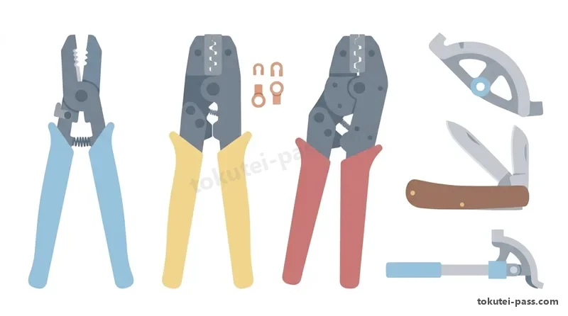
問13(工事と工具の組合せ)および問18(工具の写真鑑別)では、電気工事用工具の正しい用途が問われます。まずケーブル工事では、電線の切断・曲げに使う「ペンチ」、VVFケーブルのシースと絶縁被覆を1丁でむく「VVFストリッパ(ケーブルストリッパ)」、被覆を削り取る「電工ナイフ」を使います。
Question 13 (matching work to tools) and Question 18 (tool photo identification) test the proper use of electrical tools. In cable work, electricians use "lineman's pliers (penchi)" to cut and bend wire, a "VVF cable stripper" to strip both sheath and core insulation in one tool, and an "electrician's knife" to pare insulation.
圧着工具の見分け方は超重要です。リングスリーブ(E形)の圧着には必ず「握り柄(グリップ)が黄色で、ダイス(刻印溝)が○・小・中・大の4つあるリングスリーブ用圧着工具(JIS C 9711)」を使います。柄が赤色のものは「裸圧着端子用」なのでリングスリーブには使えません。
Distinguishing crimping pliers is critical. For crimping ring sleeves (E-type), you must use the "ring sleeve crimping tool (JIS C 9711) with YELLOW handle grips and four die grooves (○, Small, Medium, Large)". Tools with RED handle grips are for "bare crimp terminals (R-type)" and cannot be used on ring sleeves.
金属管工事では、金属管を切断する「金切りのこ(刃は押すときに切れる向きに取り付ける)」、切断後の金属管の内面のバリ(かえり)を削り取る円錐形の刃「リーマ(クリックボールに装着して回す)」、金属管を曲げる長いレバーの「パイプベンダ」を使います。
In metal conduit work, use a "hacksaw (install the blade to cut on the push stroke)" to cut steel pipe, a conical bladed "reamer (mounted in a brace)" to remove interior burrs from the cut pipe end, and a long-lever "pipe bender" to bend steel conduit.
また金属管にねじを切る「ねじ切り器(オスタ形)」、ロックナットやカップリングを挟んで締め付ける口開き調整式の「ウォーターポンププライヤ」、金属管内に最初に通して電線を引き入れる「呼び線(スチールワイヤ)」も金属管工事の必須工具です。
Other essential metal conduit tools include a "pipe threader (Oster-type)" to cut threads on conduit ends, adjustable "water pump pliers" to grip and tighten locknuts and couplings, and a "fish tape (steel wire / yobisen)" fed into the conduit first to pull insulated wires through.
穴あけ工具では、木造の柱や梁に貫通穴をあける手回しの「クリックボールとオーガービット(羽根ぎり)」、鉄製のキャビネットやプルボックスに丸穴をあける円筒鋸刃の「ホールソー(ホルソー)」や油圧式の「ノックアウトパンチャ」、硬質塩化ビニル管(VE)を加熱して曲げる「トーチランプ」を覚えましょう。
For hole-making tools, memorize the hand-cranked "brace and auger bit" for drilling through wooden posts and beams, the cylindrical toothed "hole saw" and hydraulic "knockout puncher" for making round holes in steel enclosures or pull boxes, and the "blowtorch (torch lamp)" for heating and bending rigid PVC (VE) pipe.
Key points
- リングスリーブ用圧着工具は「柄が黄色(刻印:○・小・中・大)」であり、柄が赤色の裸圧着端子用と区別する。
The ring sleeve crimping tool has "YELLOW handles (dies: ○, Small, Medium, Large)"—distinguish it from the RED-handled tool for bare crimp terminals. - 金属管工事の専用工具:切断=金切りのこ、内面のバリ取り=リーマ、曲げ加工=パイプベンダ、ねじ切り=オスタ形ねじ切り器。
Dedicated metal conduit tools: cutting = hacksaw, interior deburring = reamer, bending = pipe bender, threading = Oster-type threader. - 穴あけ・通線工具:木材穴あけ=クリックボールと羽根ぎり、鉄箱穴あけ=ホールソー・ノックアウトパンチャ、管内通線=呼び線。
Drilling & wire-pulling tools: wood boring = brace & auger bit, steel box holes = hole saw / knockout puncher, wire pulling = fish tape (yobisen).
| Word | Meaning |
|---|---|
| リングスリーブ用圧着工具(黄色柄) | ring sleeve crimping tool (yellow handle) |
| VVFストリッパとウォーターポンププライヤ | VVF stripper and water pump pliers |
| パイプベンダとリーマ(面取り器) | pipe bender and pipe reamer (deburring tool) |
| クリックボールとホールソー・ノックアウトパンチャ | brace, hole saw and hydraulic knockout puncher |
| 呼び線(スチールワイヤ) | fish tape / pull wire (yobisen) |
三相かご形誘導電動機の構造・同期速度・始動法と進相コンデンサ
Three-Phase Squirrel-Cage Induction Motors: Structure, Synchronous Speed, Starting & Capacitors
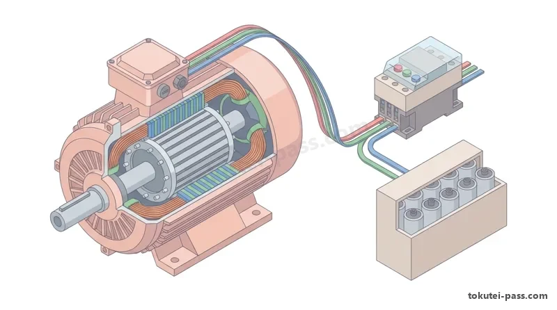
問14では、構造が簡単で丈夫な「三相かご形誘導電動機」の性質が出題されます。固定子の巻線に三相交流を流すと「回転磁界」が生じ、その回転速度を「同期速度Ns(単位:min⁻¹、1分間の回転数)」といいます。
Question 14 tests the characteristics of the "three-phase squirrel-cage induction motor", which has a simple, rugged structure. Supplying three-phase AC to the stator windings creates a "rotating magnetic field", whose rotational speed is called the "synchronous speed Ns (unit: min⁻¹, revolutions per minute)".
同期速度Nsは電源周波数f(Hz)に比例し、磁極数pに反比例する公式「Ns=(120×f)÷p」で求めます。たとえば4極(p=4)の電動機なら、周波数50Hzでは「Ns=120×50÷4=1,500min⁻¹」、60Hzでは「1,800min⁻¹」で回り、50Hzから60Hzになると回転速度は1.2倍に上がります。
Synchronous speed Ns is proportional to supply frequency f (Hz) and inversely proportional to the number of magnetic poles p via "Ns = (120 × f) ÷ p". For a 4-pole motor (p = 4), "Ns = 120 × 50 ÷ 4 = 1,500 min⁻¹" in a 50 Hz region and "1,800 min⁻¹" in a 60 Hz region (changing from 50 Hz to 60 Hz increases speed by 1.2 times).
実際の回転子の回転速度Nは同期速度Nsより数%だけ遅くなり、この遅れの割合を「滑りs」といい「N=Ns×(1−s)」で表されます。また電動機の回転方向を逆転させたいときは、「3本の電源線(R・S・T)のうち、任意の2本だけを入れ替えて接続」します(3本全部を入れ替えると元と同じ向きに回るひっかけに注意)。
The actual rotor speed N is a few percent slower than synchronous speed Ns; this fractional lag is called "slip s", where "N = Ns × (1 − s)". To reverse the rotation direction of a three-phase motor, "swap any 2 of the 3 power supply wires (R, S, T)" (watch out for the trap: swapping all 3 wires cyclically keeps it spinning in the same direction!).
電動機が止まった状態から直接始動(じか入れ始動)すると、定格電流の「4〜8倍」もの大きな始動電流が流れます。これを抑える「スター・デルタ(Y−Δ)始動法」では、始動時に巻線をY結線にすることで、Δ結線でのじか入れ始動に比べて「始動電流も始動トルクも3分の1(1/3)」に減らすことができます。
Starting a motor directly across the line from rest draws a large starting current of "4 to 8 times" rated current. To suppress this, "star-delta (Y-Δ) starting" connects the windings in Y during startup, reducing both "starting current and starting torque to one-third (1/3)" compared with direct-on-line Δ starting.
また誘導電動機はコイルの性質(遅れ力率)を持つため、負荷と「並列」に「進相コンデンサ(SC)」を接続して進み電流を補うことで、回路の力率(cosφ)を1に近づけて改善し、配電線の電流と電力損失を減らすことができます。
Because an induction motor acts inductively (lagging power factor), connecting a "phase-advancing capacitor (SC)" in "parallel" with the motor supplies leading current, improving the circuit power factor (cosφ) closer to 1 and reducing line current and power loss.
Key points
- 同期速度は「Ns=120×f÷p(min⁻¹)」であり、4極機は50Hzで1,500min⁻¹、60Hzで1,800min⁻¹となる。
Synchronous speed is "Ns = 120 × f ÷ p (min⁻¹)"; a 4-pole motor runs at 1,500 min⁻¹ on 50 Hz and 1,800 min⁻¹ on 60 Hz. - 三相誘導電動機の逆転は「3本の電源線のうち2本を入れ替える」/Y−Δ始動法は始動電流を「1/3」に減らす。
Reverse a 3-phase motor by "swapping 2 of the 3 power wires" / Y-Δ starting reduces starting current to "1/3". - 電動機回路の遅れ力率を改善するには、電動機と「並列」に「進相コンデンサ」を接続する。
To improve the lagging power factor of a motor circuit, connect a "phase-advancing capacitor" in "parallel" with the motor. - 【例】6極・周波数 50Hzの三相誘導電動機(すべり s = 0.04) → 同期速度 Ns = 120 × 50 ÷ 6 = 1,000min⁻¹、回転速度 N = 1,000 ×(1 − 0.04)= 960min⁻¹(直入始動電流 90A なら Y−Δ始動時は 90 ÷ 3 = 30A)
Example: A 6-pole, 50Hz 3-phase induction motor (slip s = 0.04) → Synchronous speed Ns = 120 × 50 ÷ 6 = 1,000 min⁻¹, rotor speed N = 1,000 × (1 − 0.04) = 960 min⁻¹ (if direct-on-line starting current is 90A, Y-Δ starting reduces it to 90 ÷ 3 = 30A)
| Word | Meaning |
|---|---|
| 三相かご形誘導電動機 | three-phase squirrel-cage induction motor |
| 同期速度(Ns=120f÷p)と滑り(s) | synchronous speed (Ns = 120f ÷ p) and slip (s) |
| スター・デルタ(Y−Δ)始動法 | star-delta (Y-Δ) starting method |
| 進相コンデンサ(力率改善用) | phase-advancing capacitor (for power factor correction) |
照明器具(LED・蛍光灯・HID)と太陽光発電・蓄電池設備
Lighting Fixtures (LED, Fluorescent, HID), Solar Power and Storage Batteries
問15では照明器具や省エネ機器の特徴も出題されます。現在主流の「LEDランプ(発光ダイオード)」は、白熱電球や蛍光灯に比べて「発光効率(1Wあたりの明るさ:lm/W)が非常に高く、寿命が長い(約40,000時間)」という大きな長所があります。
Question 15 also tests lighting fixtures and energy-saving equipment. Mainstream "LED lamps (light-emitting diodes)" offer major advantages over incandescent bulbs and fluorescent lamps: "extremely high luminous efficacy (brightness per watt: lm/W) and a very long service life (approx. 40,000 hours)".
さらにLEDランプは「スイッチを入れると瞬時に点灯する」「赤外線や紫外線をほとんど含まないため熱線が少なく虫が集まりにくい」「蛍光灯と違って有害な水銀を含まない」「制御用電源装置(LEDドライバ)により力率が高い」といった特徴があります。
Furthermore, LED lamps "light up instantly when switched on", "emit almost no infrared or ultraviolet rays, resulting in less heat radiation and attracting fewer insects", "contain no toxic mercury unlike fluorescent lamps", and "achieve a high power factor via their control power supply unit (LED driver)".
一方、従来の蛍光灯や水銀灯・ナトリウム灯・メタルハライドランプなどの放電灯(HIDランプ)は、放電電流を安定させるために必ず「安定器」と組み合わせて使用します(白熱電球には安定器は不要で、力率は100%です)。
Meanwhile, conventional fluorescent lamps and high-intensity discharge (HID) lamps—such as mercury vapor, sodium vapor, and metal halide lamps—must always be paired with a "ballast (anteiki)" to stabilize discharge current (incandescent bulbs need no ballast and have a 100% power factor).
また住宅用太陽光発電システムでは、屋根の「太陽電池モジュール(パネル)」で発電した「直流電力(DC)」を「接続箱」でまとめ、「パワーコンディショナ(インバータ内蔵)」によって家庭内や商用電力系統と同じ「交流電力(AC100V/200V)」に変換して供給します。
In a residential solar power system, "direct current (DC)" electricity generated by rooftop "solar cell modules (panels)" is gathered in a "junction box" and converted by a "power conditioner (with built-in inverter)" into "alternating current (AC 100 V / 200 V)" synchronized with household wiring and the utility grid.
非常用電源や太陽光発電の蓄電に使われる二次電池(充電して繰り返し使える蓄電池)には、エネルギー密度が高い「リチウムイオン蓄電池」、長寿命な「アルカリ蓄電池(ニッケル水素電池など)」、および「鉛蓄電池」があります(マンガン乾電池やアルカリ乾電池は充電できない一次電池です)。
Secondary batteries (rechargeable storage batteries) used for emergency backup power or solar energy storage include high-energy-density "lithium-ion batteries", long-life "alkaline storage batteries (such as nickel-metal hydride)", and "lead-acid batteries" (manganese and alkaline dry cells are non-rechargeable primary batteries).
Key points
- LEDランプは白熱電球や蛍光灯より「発光効率(lm/W)が高く長寿命」で、水銀を含まず瞬時に点灯する。
LED lamps have "higher luminous efficacy (lm/W) and longer life" than incandescent or fluorescent lamps, contain no mercury, and light instantly. - 太陽光発電では、太陽電池パネルが発電した直流(DC)を「パワーコンディショナ」で交流(AC)に変換する。
In solar power systems, DC electricity generated by solar panels is converted into AC by a "power conditioner". - 機器の正しい組合せ:水銀灯・蛍光灯=「安定器」、誘導電動機=「進相コンデンサ」、太陽電池=「パワーコンディショナ」。
Correct equipment pairings: Mercury/fluorescent lamp = "Ballast"; Induction motor = "Phase-advancing capacitor"; Solar cell = "Power conditioner".
| Word | Meaning |
|---|---|
| 発光効率(lm/W:ルーメン毎ワット) | luminous efficacy (lm/W: lumens per watt) |
| 安定器(放電灯用) | ballast (for discharge lamps) |
| パワーコンディショナ(直流→交流変換) | power conditioner (DC to AC conversion) |
| 二次電池(リチウムイオン蓄電池・鉛蓄電池) | secondary battery (lithium-ion battery, lead-acid battery) |
試験によく出るポイントと覚え方
Frequently Tested Points & Memory Aids
電線の最高許容温度は「IV・VVF=60℃、HIV・EM=75℃、CV=90℃」と15℃刻みで暗記します。配線用遮断器(30A以下)の動作時間は「1.25倍の電流で60分以内、2倍の電流で2分以内(2倍は2分!)」と覚えれば一瞬で選べます。
Memorize maximum allowable wire temperatures in 15°C steps: "IV, VVF = 60°C; HIV, EM = 75°C; CV = 90°C". For MCCB trip times (≤ 30 A), remember: "1.25× current trips within 60 minutes; 2× current trips within 2 minutes (2 times = 2 minutes!)".
スイッチのHとPは「H=ほたる(暗い場所で探すからOFFで光る)」「P=パイロット(換気扇が動いている確認だからONで光る)」。また圧着工具は「黄色グリップ=リングスリーブ用、赤色グリップ=裸圧着端子用」が鉄板の識別点です。
For switches H and P: "H = Hotaru / firefly (glows in the dark to find the switch, so lit when OFF)", "P = Pilot (confirms a fan is running, so lit when ON)". For crimping pliers: "YELLOW handle = Ring sleeves; RED handle = Bare crimp terminals".
電動機は「逆転=3本のうち2本入れ替え」「Y−Δ始動=始動電流1/3」「力率改善=進相コンデンサを並列」。管の加工工具は「金属管のバリ取り=リーマ、曲げ=パイプベンダ」「合成樹脂管(VE)の曲げ=トーチランプ」の組み合わせが頻出です。
For 3-phase motors: "Reverse rotation = swap 2 of 3 wires", "Y-Δ starting = starting current becomes 1/3", "Power factor improvement = parallel phase-advancing capacitor". For conduit tools: "Metal pipe deburring = reamer, bending = pipe bender; PVC pipe (VE) bending = blowtorch".
Key points
- 最高許容温度:IV・VVF・VVR=60℃ / HIV・EM-IE・EM-EEF=75℃ / CVケーブル=90℃。
Maximum allowable temperature: IV, VVF, VVR = 60°C / HIV, EM-IE, EM-EEF = 75°C / CV cable = 90°C. - 遮断器動作時間(定格30A以下):定格の1.25倍=60分以内、定格の2倍=2分以内(2倍は2分)。
Breaker trip time (rated ≤ 30 A): 1.25× rated current = within 60 min; 2× rated current = within 2 min (2× is 2 min). - スイッチとコンセント:H(位置表示)=OFFで点灯、P(確認表示)=ONで点灯、LK=抜け止め形、WP=防雨形。
Switches & Outlets: H (location indicator) = lit when OFF; P (pilot indicator) = lit when ON; LK = twist-lock; WP = weatherproof. - 圧着・配管工具:リングスリーブ用=黄色柄、金属管面取り=リーマ、金属管曲げ=パイプベンダ、異種管接続=コンビネーションカップリング。
Crimping & Conduit tools: Ring sleeve plier = YELLOW handle; pipe deburring = reamer; steel pipe bending = pipe bender; dissimilar pipes = combination coupling. - 三相誘導電動機:同期速度 Ns=120f÷p、逆転=3本中2本入れ替え、Y−Δ始動電流=1/3、進相コンデンサ=並列接続。
3-Phase Induction Motor: Synchronous speed Ns = 120f ÷ p; reverse = swap 2 of 3 wires; Y-Δ starting current = 1/3; phase-advancing capacitor = parallel.
| Word | Meaning |
|---|---|
| 最高許容温度(60℃・75℃・90℃) | maximum allowable temperature (60°C, 75°C, 90°C) |
| 2倍電流は2分以内動作 | 2× current trips within 2 minutes |
| 黄色柄のリングスリーブ用圧着工具 | yellow-handled ring sleeve crimping tool |
| ゴムブッシング(ボックス穴)と絶縁ブッシング(金属管端) | rubber bushing (box knockout) and insulating bushing (metal pipe end) |
Equipment, Devices, Materials & Tools
Practice this chapter in the appOfficial references
- 一般財団法人 電気技術者試験センター「第二種電気工事士試験(電気機器・配線器具並びに電気工事用の材料及び工具)」 — https://www.shiken.or.jp/
- 日本産業規格「JIS C 3342 600Vビニル絶縁ビニルシースケーブル(VVF)」「JIS C 9711 屋内配線用電線接続工具」 — https://www.jisc.go.jp/