
Electrical Construction Methods
電気工事の施工方法
Class 2 Electrician 第二種電気工事士 (written exam) · 第二種電気工事士(学科試験) · Written by Tokutei Pass based on the official study texts; not copied verbatim.
電線の接続基準とリングスリーブ・差込形コネクタ
Wire Connection Standards, Ring Sleeves, and Push-in Connectors
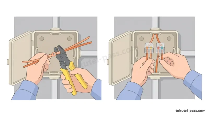
電線を相互に接続する際は次の4基準を守ります。①電気抵抗を増加させないこと、②機械的強さ(引張強さ)を20%以上減少させないこと、③接続管(スリーブ)等の器具を使うかろう付けすること、④その電線の絶縁物と同等以上の効力があるもので十分被覆することです。
When connecting electrical wires together, all four of the following standards must be strictly observed: ① Do not increase the electrical resistance of the wire; ② Do not reduce the mechanical strength (tensile strength) of the wire by 20% or more; ③ Use connecting devices such as sleeves or connectors at the joint, or braze/solder the joint; ④ Cover the joint thoroughly with insulation equivalent to or better than the wire's original insulation.
リングスリーブ(E形)による圧着接続では、必ず「黄色柄のリングスリーブ用圧着工具(JIS C 9711適合品)」を使用します。赤色柄の裸圧着端子用工具は絶対に使用できません。スリーブのサイズ(小・中・大)とダイスの刻印(○・小・中・大)は、接続する単線の本数と太さによって厳密に決まっています。
For crimp connections using E-type ring sleeves, you must always use the yellow-handled crimping tool specifically for ring sleeves (conforming to JIS C 9711). Red-handled crimping tools for bare crimp terminals must never be used. Both the sleeve size (Small, Medium, Large) and the die stamp mark (○, 小, 中, 大) are strictly determined by the number and diameter of the solid wires being joined.
スリーブと刻印を簡単に求めるには「点数法」を使います。直径1.6mmの電線を「1点」、直径2.0mm(断面積3.5mm²相当)の電線を「2点」として合計点数を計算します。唯一の特例として、「1.6mm×2本(合計2点)」のときだけ「小スリーブ」を使い、一番小さなダイスで「○(極小)」の刻印を押します。
To quickly determine the sleeve size and stamp mark, use the Point Method: count each 1.6mm diameter wire as 1 point and each 2.0mm diameter wire (equivalent to 3.5mm² cross-section) as 2 points, then add them up. As the sole special exception, when joining two 1.6mm wires (1.6mm × 2 wires = 2 points total), use a Small sleeve (小) and crimp it with the smallest die to leave the ○ (extra-small) stamp mark.
それ以外の組み合わせでは、合計3〜4点(例:1.6mm×3本=3点、1.6mm×4本=4点、1.6mm×1本+2.0mm×1本=3点、1.6mm×2本+2.0mm×1本=4点、2.0mm×2本=4点)はすべて「小スリーブ」を使用し、刻印も「小」になります。
For all other combinations totaling 3 to 4 points (e.g., 1.6mm × 3 = 3 pts; 1.6mm × 4 = 4 pts; 1.6mm × 1 + 2.0mm × 1 = 3 pts; 1.6mm × 2 + 2.0mm × 1 = 4 pts; 2.0mm × 2 = 4 pts), always use a Small sleeve (小) and crimp with the 小 (Small) stamp mark.
合計5〜8点(1.6mm×3本+2.0mm×1本=5点、2.0mm×3本=6点、2.0mm×4本=8点など)はすべて「中スリーブ」を使い、刻印も「中」になります。差込形コネクタを使う場合は、ゲージに合わせて心線をむき、奥まで差し込んで先端が見えることを確認します(テープ巻きは不要です)。
For combinations totaling 5 to 8 points (e.g., 1.6mm × 3 + 2.0mm × 1 = 5 pts; 1.6mm × 1 + 2.0mm × 2 = 5 pts; 2.0mm × 3 = 6 pts; 2.0mm × 4 = 8 pts), always use a Medium sleeve (中) and crimp with the 中 (Medium) stamp mark. When using push-in connectors, strip the core wires straight to match the strip gauge, push them all the way in, and verify that the wire tips are visible through the transparent end (insulating tape is not required).
Key points
- 電線接続時は電気抵抗を増加させず、引張強さを20%以上減少させないこと
Wire connections must not increase electrical resistance and must not reduce tensile strength by 20% or more - リングスリーブは黄色柄の圧着工具を使用し、1.6mm=1点・2.0mm=2点で計算する
Use the yellow-handled crimping tool for ring sleeves; calculate using 1.6mm = 1 point and 2.0mm = 2 points - 1.6mm×2本のみ小スリーブで刻印「○」、3〜4点は小スリーブで刻印「小」
Only 1.6mm × 2 wires uses a Small sleeve with the ○ mark; 3 to 4 points use a Small sleeve with the 小 mark - 5〜8点(2.0mm×3本や1.6mm×3本+2.0mm×1本など)は中スリーブで刻印「中」
5 to 8 points (such as 2.0mm × 3 wires or 1.6mm × 3 + 2.0mm × 1) use a Medium sleeve with the 中 mark - 【例】リングスリーブの点数計算(1.6mm=1点、2.0mm=2点) → 1.6mm×2本+2.0mm×1本は 1×2+2×1=4点(小スリーブ・刻印「小」)、1.6mm×2本+2.0mm×2本は 1×2+2×2=6点(中スリーブ・刻印「中」)
Example: Ring sleeve point calculation (1.6mm = 1 pt, 2.0mm = 2 pts) → Joining 1.6mm × 2 + 2.0mm × 1 gives 1 × 2 + 2 × 1 = 4 pts (Small sleeve, mark 小); joining 1.6mm × 2 + 2.0mm × 2 gives 1 × 2 + 2 × 2 = 6 pts (Medium sleeve, mark 中)
| Word | Meaning |
|---|---|
| 引張強さ | tensile strength |
| リングスリーブ | ring sleeve (E-type crimp sleeve) |
| 刻印 | die stamp mark / crimp mark |
| 差込形コネクタ | push-in connector |
| ろう付け | brazing / soldering |
場所別の低圧屋内配線工事の可否
Permissible Low-Voltage Indoor Wiring Methods by Location
低圧屋内配線の工事方法は、施工する場所の条件によって使用できる種類が制限されています。試験では「展開した場所(露出場所)」「点検できる隠ぺい場所(点検口のある天井裏など)」「点検できない隠ぺい場所(壁の内部や点検口のない天井裏)」「湿気または水気の多い場所」の組合わせが毎年出題されます。
Low-voltage indoor wiring methods are restricted depending on the conditions of the installation location. Every exam tests combinations of four locations: exposed locations (open surfaces), inspectable concealed locations (such as above a ceiling with an inspection hatch), uninspectable concealed locations (inside walls or ceilings without an inspection hatch), and damp or wet locations.
「ケーブル工事」「合成樹脂管工事(CD管を除く)」「金属管工事」「2種金属製可とう電線管工事」の4つは万能であり、展開した場所、点検できる隠ぺい場所、点検できない隠ぺい場所、湿気・水気の多い場所のすべてで施工することができます。
Four methods — cable work, synthetic resin conduit work (excluding CD conduit), metal conduit work, and Type 2 flexible metal conduit work — are universal and can be installed in all locations: exposed locations, inspectable concealed locations, uninspectable concealed locations, and damp or wet locations.
一方、「ライティングダクト工事」「金属ダクト工事」「バスダクト工事」「平形保護層工事」は、点検できない隠ぺい場所では絶対に施工できません(展開した場所や点検できる場所であり、かつ乾燥した場所でのみ施工可能です)。
Conversely, lighting duct work, metal duct work, bus duct work, and flat protective layer wiring can never be installed in uninspectable concealed locations (they are permitted only in exposed or inspectable concealed locations that are also dry).
また、「金属線ぴ工事(メタルモール)」と「がいし引き工事」は、点検できない隠ぺい場所では施工できません。さらに金属線ぴ工事は湿気や水気の多い場所でも施工できません(がいし引き工事は展開した場所であれば湿気の多い場所でも施工できます)。
Furthermore, metal molding work (metal raceways) and knob-and-tube (insulator) wiring cannot be installed in uninspectable concealed locations. In addition, metal molding work cannot be used in damp or wet locations (whereas knob-and-tube wiring can be used in damp locations provided the location is exposed).
使用電圧が300V以下の「小勢力回路(チャイムやインターホンなど、最大使用電圧60V以下の回路)」を除き、低圧屋内配線にコード(ビニルコードなど)を直接造営材に固定して配線することは禁止されています。
Except for small-power circuits (such as doorbells or intercoms with a maximum operating voltage of 60V or less) in low-voltage installations of 300V or less, fastening flexible cords (such as vinyl cords) directly to building surfaces for indoor wiring is strictly prohibited.
Key points
- ケーブル・合成樹脂管(CD管除く)・金属管・2種金属可とう管はすべての場所で施工可能
Cable, synthetic resin conduit (except CD), metal conduit, and Type 2 flexible metal conduit are allowed in all locations - 金属ダクト・ライティングダクト・バスダクトは「点検できない隠ぺい場所」や「湿気・水気場所」で不可
Metal ducts, lighting ducts, and bus ducts are prohibited in uninspectable concealed locations and damp/wet locations - 金属線ぴ工事は「点検できない隠ぺい場所」および「湿気・水気の多い場所」で施工不可
Metal molding work is prohibited in uninspectable concealed locations and in damp or wet locations - がいし引き工事は「点検できない隠ぺい場所」で施工不可
Knob-and-tube (insulator) wiring is prohibited in uninspectable concealed locations
| Word | Meaning |
|---|---|
| 展開した場所 | exposed location (open surface) |
| 隠ぺい場所 | concealed location (inside walls or ceilings) |
| がいし引き工事 | knob-and-tube (insulator) wiring |
| 金属線ぴ工事 | metal molding (surface raceway) work |
ケーブル工事・地中埋設配線・引込線の基準
Standards for Cable Work, Underground Wiring, and Service Drops
ケーブル工事でVVFケーブルやCVケーブルを造営材の側面または下面に沿って水平に取り付ける場合、支持点間の距離は「2m以下」としなければなりません(接触防護措置を施した垂直配線では「6m以下」まで認められます)。また、ケーブルの屈曲半径(曲げ半径)は、ケーブル外径(平形は短径)の「6倍以上」とします。
In cable work, when running VVF or CV cables horizontally along the side or underside of building structures, the distance between support points must be 2m or less (up to 6m or less is permitted for vertical runs protected against physical contact). Additionally, the bending radius of the cable must be at least 6 times the outer diameter of the cable (or the minor axis for flat cables).
ケーブルが弱電流電線(電話線やLANケーブルなど)や水管・ガス管と接近・交差する場合は、直接接触しないように離して施設します。また、コンクリートに直接埋設する場合は、MIケーブルや専用の埋設用ケーブルを除き、管(CD管やPF管など)やトラフに収めて保護しなければなりません。
When cables run close to or cross weak-current wires (telephone lines, LAN cables) or water and gas pipes, they must be separated so they do not make direct contact. When burying cables directly in concrete, except for MI cables or specially rated concrete-burial cables, they must be enclosed and protected inside conduits (such as CD or PF conduits) or troughs.
屋外の「地中電線路(直接埋設式)」では、自動車などの重量物の圧力を受ける場所は「1.2m以上」、圧力を受けない場所は「0.6m以上」の深さに埋設し、トラフ等で保護します。なお、地中配線にOWやIV電線は使えず、CVケーブル等を使います。
For outdoor underground cable lines (direct burial method), burial depth standards are critical: the depth must be 1.2m or more in places subject to heavy vehicular pressure, and 0.6m or more in places not subject to heavy pressure, with protective covers (concrete troughs or plates) installed to shield the cable from impact. Note that OW (outdoor weatherproof vinyl wire) and IV wires cannot be used underground (use CV cables, etc.).
架空電線路から建物へ電気を引き込む「低圧架空引込線」では、地表上の高さが原則「4m以上」(道路を横断する場合などは必ず4m以上)必要です。ただし、技術上やむを得ない場合において交通に支障がないときは「2.5m以上」とすることができます。引込線にはDV(引込用ビニル絶縁電線)やOW(直径2.0mm以上)などが使われます。
For low-voltage overhead service drops bringing power from utility poles to a building, the height above ground must in principle be 4m or more (always 4m or more when crossing a road). However, where technically unavoidable and where it poses no obstruction to traffic, the height may be reduced to 2.5m or more. DV wires or OW wires (2.0mm diameter or larger) are commonly used for service drops.
Key points
- ケーブル工事の支持点間距離は2m以下(垂直は6m以下)、曲げ半径は外径(短径)の6倍以上
Cable support interval is 2m or less (6m or less vertically), and bending radius is at least 6 times the outer diameter (minor axis) - ケーブルは弱電流電線・水管・ガス管と接触しないように施設する
Cables must be installed so that they do not contact weak-current wires, water pipes, or gas pipes - 地中埋設深さは重量物の圧力がある場所で1.2m以上、ない場所で0.6m以上(CVケーブル等を使用)
Underground burial depth: 1.2m or more under heavy pressure, 0.6m or more without heavy pressure (use CV cables, etc.) - 低圧架空引込線の高さは原則4m以上、交通に支障がない場合は2.5m以上
Low-voltage overhead service drop height: 4m or more in principle, or 2.5m or more where there is no obstruction to traffic
| Word | Meaning |
|---|---|
| 支持点間距離 | distance between support points |
| 屈曲半径 | bending radius |
| 直接埋設式 | direct burial method |
| 架空引込線 | overhead service drop |
合成樹脂管工事と金属管工事の施工基準
Construction Standards for Synthetic Resin Conduits and Metal Conduits
合成樹脂管工事で硬質ポリ塩化ビニル電線管(VE管)を使用する場合、管の支持点間の距離は「1.5m以下」とします。管相互をTSカップリングで接続する際の差し込み深さは、接着剤を使用しない場合は管外径の「1.2倍以上」、接着剤を使用する場合は管外径の「0.8倍以上」とします。
In synthetic resin conduit work using rigid polyvinyl chloride conduits (VE conduits), the distance between conduit support points must be 1.5m or less. When joining conduits together with a TS coupling, the insertion depth must be at least 1.2 times the outer diameter of the conduit when no adhesive is used, or at least 0.8 times the outer diameter when adhesive is used.
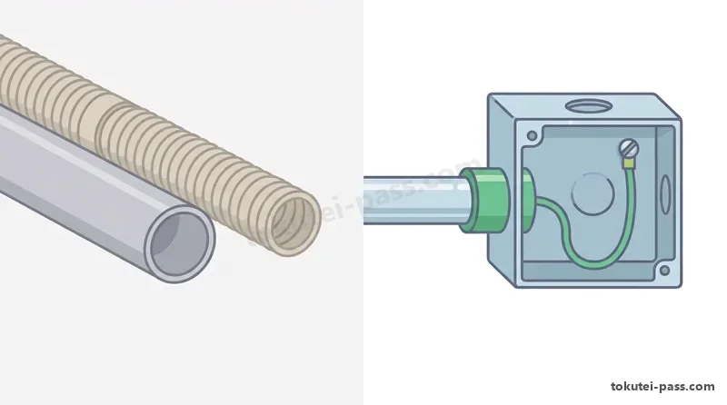
合成樹脂製可とう電線管のうち、オレンジ色のCD管は自己消火性がないため、コンクリートに直接埋設する場合(または専用の不燃性カバー内)にしか使用できません。ベージュ色や黒色のPF管は自己消火性があるため、隠ぺい場所や露出場所にも使用できます(管の支持点間距離は1.0m以下)。
Among flexible synthetic resin conduits, orange CD conduits are not self-extinguishing (flame-retardant) and may only be used when embedded directly in concrete (or inside dedicated non-combustible covers). Beige or black PF conduits are self-extinguishing and can be used in both concealed and exposed locations (with a support interval of 1.0m or less).
金属管工事では、管の支持点間距離は「2m以下」とします。電線の被覆が金属管の切り口で傷つくのを防ぐため、管の端(管端)には必ず「絶縁ブッシング」を取り付けます。また、管とアウトレットボックスを電気的に接続するため、ボンド線やロックナットで確実に導通を確保し、管にはD種接地工事を施します。
In metal conduit work, the distance between support points must be 2m or less. To prevent wire insulation from being damaged by the sharp edges of the cut conduit, an insulating bushing must always be attached to the conduit end. Additionally, bond wires or locknuts must be used to ensure electrical continuity between conduits and outlet boxes, and Class D grounding must be applied to the conduit.
合成樹脂管内および金属管内では、電線に接続点を設けることは絶対に禁止されています(接続は必ずボックス内で行います)。また、管内にはIV電線などの絶縁電線を収めますが、「OW(屋外用ビニル絶縁電線)」は使用できません。さらに、直径3.2mmを超える太い電線は「より線」でなければなりません。
Inside both synthetic resin conduits and metal conduits, making wire splices or joints is strictly prohibited (all connections must be made inside boxes). Insulated wires such as IV wires are pulled into conduits, but OW (outdoor weatherproof) wires cannot be used inside conduits. Furthermore, wires with a diameter exceeding 3.2mm must be stranded wires.
金属管に交流回路の電線を収める場合は、電磁的不平衡による渦電流で金属管が過熱するのを防ぐため、必ず「同一回路のすべての電線(単相2線式なら往復2本、三相3線式なら3本すべて)」を1本の金属管にまとめて収め、電磁的平衡を保たなければなりません(合成樹脂管は磁性体ではないため別々の管に入れても発熱しません)。
When placing AC circuit wires inside a metal conduit, to prevent the conduit from overheating due to eddy currents caused by electromagnetic imbalance, all wires belonging to the same circuit (both wires for single-phase 2-wire, or all three wires for three-phase 3-wire) must be placed together inside the same metal conduit to maintain electromagnetic balance (synthetic resin conduits are non-magnetic, so placing wires in separate conduits does not cause heating).
Key points
- VE管の支持点は1.5m以下、差し込み深さは接着剤なし1.2倍以上・接着剤あり0.8倍以上
VE conduit support interval is 1.5m or less; insertion depth is 1.2× outer diameter without adhesive, or 0.8× with adhesive - CD管は自己消火性がないためコンクリート直接埋設のみ可、PF管は露出・隠ぺいとも可
CD conduits lack self-extinguishing properties and are only for direct concrete burial; PF conduits can be used exposed or concealed - 管内では電線の接続禁止、OW電線の使用禁止、単線は直径3.2mm以下まで
Inside conduits: wire joints are prohibited, OW wires are prohibited, and solid wires are limited to 3.2mm diameter or less - 金属管の管端には絶縁ブッシングを付け、交流回路は同一回路の全電線を同一管内に収める
Attach insulating bushings to metal conduit ends, and place all wires of the same AC circuit inside the same metal conduit
| Word | Meaning |
|---|---|
| 絶縁ブッシング | insulating bushing |
| 自己消火性 | self-extinguishing (flame-retardant) property |
| 電磁的平衡 | electromagnetic balance |
| ボンド線 | bond wire (bonding jumper) |
ダクト・線ぴ工事と点滅器(スイッチ)の接続ルール
Duct and Raceway Work, and Switch Connection Rules
金属ダクト工事では、ダクトの支持点間距離を「3m以下」とし、ダクトにはD種接地工事を施します。ダクト内に収める電線の断面積(絶縁被覆を含む総断面積)は、ダクト内部断面積の「20%以下」(制御回路や出退表示灯回路のみの電線なら「50%以下」)としなければなりません。
In metal duct work, the distance between support points must be 3m or less, and Class D grounding must be applied to the duct. The total cross-sectional area of wires (including insulation) inside a metal duct must be 20% or less of the internal cross-sectional area of the duct (or up to 50% or less for control circuits and indicator lamp circuits only).
ライティングダクト工事では、ダクトの支持点間距離を「2m以下」とし、ダクトの開口部(溝)は必ず「下向き」に施設します(横向きはほこりがたまるため原則不可)。また、ダクトの終端部はエンドキャップで閉塞し、対地電圧150V以下で長さ4m以下の場合を除きD種接地工事を施します。
In lighting duct work, the distance between support points must be 2m or less, and the opening (slot) of the duct must face downward (facing sideways is generally prohibited because dust accumulates). The end of the duct must be closed off with an end cap, and Class D grounding must be applied unless the voltage to ground is 150V or less and the duct length is 4m or less.
2種金属製可とう電線管(プリカチューブ)の支持点間距離は「1.5m以下」であり、金属管との接続には「コンビネーションカップリング」、ボックスとの接続には「ストレートボックスコネクタ」を使用します。また、床面に埋め込むフロアダクト工事では、電線相互の接続をジャンクションボックス内で行い、D種接地工事を施します。
Type 2 flexible metal conduits (Plica tubes) require a support interval of 1.5m or less; use a combination coupling to connect them to rigid metal conduits, and a straight box connector to connect them to boxes. In floor duct work embedded in floors, wire connections must be made inside junction boxes and Class D grounding must be applied.
配線器具の施工で最も重要なルールは単極スイッチの位置です。単極スイッチは必ず「非接地側電線(黒色)」に入れ、「接地側電線(白色)」は直接負荷(照明の受金側)へつなぎます。白線にスイッチを入れると、切っても照明に電圧がかかり電球交換時に感電するため厳禁です。
The most important safety rule when installing wiring devices is the placement of single-pole switches. A single-pole switch must always be placed in the ungrounded conductor (black wire), while the grounded conductor (white wire) must be connected directly to the load (specifically to the screw shell side of a lamp socket). Placing a switch in the grounded (white) wire is strictly prohibited because voltage remains applied to the light fixture even when the switch is turned off, creating an electric shock hazard when changing bulbs.
Key points
- 金属ダクトの支持点は3m以下、電線断面積はダクト内の20%以下(制御回路は50%以下)
Metal duct support interval is 3m or less; wire cross-section must be 20% or less of duct area (50% or less for control circuits) - ライティングダクトの支持点は2m以下、開口部は下向きとし、終端を閉塞する
Lighting duct support interval is 2m or less, with the opening facing downward and the end closed off - 2種金属製可とう電線管の支持点は1.5m以下で、金属管とはコンビネーションカップリングで接続
Type 2 flexible metal conduit support interval is 1.5m or less, connected to rigid metal conduit via a combination coupling - 単極スイッチは必ず非接地側電線(黒線)に入れ、接地側(白線)は直接負荷へつなぐ
Single-pole switches must always be placed in the ungrounded (black) wire; the grounded (white) wire goes directly to the load
| Word | Meaning |
|---|---|
| 金属ダクト | metal duct |
| ライティングダクト | lighting duct (track lighting busway) |
| 非接地側電線 | ungrounded conductor (live/hot black wire) |
| 受金 | lamp socket screw shell |
D種接地工事の基準(接地抵抗値と接地線の太さ)
Class D Grounding Standards (Ground Resistance and Grounding Wire Size)
電気機器の金属製外箱や金属管に漏電が生じた際、感電事故を防ぐために地面(大地)と電気的に接続する工事を「接地工事(アース工事)」といいます。使用電圧が「300V以下」の低圧機器や金属管には「D種接地工事」を施します(300Vを超える低圧にはC種接地工事を施します)。
To prevent electric shock accidents in the event of electrical leakage to the metal enclosures of electrical equipment or metal conduits, connecting them electrically to the earth is called grounding work. Low-voltage equipment and metal conduits operating at 300V or less require Class D grounding (low-voltage equipment operating above 300V requires Class C grounding).
D種接地工事における接地抵抗値は、原則として「100Ω以下」に保たなければなりません(C種接地工事は原則10Ω以下です)。
In Class D grounding work, the ground resistance value must in principle be maintained at 100Ω or less (for Class C grounding work, it is 10Ω or less in principle).
ただし、電路に地絡(漏電)が生じたときに「0.5秒以内」に自動的に電路を遮断する装置(漏電遮断器)を施設した場合は、D種(およびC種)接地工事の接地抵抗値を「500Ω以下」まで緩和することができます。
However, if the circuit is equipped with a device (an earth leakage circuit breaker) that automatically interrupts the circuit within 0.5 seconds when a ground fault occurs, the allowable ground resistance value for Class D (and Class C) grounding can be relaxed to 500Ω or less.
D種接地工事の接地線(緑色のIV線など)には、故障時の電流を安全に通す「直径1.6mm以上の軟銅線(より線は断面積2.0mm²以上)」を使います。なお、移動用電気機器の接地線には断面積0.75mm²以上のコードやキャブタイヤケーブルの1心を使います。
The grounding wire (such as a green IV wire) used for Class D grounding must safely carry fault current and must be an annealed copper wire with a diameter of 1.6mm or more (or a nominal cross-sectional area of 2.0mm² or more for stranded wire), or a conductor of equivalent or greater strength and thickness. Note that for portable electrical equipment, one core of a multi-core cord or cabtyre cable with a cross-section of 0.75mm² or more is used as the grounding conductor.
Key points
- 300V以下の低圧機器・金属管にはD種接地工事を施す(300V超はC種)
Apply Class D grounding to low-voltage equipment and metal conduits of 300V or less (Class C for over 300V) - D種接地工事の接地抵抗値は原則100Ω以下
The ground resistance value for Class D grounding is 100Ω or less in principle - 0.5秒以内に動作する漏電遮断器を取り付けた場合は500Ω以下に緩和される
If an earth leakage breaker operating within 0.5 seconds is installed, ground resistance is relaxed to 500Ω or less - D種接地線の太さは「直径1.6mm以上の軟銅線」を使用する
Class D grounding wires must be annealed copper wire with a diameter of 1.6mm or more
| Word | Meaning |
|---|---|
| D種接地工事 | Class D grounding work (for low voltage 300V or less) |
| 接地抵抗値 | ground resistance value |
| 地絡 | ground fault (earth leakage) |
| 軟銅線 | annealed copper wire (soft copper wire) |
D種接地工事を省略できる場合と省略できない場合
When Class D Grounding Can and Cannot Be Omitted
機器の金属製外箱でD種接地を省略できる代表例は次の3つです。①「乾燥した場所」に施設する「対地電圧150V以下(単相100V・200V)」の機器、②「二重絶縁構造」の機器、③電源側に絶縁変圧器(2次300V以下・3kVA以下)を設けた機器です。
A very frequent exam topic is the conditions under which Class D grounding can be omitted. For metal enclosures of electrical equipment, three representative cases allow omitting Class D grounding: ① Equipment with a voltage to ground of 150V or less (such as single-phase 100V or single-phase 3-wire 200V) installed in a dry location; ② Double-insulated equipment (marked with the concentric square symbol 回); ③ Equipment supplied through an isolating transformer (secondary voltage 300V or less, capacity 3kVA or less).
また、「水気のある場所以外の場所」において、電路に「定格感度電流15mA以下、動作時間0.1秒以下(高速形)」の電流動作形漏電遮断器を施設した場合も、D種接地工事を省略できます(前節の「0.5秒以内で500Ω以下」の数値と混同しないよう注意してください)。
Furthermore, in locations other than wet locations, if the circuit is protected by a current-operated earth leakage circuit breaker with a rated sensitivity current of 15mA or less and an operating time of 0.1 seconds or less (high-speed type), Class D grounding may also be omitted (be careful not to confuse these numbers with the 0.5-second / 500Ω rule from the previous section).
金属管や金属製可とう電線管でD種接地を省略できるのは次の2つです。①管の長さが「4m以下」で「乾燥した場所」に施設する場合(三相200Vも可)、②「直流300Vまたは交流対地150V以下」で管の長さが「8m以下」かつ「簡易接触防護または乾燥場所」に施設する場合です。
For metal conduits or flexible metal conduits, Class D grounding can be omitted in two cases: ① When the conduit length is 4m or less and it is installed in a dry location (permitted even for three-phase 200V as long as the voltage is 300V or less); ② In circuits of 300V DC or 150V AC to ground or less, when the conduit length is 8m or less and it is either protected against simple contact or installed in a dry location.
逆に、「水気のある場所(厨房・浴室・屋外・ぬれた土間)」や「湿気の多い場所」では、単相100V機器や4m以下の金属管でもD種接地を省略できません(二重絶縁機器を除く)。「水気」「湿気」「屋外」とあれば即座に「省略不可」と判断しましょう。
Conversely, in wet locations (commercial kitchens, bathrooms, outdoors, wet dirt floors, etc.) or damp locations, Class D grounding can never be omitted—even for single-phase 100V equipment or metal conduits shorter than 4m (except for double-insulated equipment, etc.). Whenever an answer choice mentions a wet location (水気のある場所), damp location (湿気の多い場所), or outdoors (屋外), immediately judge that grounding cannot be omitted.
Key points
- 乾燥した場所の対地電圧150V以下の機器、および二重絶縁構造の機器はD種接地を省略可
Equipment of 150V or less to ground in a dry location, and double-insulated equipment, can omit Class D grounding - 水気のない場所で「感度電流15mA以下・動作時間0.1秒以下」の漏電遮断器があれば省略可
In non-wet locations, an earth leakage breaker with sensitivity 15mA or less and operating time 0.1s or less allows omitting Class D grounding - 金属管は「乾燥場所で4m以下」または「対地150V以下で乾燥場所(または接触防護)かつ8m以下」なら省略可
Metal conduits can omit Class D grounding if 4m or less in a dry location, or 8m or less (150V or less to ground + dry location or contact protection) - 「水気のある場所・湿気の多い場所・屋外」では原則としてD種接地工事を省略できない
In wet locations, damp locations, or outdoors, Class D grounding cannot in principle be omitted
| Word | Meaning |
|---|---|
| 二重絶縁構造 | double-insulated construction |
| 定格感度電流 | rated sensitivity current |
| 動作時間 | operating time (tripping time) |
| 絶縁変圧器 | isolating transformer |
技能試験(実技)の概要と欠陥(不合格)の判断基準
Overview of the Practical Skill Exam and Defect (Fail) Criteria
第二種電気工事士の免状を取得するには、学科試験に合格した後、実際に工具を使って配線作品を組み立てる「技能試験(実技試験)」に合格しなければなりません。試験時間は「40分」で、年初に試験センターから事前公表される「候補問題13問」の中から1問が出題されます。
To obtain the Second-Class Electrician license, after passing the written exam, you must pass the Practical Skill Exam, where you assemble a wiring project using hand tools. The time limit is 40 minutes, and one problem is selected from the 13 Candidate Problems publicly released at the beginning of each year by the examination center.
受験者が持参する指定工具は、ペンチ、ドライバ(プラス・マイナス)、電工ナイフ、スケール、ウォーターポンププライヤ、リングスリーブ用圧着工具(黄色柄)であり、これに加えて作業を劇的に速くする「VVFストリッパ」と「合格クリップ」の持ち込みが認められています(電動工具は使用禁止です)。
The designated tools examinees must bring are pliers, screwdrivers (Phillips and flathead), an electrician's knife, a ruler/scale, water pump pliers, and a yellow-handled ring sleeve crimping tool. In addition, bringing a VVF stripper and Gokaku clips—which dramatically speed up assembly—is permitted (power tools are prohibited).
技能試験の採点は減点方式ではなく、「欠陥が1つでもあれば一発不合格、欠陥がゼロなら合格」という基準で行われます。この欠陥基準は学科試験の施工問題としても出題されるため、両方の対策として確実に理解しておく必要があります。
Grading on the practical exam is not based on partial point deductions; instead, a single defect results in immediate failure, and zero defects results in passing. Because these defect criteria are also tested on the written exam, mastering them prepares you for both exams.
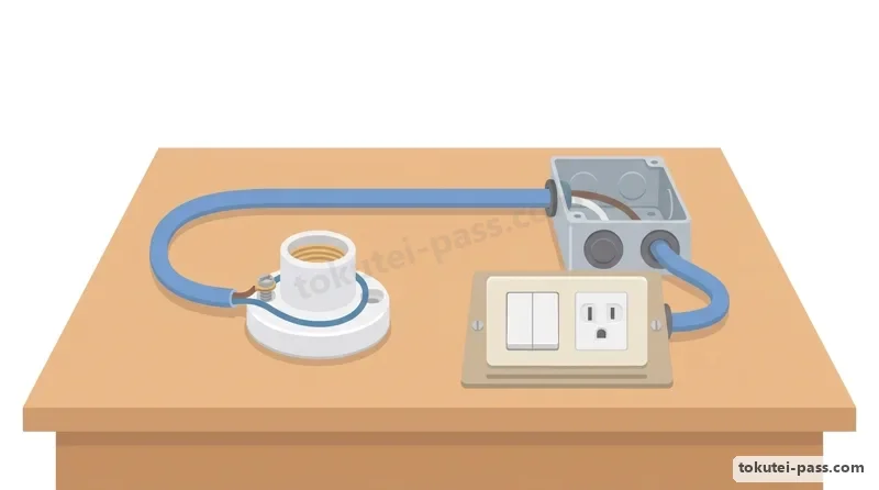
器具結線の欠陥は、①誤配線や極性間違い(コンセントWに白線以外やレセプタクル受金に黒線を接続)、②埋込器具から心線が2mm以上露出または被覆噛み込み、③レセプタクル等のねじ止めが左巻き、3/4周未満、重なり、台座外のシースなし等です。
Major defects in device termination include: ① Miswiring that differs from the diagram or reversed polarity (inserting a non-white wire into the W terminal of a receptacle, connecting the black wire to the screw shell of a lamp receptacle, etc.); ② Core wire exposed by 2mm or more from a flush-mounted device terminal, or insulation caught inside the terminal; ③ On screw terminals of a lamp receptacle or exposed receptacle, wrapping the wire counterclockwise (left-handed loop), wrapping less than 3/4 of a turn, overlapping wire turns, or failing to bring the cable sheath inside the base.
電線接続の欠陥は、①リングスリーブのサイズ・刻印(○・小・中)間違い、②スリーブ上端から心線が出ない又は5mm以上露出、下端から10mm以上露出、③差込形コネクタ先端から心線が見えない又は下部から露出、④ゴムブッシング付け忘れや止めねじのねじ切り忘れ等です。
Major defects in wire splicing include: ① Using the wrong ring sleeve size or wrong crimp stamp mark (○, 小, 中); ② Core wires not protruding at all from the top of the sleeve or protruding 5mm or more, or core wires exposed 10mm or more below the bottom of the sleeve; ③ Core wire tips not visible at the top of a push-in connector (insufficient insertion) or bare wire exposed below the bottom of the connector; ④ Forgetting to attach a rubber bushing to an outlet box or forgetting to shear off the set screw head on a threadless conduit fitting.
Key points
- 技能試験は制限時間40分、事前公表される候補問題13問から1問が出題される
The practical skill exam lasts 40 minutes and tests 1 problem chosen from 13 pre-published candidate problems - 欠陥が1か所でもあれば不合格となる(誤配線・極性間違い・刻印間違いは一発アウト)
Even a single defect results in failure (miswiring, wrong polarity, or wrong crimp mark is an automatic fail) - リングスリーブ上端から心線が出ない、または5mm以上露出、下端から10mm以上露出は欠陥
For ring sleeves: wires not protruding from the top, protruding 5mm or more from the top, or exposed 10mm or more below the bottom are defects - ランプレセプタクルのねじ止めは必ず右巻き(時計回り)にし、接地側(白線)を受金側のねじに接続する
Screw loops on lamp receptacles must be wrapped clockwise (right-handed), and the grounded (white) wire must connect to the screw shell terminal
| Word | Meaning |
|---|---|
| 技能試験 | practical skill exam |
| 候補問題 | candidate problems (13 pre-published problems) |
| 欠陥 | defect (cause for immediate failure) |
| ランプレセプタクル | lamp receptacle (porcelain/plastic keyless socket) |
試験によく出るポイントと覚え方
Frequent Exam Points and Memory Tricks
リングスリーブの選択と刻印は毎年2〜3問出題される超重要テーマです。「1.6mm=1点、2.0mm=2点」の点数法なら10秒で解けます。「2点(1.6mm×2本)だけ○、3〜4点は小、5〜8点は中」と暗記しましょう(2.0mm×1本は接続がありません)。
Ring sleeve selection and stamp marks appear in 2 to 3 questions every year on the written exam and are essential for the practical exam. Memorize the Point Method—1.6mm = 1 point, 2.0mm = 2 points—and you can solve any problem in 10 seconds. Chant and memorize: 2 points (1.6mm × 2) = ○ mark, 3 to 4 points = 小 (Small), 5 to 8 points = 中 (Medium). Note that 2.0mm × 1 wire is a single pass-through wire, not a splice.
支持点間距離の数値は種類ごとに整理して覚えます。「PF管=1.0m以下」「VE管・2種金属可とう管=1.5m以下」「ケーブル・金属管・ライティングダクト=2.0m以下」「金属ダクト・バスダクト=3.0m以下」です。「樹脂はやわらかいから1.5m、鉄とケーブルは2m、太いダクトは3m」とイメージすると忘れません。
Organize support point intervals by value: PF conduit = 1.0m or less; VE conduit and Type 2 flexible metal conduit = 1.5m or less; cables, rigid metal conduits, and lighting ducts = 2.0m or less; metal ducts and bus ducts = 3.0m or less. Picture it as: flexible plastic is 1.5m, steel pipe and cable are 2m, and heavy ducts are 3m.
場所別の工事可否問題では、「ケーブル・樹脂管・金属管・2種可とう管は何でもOK」「ダクト類(金属ダクト・ライティングダクト・バスダクト)と線ぴ・がいし引きは、点検できない隠ぺい場所では絶対NG」という2原則だけで9割の問題が解けます。
For location-based wiring questions, two simple rules solve 90% of questions: Cable, resin conduit (except CD), metal conduit, and Type 2 flexible conduit are OK everywhere; and Ducts (metal duct, lighting duct, bus duct), metal molding, and insulator wiring are strictly prohibited in uninspectable concealed locations.
Key points
- リングスリーブ点数法:1.6mm=1点・2.0mm=2点。1.6mm×2本のみ「○」、3〜4点は「小」、5〜8点は「中」
Ring sleeve points: 1.6mm = 1 pt, 2.0mm = 2 pts. Only 1.6mm × 2 gets ○; 3 to 4 pts get 小; 5 to 8 pts get 中 - 支持点間距離:VE管・2種可とう管=1.5m以下、ケーブル・金属管・ライティングダクト=2m以下、金属ダクト=3m以下
Support intervals: VE & Type 2 flexible conduit <= 1.5m; cable, metal conduit & lighting duct <= 2m; metal duct <= 3m - 地中埋設深さ:重量物の圧力あり=1.2m以上、圧力なし=0.6m以上(OW・IVは地中使用不可)
Underground burial depth: >= 1.2m under heavy pressure, >= 0.6m without pressure (OW and IV wires prohibited underground) - D種接地:100Ω以下(0.5秒以内のELBで500Ω以下)、感度15mA以下・0.1秒以下のELBまたは乾燥場所4m以下の金属管は省略可
Class D grounding: <= 100Ω (<= 500Ω with 0.5s ELB); omitted with <= 15mA & <= 0.1s ELB or metal conduit <= 4m in a dry place - 水気・湿気のある場所ではD種接地省略不可、単極スイッチは必ず非接地側(黒線)に入れる
Never omit Class D grounding in wet/damp places; always place single-pole switches in the ungrounded (black) wire
| Word | Meaning |
|---|---|
| 点数法 | point method (for ring sleeve sizing) |
| 極小刻印 | extra-small stamp mark (○ mark) |
| 接地省略 | omission of grounding |
Electrical Installation Methods
Practice this chapter in the appOfficial references
- 経済産業省「電気設備の技術基準の解釈(低圧屋内配線・接地工事)」 — https://www.meti.go.jp/policy/safety_security/industrial_safety/sangyo/electric/
- 一般財団法人 電気技術者試験センター「第二種電気工事士 技能試験候補問題・欠陥の判断基準」 — https://www.shiken.or.jp/