
Inspection Methods for General Electrical Installations
一般用電気工作物等の検査方法
Class 2 Electrician 第二種電気工事士 (written exam) · 第二種電気工事士(学科試験) · Written by Tokutei Pass based on the official study texts; not copied verbatim.
竣工検査の順序と回路計(テスタ)の取扱い
Completion Inspection Sequence and Using a Multimeter (Tester)
電気工事が完了した際、電気設備が技術基準に適合し安全に使用できるかを確認する検査を「竣工検査」といいます。竣工検査は必ず「①目視検査(外観検査)→②導通試験→③絶縁抵抗測定→④接地抵抗測定」の順序で行い、これらが無停電(通電前)で合格したことを確認してから通電して電圧測定などを行います。
When electrical construction is completed, the inspection performed to verify that the installation conforms to technical standards and is safe to use is called a completion inspection. A completion inspection must always follow this sequence while de-energized (before turning on power): ① Visual inspection → ② Continuity test → ③ Insulation resistance measurement → ④ Ground resistance measurement; only after passing these is the circuit energized for voltage measurements.
最初の「目視検査」では、配線器具や電線に傷がないか、極性(白線と黒線)や接地線が正しく接続されているかなどを目で確認します。次の「導通試験」では、回路計(テスタ)やベルなどを使い、電線の断線や誤配線がないかを調べます。
In the initial visual inspection, you visually check that wiring devices and cables are undamaged and that polarity (white and black wires) and grounding wires are properly connected. In the subsequent continuity test, you use a circuit tester (multimeter) or bell set to check for broken wires or miswiring.
「回路計(マルチメータ/テスタ)」は、1台で交直電圧、直流電流、電気抵抗(導通)を測定できる便利な計器です。アナログ式テスタで「抵抗(Ω)」を測定する場合は、測定前に必ず赤と黒のテストリードの先端を接触(短絡)させ、指針が0Ωを指すように「0Ω調整(ゼロオーム調整)」を行います。
A circuit tester (multimeter) is a versatile instrument capable of measuring AC/DC voltage, DC current, and electrical resistance (continuity) in a single unit. When measuring resistance (Ω) with an analog tester, you must first touch (short-circuit) the tips of the red and black test leads together before measuring and perform a zero-ohm adjustment (0Ω adjustment) so that the pointer reads 0Ω.
回路計(テスタ)に内蔵されている電池は、「抵抗測定(導通試験)」のときに回路へ電流を流すために使われます(アナログ式では電圧や電流の測定には電池を消費しません)。また、未知の電圧を測定するときは、計器の破損を防ぐため、切換スイッチを一番大きい測定レンジにセットしてから測定を始めます。
The internal battery inside an analog circuit tester is used to supply current to the circuit during resistance measurement (continuity testing) (measuring voltage or current on an analog tester does not consume battery power). Additionally, when measuring an unknown voltage, always set the selector switch to the highest measurement range first to prevent damage to the meter.
Key points
- 竣工検査は「目視検査→導通試験→絶縁抵抗測定→接地抵抗測定」の順に行う
Perform completion inspections in the order: Visual inspection → Continuity test → Insulation resistance → Ground resistance - 回路計(テスタ)は1台で交直電圧・直流電流・抵抗(導通)を測定できる
A circuit tester (multimeter) can measure AC/DC voltage, DC current, and resistance (continuity) with one unit - アナログ式テスタで抵抗を測る前には、テストリードを短絡させて「0Ω調整」を行う
Before measuring resistance with an analog tester, short the test leads together and perform a 0Ω adjustment - 未知の電圧を測るときは、最大の測定レンジにセットしてから測定を開始する
When measuring an unknown voltage, set the meter to the highest voltage range before starting the measurement
| Word | Meaning |
|---|---|
| 竣工検査 | completion inspection |
| 導通試験 | continuity test |
| 回路計 | circuit tester (multimeter) |
| 0Ω調整 | zero-ohm (0Ω) adjustment |
絶縁抵抗測定(メガー)と技術基準の最小値
Insulation Resistance Measurement (Megger) and Technical Standard Minimums
電線相互間や電線と大地(アース)との間の絶縁性能を調べるには、「絶縁抵抗計(メガー)」を使用します。低圧回路では直流125V、250Vまたは500Vの試験電圧を印加して測定し、単位には「MΩ(メガオーム=100万Ω)」を用います。
To check the insulation performance between wires or between wires and the earth (ground), an insulation resistance tester (Megger) is used. For low-voltage circuits, it applies a DC test voltage of 125V, 250V, or 500V, and the measurement is expressed in MΩ (megohms = 1,000,000Ω).
電気設備技術基準(省令第58条)で定められた絶縁抵抗の合格基準(最小値)は暗記必須です。①使用電圧300V以下で「対地電圧150V以下」の回路は「0.1MΩ以上」、②使用電圧300V以下で「対地電圧150Vを超える」回路は「0.2MΩ以上」、③使用電圧が「300Vを超える」低圧回路は「0.4MΩ以上」です。
Memorizing the minimum acceptable insulation resistance values specified in Article 58 of the Ministerial Ordinance on Technical Standards for Electrical Equipment is mandatory: ① Circuits of 300V or less with a voltage to ground of 150V or less require 0.1MΩ or more; ② Circuits of 300V or less with a voltage to ground exceeding 150V require 0.2MΩ or more; ③ Low-voltage circuits exceeding 300V require 0.4MΩ or more.
一番間違えやすいひっかけが「単相3線式100/200V」と「三相3線式200V」の違いです。単相3線式100/200Vは中性線が接地され対地電圧100V(150V以下)なので「0.1MΩ以上」、三相3線式200Vは対地200V(150V超)なので「0.2MΩ以上」です。
The most common exam trap is the difference between a single-phase 3-wire 100/200V circuit and a three-phase 3-wire 200V circuit. Because the neutral wire of a single-phase 3-wire 100/200V system is grounded, its voltage to ground is 100V (150V or less), making the requirement 0.1MΩ or more. In contrast, a three-phase 3-wire 200V system (delta-connected with one phase grounded) has a voltage to ground of 200V (over 150V), so the requirement is 0.2MΩ or more.
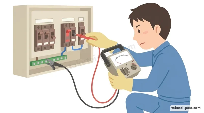
絶縁抵抗を測定する際は、まず分岐開閉器(ブレーカ)を切って無電圧状態にします。「電線と大地間(対地間)」を測定するときは、負荷(照明や機器)をつないだまま、点滅器(スイッチ)を「入(ON)」にして、回路全体を一括して測定できます(接地線にE端子[アース側]、電線にL端子[ライン側]をつなぎます)。
When measuring insulation resistance, first open the branch circuit breaker to de-energize the circuit. When measuring between wires and earth (wire-to-ground), you can leave loads (lights and appliances) connected and turn switches ON to measure the entire circuit at once (connect the E terminal to the grounding wire and the L terminal to the circuit conductors).
一方、「電線相互間(線間)」の絶縁抵抗を測定するときは、負荷がつながっていると負荷内部を通じて導通(0MΩ)してしまうため、必ずすべての負荷(電球やコンセントの機器)を取り外し、スイッチを「入(ON)」にして測定します。
Conversely, when measuring insulation resistance between wires (wire-to-wire), leaving loads connected would cause continuity (0MΩ) through the internal circuitry of the loads; therefore, you must disconnect all loads (remove bulbs and unplug appliances) and turn switches ON before measuring.
Key points
- 絶縁抵抗の最小値:対地150V以下=0.1MΩ以上、300V以下(対地150V超)=0.2MΩ以上、300V超=0.4MΩ以上
Minimum insulation resistance: <= 150V to ground = 0.1MΩ or more; <= 300V (> 150V to ground) = 0.2MΩ or more; > 300V = 0.4MΩ or more - 単相3線式100/200Vは対地電圧100Vなので「0.1MΩ以上」、三相3線式200Vは「0.2MΩ以上」
Single-phase 3-wire 100/200V has 100V to ground so it requires 0.1MΩ or more; three-phase 3-wire 200V requires 0.2MΩ or more - 電線と大地間(対地間)の測定では、負荷を接続したままスイッチを「入(ON)」にして測る
For wire-to-ground measurements, leave loads connected and turn switches ON - 電線相互間(線間)の測定では、すべての負荷を取り外しスイッチを「入(ON)」にして測る
For wire-to-wire measurements, disconnect all loads and turn switches ON
| Word | Meaning |
|---|---|
| 絶縁抵抗計 | insulation resistance tester |
| メガー | Megger (insulation tester) |
| 対地間 | between wire and earth (wire-to-ground) |
| 電線相互間 | between wires (wire-to-wire) |
接地抵抗計(アーステスタ)による接地抵抗の測定
Ground Resistance Measurement Using an Earth Tester
D種接地工事などで埋設した接地極と大地との間の接地抵抗値(100Ω以下など)を測定するには、「接地抵抗計(アーステスタ)」を使用します(回路計[テスタ]や絶縁抵抗計[メガー]では接地抵抗を測定できません)。
To measure the ground resistance value (such as 100Ω or less) between a buried grounding electrode (e.g., for Class D grounding) and the earth, a ground resistance tester (earth tester) is used (neither a multimeter nor an insulation resistance tester can measure ground resistance).
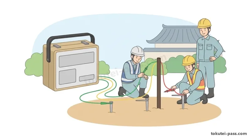
接地抵抗計には「E(被測定接地極)」「P(補助接地極・電位極)」「C(補助接地極・電流極)」の3つの端子があります。測定するときは、地面において「E極→P極→C極」の順に一直線上に並べ、それぞれ「約10m(5〜10m程度)」の間隔を離して補助接地棒を地面に打ち込みます。
An earth tester has three terminals: E (grounding electrode under test), P (auxiliary potential electrode), and C (auxiliary current electrode). When measuring, drive the auxiliary grounding spikes into the soil in a straight line in the order E → P → C, spaced approximately 10m (5 to 10m) apart from one another.
端子とリード線の色の対応は、一般的にE端子が「緑色」、P端子が「黄色」、C端子が「赤色」です。必ず測定対象の接地極Eのすぐ隣(真ん中)にP極を配置し、一番外側(約20m先)にC極を配置します。「内から順にE・P・C」と覚えましょう。
The standard lead wire colors corresponding to the terminals are green for the E terminal, yellow for the P terminal, and red for the C terminal. Always place the P electrode immediately next to the E electrode (in the middle) and the C electrode farthest away (about 20m from E). Memorize the order from the inside out as E - P - C.
測定の正しい手順は次のとおりです。①電池電圧が正常か確認する(バッテリーチェック)、②E・P・Cを接続し、「地電圧(地面に流れている漏れ電流などによる電圧)」が許容値(約10V)以下であることを確認する、③大きい抵抗レンジ(1000Ωなど)から小さいレンジへ切り換えて測定ボタンを押し、接地抵抗値を読み取ります。
The proper measurement procedure is as follows: ① Check that the battery voltage is normal (battery check); ② Connect the E, P, and C leads and verify that the earth voltage (stray voltage in the ground caused by leakage currents, etc.) is below the allowable limit (approx. 10V or less); ③ Switch from a higher resistance range (such as 1000Ω) down to an appropriate range, press the measure button, and read the ground resistance value.
Key points
- 接地抵抗の測定には「接地抵抗計(アーステスタ)」を使用する
Use a ground resistance tester (earth tester) to measure ground resistance - 被測定接地極(E)から一直線上に約10m間隔で「E→P→C」の順に配置する
Place the electrodes in a straight line from the electrode under test (E) at roughly 10m intervals in the order E → P → C - Eは緑、真ん中のP(電位極)は黄、一番遠いC(電流極)は赤のリード線をつなぐ
Connect the green lead to E, the yellow lead to the middle electrode P (potential), and the red lead to the farthest electrode C (current) - 測定手順は「電池確認→補助極の配置・接続→地電圧の確認→接地抵抗の測定」の順に行う
Measurement procedure: Battery check → Place & connect auxiliary spikes → Check earth voltage → Measure ground resistance
| Word | Meaning |
|---|---|
| 接地抵抗計 | ground resistance tester (earth tester) |
| 補助接地極 | auxiliary grounding electrode (P and C spikes) |
| 一直線上 | in a straight line |
| 地電圧 | earth voltage (stray ground potential) |
クランプ形漏れ電流計による絶縁状態の確認
Checking Insulation Condition with a Clamp-Type Leakage Current Meter
使用中のビルや工場、病院などで「停電させることができない(使用状態のまま)」電路の絶縁状態を確認したい場合は、メガーの代わりに「クランプ形漏れ電流計(リーククランプメータ)」を使用して漏れ電流(漏洩電流)を測定します。
When you need to verify the insulation condition of an energized circuit in an operating building, factory, or hospital where power cannot be shut off, use a clamp-type leakage current meter (leak clamp meter) instead of a Megger to measure the leakage current.
電気設備技術基準では、停電が困難な場合に漏れ電流を測定し、その値が「1mA以下」であれば、規定の絶縁抵抗値(0.1MΩ〜0.4MΩ以上)を満たしているもの(合格)とみなすことができます。
Under the Technical Standards for Electrical Equipment, when de-energizing a circuit is impractical, measuring a leakage current of 1mA or less is deemed equivalent to meeting the required insulation resistance values (0.1MΩ to 0.4MΩ or more) and passes inspection.
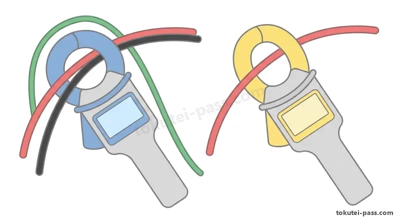
クランプ形漏れ電流計で電線をはさむ(クランプする)方法は、試験で図として頻出します。漏れ電流を測るときは、必ず「同一回路のすべての電線を一括して(単相2線式なら2本とも、単相3線式や三相3線式なら3本ともまとめて)」クランプするか、または「接地線(アース線)1本のみ」をクランプします。
How to clamp the wires with a clamp-type leakage current meter is frequently tested via diagrams on the exam. To measure leakage current, you must either clamp all conductors of the same circuit together at once (both wires in single-phase 2-wire, or all three wires together in single-phase 3-wire or three-phase 3-wire) or clamp only the single grounding wire.
もし、単相2線式のうち1本だけ、あるいは三相3線式のうち1本または2本だけをはさむと、漏れ電流ではなく通常の「負荷電流」が測定されてしまいます(逆に、通常の負荷電流をクランプ形電流計で測りたいときは、必ず電線を「1本だけ」はさみます)。
If you clamp only one wire of a single-phase 2-wire circuit, or only one or two wires of a three-phase 3-wire circuit, the meter will measure the normal load current rather than the leakage current (conversely, when you want to measure normal load current with a clamp ammeter, always clamp only a single wire).
Key points
- 停電できない使用中の電路では、「クランプ形漏れ電流計」で絶縁状態を確認する
For live circuits where power cannot be shut off, check insulation condition using a clamp-type leakage current meter - 漏れ電流が「1mA以下」であれば絶縁性能は合格とみなされる
A leakage current of 1mA or less is deemed to pass insulation performance requirements - 漏れ電流を測るときは「全電線(2本または3本)を一括」するか「接地線1本」をはさむ
To measure leakage current, clamp all circuit wires together (2 or 3 wires) or clamp a single grounding wire - 通常の負荷電流を測るときは、電線を「1本だけ」はさむ(複数本はさむと測れない)
To measure normal load current, clamp only a single wire (clamping multiple wires together will cancel out load current)
| Word | Meaning |
|---|---|
| クランプ形漏れ電流計 | clamp-type leakage current meter |
| 漏洩電流 | leakage current |
| 一括 | all together (clamped as a bundle) |
| 負荷電流 | load current |
電圧計・電流計・電力計の接続と各種測定器の用途
Connecting Voltmeters, Ammeters, and Wattmeters, and Uses of Measuring Instruments
回路の電圧・電流・電力を測定する際の計器の接続方法は基本でありながら頻出です。「電圧計(V)」は内部抵抗が非常に大きいため、負荷に対して必ず「並列」に接続します。「電流計(A)」は内部抵抗が非常に小さいため、負荷に対して必ず「直列」に接続します(電流計を誤って並列につなぐと短絡して焼損します)。
How to connect meters to measure circuit voltage, current, and power is fundamental and frequently tested. Because a voltmeter (V) has a very high internal resistance, it must always be connected in parallel with the load. Because an ammeter (A) has a very low internal resistance, it must always be connected in series with the load (accidentally connecting an ammeter in parallel causes a short circuit and burns out the meter).
単相交流の有効電力を測る「電力計(W)」には、内部に「電流コイル」と「電圧コイル」の2つが入っています。電流コイルは負荷と「直列」に、電圧コイルは負荷と「並列」に接続します。なお、電流計の測定範囲を広げるには並列に「分流器」や「変流器(CT)」を用い、電圧計には直列に「倍率器」や「計器用変圧器(VT)」を用います。
A wattmeter (W) used to measure single-phase AC active power contains two internal coils: a current coil and a voltage (potential) coil. The current coil is connected in series with the load, while the voltage coil is connected in parallel with the load. Note that to extend the measuring range of an ammeter, a shunt resistor or current transformer (CT) is used in parallel; for a voltmeter, a multiplier resistor or voltage transformer (VT) is used in series.
その他の専門測定器の用途も確実に区別しましょう。①「検相器(相順計)」:三相交流電源の「相順(R・S・Tの回転方向)」を調べる計器(電動機の逆回転防止に使う)。②「検電器(ネオン検電器・低圧検電器)」:電線に「電圧が来ているか(充電の有無)」や非接地側(黒線)を調べる器具。
Be sure to distinguish the purposes of other specialized instruments: ① Phase rotation meter (phase detector): checks the phase sequence (direction of rotation R - S - T) of a three-phase AC power supply (used to prevent reverse rotation of motors). ② Voltage detector (neon tester / low-voltage detector): checks whether a wire is live (energized) and identifies the ungrounded (black) conductor.
③「回転計(タコメータ/ストロボスコープ)」:電動機(モータ)などの1分間あたりの「回転速度(min⁻¹)」を測定する計器。④「照度計(ルクス計)」:作業面の「明るさ(照度:単位 lx[ルクス])」を測定する計器。⑤「力率計」:交流回路の力率(cosφ)を測定する計器です。
③ Tachometer (or stroboscope): measures the rotational speed per minute (min⁻¹) of electric motors. ④ Illuminance meter (lux meter): measures the brightness (illuminance, in units of lx - lux) on a work surface. ⑤ Power factor meter: measures the power factor (cosφ) of an AC circuit.
Key points
- 電流計は負荷に「直列」、電圧計は負荷に「並列」に接続する
Connect an ammeter in series with the load, and connect a voltmeter in parallel with the load - 電力計は電流コイルを負荷と「直列」、電圧コイルを負荷と「並列」に接続する
In a wattmeter, connect the current coil in series with the load and the voltage coil in parallel with the load - 検相器は三相交流の「相順(回転方向)」を調べ、検電器は「充電の有無」を調べる
A phase rotation meter (検相器) checks three-phase sequence; a voltage detector (検電器) checks whether a line is live - 回転計はモータの「回転速度(min⁻¹)」、照度計は床面などの「明るさ(lx)」を測定する
A tachometer (回転計) measures motor rotational speed (min⁻¹); a lux meter (照度計) measures brightness (lx)
| Word | Meaning |
|---|---|
| 電力計 | wattmeter (power meter) |
| 検相器 | phase rotation meter (phase sequence indicator) |
| 検電器 | voltage detector (live-line tester) |
| 照度計 | illuminance meter (lux meter) |
| 回転計 | tachometer (rotational speed meter) |
指示電気計器のJIS記号と電力量計の結線
JIS Symbols for Indicating Meters and Watt-Hour Meter (WHM) Wiring
アナログ指示電気計器の文字板(スケール板)には、動作原理や使用回路、置き方を示すJIS記号が記されています。①「可動コイル形(永久磁石の馬蹄形マーク)」:直流(―)専用で、目盛が均等で感度が高い計器です(整流器[ダイオードマーク]を組み合わせた「整流形」は交流用で、テスタの交流電圧測定などに使われます)。
The dial face of analog indicating electrical meters displays JIS symbols indicating their operating principle, current type, and mounting position. ① Moving-coil type (horseshoe permanent magnet symbol): for DC (―) only, featuring a uniform scale and high sensitivity (when combined with a diode rectifier symbol, it becomes a rectifier type used for AC, such as AC voltage measurement in multimeters).
②「可動鉄片形」:交流・直流の両方(交直両用)に使えますが、主に商用周波数の「交流(〜)電流計・電圧計」として盤面に最も多く使われています。③「電流力計形」:交直両用で、主に「電力計」として使われます。④「誘導形」:交流(〜)専用で、「電力量計(WHM)」に使われます。
② Moving-iron type: usable for both AC and DC, and most widely used on switchboards as commercial-frequency AC (〜) ammeters and voltmeters. ③ Electrodynamometer type: usable for both AC and DC, primarily used as wattmeters. ④ Induction type: for AC (〜) only, used for watt-hour meters (WHM).
計器の置き方の記号は、「⊥」が鉛直(垂直に立てて使う)、「─」が水平(平らに寝かせて使う)、「∠60°」が傾斜(60度傾けて使う)を表します。また、目盛板の「2.5」などの数字は階級(許容誤差が最大目盛値の±2.5%以内)を表します。
Symbols for meter mounting orientation are: ⊥ for vertical mounting (standing upright), ─ for horizontal mounting (lying flat), and ∠60° for inclined mounting (tilted at 60 degrees). Additionally, a number such as 2.5 on the scale plate indicates the accuracy class (allowable error within ±2.5% of the full-scale value).
家庭や店舗の使用電力量(kWh)を積算する「電力量計(WHM)」の結線も重要です。単相2線式では左から「1S(電源黒)・2S(電源白=接地側)・2L(負荷白)・1L(負荷黒)」の順、単相3線式では真ん中の端子(2S・2L)に必ず「中性線(白線)」を接続します。
Terminal wiring for a watt-hour meter (integrating wattmeter: WHM), which records energy consumption (kWh) in homes and shops, is also important. In a single-phase 2-wire system, terminals are wired from left to right as 1S (source black), 2S (source white = grounded), 2L (load white), and 1L (load black); in a single-phase 3-wire system, the neutral wire (white grounded wire) must always be connected to the center terminals (2S and 2L).
Key points
- 可動コイル形は「直流専用」、可動鉄片形と電流力計形は「交直両用」
Moving-coil type is for DC only; moving-iron and electrodynamometer types work on both AC and DC - 誘導形は「交流専用」であり、電力量計(積算電力計)に使用される
Induction type is for AC only and is used in watt-hour meters (WHM) - 計器の置き方記号:「⊥」は鉛直(垂直)、「─」は水平置きを表す
Meter orientation symbols: ⊥ indicates vertical mounting, and ─ indicates horizontal mounting - 単相3線式の電力量計では、真ん中の端子(2S・2L)に中性線(接地側白線)をつなぐ
In a single-phase 3-wire watt-hour meter, the neutral wire (grounded white wire) must connect to the center terminals (2S and 2L)
| Word | Meaning |
|---|---|
| 可動コイル形 | moving-coil type (for DC) |
| 可動鉄片形 | moving-iron type (for AC and DC) |
| 誘導形 | induction type (for AC - watt-hour meters) |
| 電力量計 | watt-hour meter (electricity meter / WHM) |
試験によく出るポイントと覚え方
Frequent Exam Points and Memory Tricks
絶縁抵抗の最小値(0.1MΩ・0.2MΩ・0.4MΩ)は必ず出る得点源です。「単相100Vと単相3線式100/200Vは対地100V(150V以下)だから『0.1MΩ以上』」「三相200Vは対地200V(150V超)だから『0.2MΩ以上』」「300V超は『0.4MΩ以上』」と丸暗記しましょう。
The minimum insulation resistance values (0.1MΩ, 0.2MΩ, 0.4MΩ) appear on every single exam. Memorize them as pairs: Both single-phase 100V and single-phase 3-wire 100/200V have a voltage to ground of 100V (150V or less), so both require 0.1MΩ or more; Three-phase 200V has a voltage to ground of 200V (over 150V), so it requires 0.2MΩ or more; 400V-class circuits (over 300V) require 0.4MΩ or more.
メガー測定の条件は、「対地間(大地との間)は負荷をつないだままスイッチON」「線間(電線どうし)は負荷を全部外してスイッチON」です。「電球がつながったままだと、黒線と白線が電球の中でつながってショート状態に見えてしまうから線間では外す」と理由を理解すれば絶対に間違えません。
For Megger testing conditions: Wire-to-ground is measured with loads connected and switches ON; Wire-to-wire is measured with all loads disconnected and switches ON. Once you understand why—if a lightbulb remains connected, the black and white wires are connected through the filament and look like a short circuit during a wire-to-wire test—you will never mix them up.
アーステスタの端子配置は「E(緑)・P(黄)・C(赤)を一直線に10m間隔」、クランプ形漏れ電流計は「全部まとめてはさめば漏れ電流(1mA以下で合格)、1本だけはさめば負荷電流」と整理しておきましょう。
For the earth tester, remember: E (green) - P (yellow) - C (red) in a straight line 10m apart. For clamp meters: Clamp all wires together to measure leakage current (1mA or less passes), and clamp just 1 wire to measure load current.
Key points
- 絶縁抵抗:単相100V・単相3線式100/200V=0.1MΩ以上、三相200V=0.2MΩ以上、300V超=0.4MΩ以上
Insulation resistance: 1-phase 100V & 1-phase 3-wire 100/200V >= 0.1MΩ; 3-phase 200V >= 0.2MΩ; over 300V >= 0.4MΩ - メガー測定:スイッチは常にON。対地間は「負荷あり」で可、電線相互間は「全負荷を外す」
Megger testing: switches always ON. Leave loads connected for wire-to-ground; disconnect all loads for wire-to-wire - 接地抵抗計:一直線上に約10m間隔で「E(被測定極)→P(電位極)→C(電流極)」の順に配置
Earth tester: place in a straight line ~10m apart in the order E (test electrode) → P (potential) → C (current) - クランプ形漏れ電流計:全電線一括(または接地線1本)をはさみ、「1mA以下」なら合格
Clamp leakage meter: clamp all wires together (or 1 grounding wire); 1mA or less passes inspection - 計器の接続と原理:電流計=直列、電圧計=並列。可動コイル=直流、可動鉄片=交直、誘導形=交流(WHM)
Meters: Ammeter = series, Voltmeter = parallel. Moving-coil = DC, Moving-iron = AC/DC, Induction = AC (WHM)
| Word | Meaning |
|---|---|
| 絶縁抵抗最小値 | minimum insulation resistance value |
| 一括クランプ | bundle clamping (clamping all wires together) |
| 相順 | phase sequence (phase rotation) |
Inspection & Measurement
Practice this chapter in the appOfficial references
- 経済産業省「電気設備に関する技術基準を定める省令(第58条 低圧の電路の絶縁性能)」 — https://www.meti.go.jp/policy/safety_security/industrial_safety/sangyo/electric/
- 日本産業規格「JIS C 1302 絶縁抵抗計」「JIS C 1304 接地抵抗計」「JIS C 1102 指示電気計器」 — https://www.jisc.go.jp/