
Basic Electrical Theory
電気に関する基礎理論
Class 2 Electrician 第二種電気工事士 (written exam) · 第二種電気工事士(学科試験) · Written by Tokutei Pass based on the official study texts; not copied verbatim.
オームの法則と直流直並列回路・分圧と分流
Ohm's Law, DC Series-Parallel Circuits, Voltage Division and Current Division
第二種電気工事士の学科試験では、問題1の問1から問5までが電気基礎理論の計算問題です。電卓は使用禁止ですが、基本公式と整数比のパターンを押さえれば確実に得点源にできます。
In the Second-Class Electrician written exam, Questions 1 through 5 of Part 1 are calculation problems on basic electrical theory. Calculators are prohibited, but mastering the fundamental formulas and standard integer ratios makes these questions a reliable source of points.
抵抗R(Ω)に電圧V(V)を加えたときに流れる電流I(A)は「I=V÷R」、電圧は「V=I×R」、抵抗は「R=V÷I」で表されます。これをオームの法則と呼び、すべての回路計算の出発点となります。
When a voltage V (V) is applied across a resistor R (Ω), the resulting current I (A) is expressed as "I = V ÷ R", voltage as "V = I × R", and resistance as "R = V ÷ I". This is known as Ohm's Law and serves as the starting point for all circuit calculations.
複数の抵抗を一本道につなぐ直列接続では、どの抵抗にも同じ電流Iが流れ、合成抵抗は単純な足し算「R=R1+R2」になります。電源電圧Vは抵抗値の比に比例して各抵抗に分圧されます。
In a series connection where multiple resistors are joined along a single path, the same current I flows through every resistor, and the combined resistance is a simple sum: "R = R1 + R2". The source voltage V is divided across each resistor in direct proportion to its resistance value.
一方、抵抗を枝分かれにつなぐ並列接続では、各枝にかかる電圧Vが等しくなります。2個の抵抗の並列合成抵抗は「和分の積:R=(R1×R2)÷(R1+R2)」で素早く計算できます。
Conversely, in a parallel connection where resistors branch out, the voltage V across each branch is equal. The combined resistance of two resistors in parallel can be quickly calculated using the "product over sum" rule: "R = (R1 × R2) ÷ (R1 + R2)".
特に「同じ抵抗値Rをn個並列につなぐと合成抵抗はR÷nになる」という性質は頻出です。また並列回路の電流は抵抗値の逆比に分流し、抵抗が小さい枝ほど大きな電流が流れます。
In particular, the rule that "connecting n identical resistors of value R in parallel gives a combined resistance of R ÷ n" is tested very frequently. Also, current in a parallel circuit divides in inverse proportion to branch resistance, so a larger current flows through the branch with smaller resistance.
Key points
- オームの法則は「V=I×R」「I=V÷R」「R=V÷I」の3つの形で自在に変換する。
Freely convert among the three forms of Ohm's Law: "V = I × R", "I = V ÷ R", and "R = V ÷ I". - 直列接続は電流が一定で合成抵抗は「R1+R2」、電圧は抵抗の比に比例して分圧される。
In series circuits, current is constant, combined resistance is "R1 + R2", and voltage divides proportionally to resistance. - 2個の並列合成抵抗は「(R1×R2)÷(R1+R2)」で求め、同じ抵抗Rがn個並列なら「R÷n」になる。
For two parallel resistors, use "(R1 × R2) ÷ (R1 + R2)"; for n identical resistors R in parallel, the combined resistance is "R ÷ n". - 【例】抵抗 R1 = 8Ωと R2 = 12Ωの直列回路に 100Vを加える → 合成抵抗 R = 8 + 12 = 20Ω、電流 I = 100 ÷ 20 = 5A、R1の電圧 V1 = 5 × 8 = 40V
Example: A series circuit of R1 = 8Ω and R2 = 12Ω connected to 100V → Combined resistance R = 8 + 12 = 20Ω, current I = 100 ÷ 20 = 5A, voltage across R1 is V1 = 5 × 8 = 40V - 【例】抵抗 20Ωと 30Ωの並列回路に全電流 10Aが流れる → 合成抵抗 R =(20 × 30)÷(20 + 30)= 12Ω、20Ω側の電流 I1 = 10 × 30 ÷(20 + 30)= 6A
Example: A parallel circuit of 20Ω and 30Ω carrying 10A total current → Combined resistance R = (20 × 30) ÷ (20 + 30) = 12Ω, current through the 20Ω branch is I1 = 10 × 30 ÷ (20 + 30) = 6A
| Word | Meaning |
|---|---|
| オームの法則 | Ohm's Law |
| 直列接続と並列接続 | series connection and parallel connection |
| 合成抵抗 | combined resistance (equivalent resistance) |
| 分圧と分流 | voltage division and current division |
キルヒホッフの法則とホイートストンブリッジの平衡条件
Kirchhoff's Laws and Wheatstone Bridge Balance Condition
複雑な直流回路の電流や電圧を求めるときはキルヒホッフの法則を使います。第1法則(電流則)は「回路内のどの接続点でも、流れ込む電流の合計と流れ出る電流の合計は等しい」という決まりです。
Kirchhoff's Laws are used to find currents and voltages in complex DC circuits. The First Law (Current Law) states that "at any node (junction) in a circuit, the sum of currents flowing in equals the sum of currents flowing out."
第2法則(電圧則)は「閉じた回路(ループ)を一周するとき、電源の起電力の和と各抵抗での電圧降下(I×R)の和は等しい」という決まりです。問1の直並列回路でもこの2つの法則が活躍します。
The Second Law (Voltage Law) states that "around any closed loop in a circuit, the sum of source electromotive forces equals the sum of voltage drops (I × R) across each resistor." Both laws are essential for solving the series-parallel networks in Question 1.
また未知の抵抗値を正確に測る「ホイートストンブリッジ回路」も定番問題です。ひし形に配置した4つの抵抗R1・R2・R3・R4の中央に検流計Gをつないだ回路です。
Another classic exam topic is the "Wheatstone bridge circuit" used to accurately measure an unknown resistance. It consists of four resistors R1, R2, R3, and R4 arranged in a diamond with a sensitive galvanometer G connected across the center.
中央の検流計Gに電流が全く流れない(0Aになる)状態を「平衡状態」といい、このとき向かい合う辺(対辺)の抵抗を掛け合わせた積が等しくなる「R1×R4=R2×R3」が成り立ちます。
The state in which no current flows through the center galvanometer G (0 A) is called the "balanced state." When balanced, the products of the resistances on opposite sides are equal: "R1 × R4 = R2 × R3".
ブリッジが平衡状態にあるときは中央の検流計Gの枝に電流が流れないため、回路全体の合成抵抗を計算する際には中央の検流計を取り除き、単なる上下2本の並列回路として計算します。
When the bridge is balanced, zero current flows through the center galvanometer branch. Therefore, when calculating the total combined resistance of the entire circuit, you simply remove the center galvanometer G and calculate it as two series branches connected in parallel.
Key points
- キルヒホッフ第1法則:接続点に流入する電流の和と流出する電流の和は等しい。
Kirchhoff's First Law: The sum of currents entering a junction equals the sum of currents leaving it. - ホイートストンブリッジの平衡条件(検流計Gの電流が0A):対辺の積「R1×R4=R2×R3」が等しい。
Wheatstone bridge balance condition (galvanometer G current is 0 A): Products of opposite arms are equal, "R1 × R4 = R2 × R3". - 平衡時のブリッジ全体の合成抵抗は、検流計Gの線を無視して直並列計算を行う。
To find total bridge resistance when balanced, ignore the center galvanometer G wire and compute as a series-parallel circuit. - 【例】ホイートストンブリッジで R1 = 4Ω、R2 = 8Ω、R3 = 6Ω が平衡しているとき → R4 = 8 × 6 ÷ 4 = 12Ω、上枝(4 + 6 = 10Ω)と下枝(8 + 12 = 20Ω)の全体合成抵抗 R =(10 × 20)÷(10 + 20)= 約 6.7Ω
Example: In a balanced Wheatstone bridge with R1 = 4Ω, R2 = 8Ω, R3 = 6Ω → R4 = 8 × 6 ÷ 4 = 12Ω; total resistance of upper branch (4 + 6 = 10Ω) and lower branch (8 + 12 = 20Ω) is R = (10 × 20) ÷ (10 + 20) ≈ 6.7Ω - 【例】接続点に 9Aが流入し一方へ 4Aが流出 → もう一方の電流 I = 9 − 4 = 5A(電源 30Vの閉回路で抵抗 2Ωに 9Aが流れるとき、残りの抵抗の電圧降下 V = 30 − 2 × 9 = 12V)
Example: If 9A enters a junction and 4A leaves through one branch → Current in the other branch is I = 9 − 4 = 5A (in a 30V closed loop where 9A flows through a 2Ω resistor, voltage drop across the remaining resistor is V = 30 − 2 × 9 = 12V)
| Word | Meaning |
|---|---|
| キルヒホッフの法則 | Kirchhoff's Laws |
| ホイートストンブリッジ回路 | Wheatstone bridge circuit |
| 検流計 | galvanometer |
| 平衡状態 | balanced state |
導体の電気抵抗(長さ・断面積・直径の関係)と温度変化
Conductor Resistance (Length, Cross-Section, Diameter) and Temperature Effect
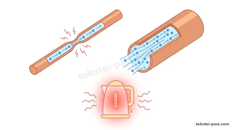
問2で毎回出題されるのが、銅線などの電線(導体)の電気抵抗Rを求める計算です。導体の抵抗R(Ω)は材料固有の「抵抗率ρ(ロー)」と「長さL(m)」に比例し、「断面積A(mm²)」に反比例します(R=ρ×L÷A)。
Question 2 regularly tests the calculation of electrical resistance R of a conductor such as a copper wire. Conductor resistance R (Ω) is directly proportional to the material's "resistivity ρ (rho)" and "length L (m)", and inversely proportional to its "cross-sectional area A (mm²)" (R = ρ × L ÷ A).
単線(丸い1本の導体)の太さが「直径D(mm)」で与えられた場合、円の断面積は「A=π×D²÷4」なので、抵抗の公式は「R=(4×ρ×L)÷(π×D²)」となります。
When the thickness of a solid round wire is given as "diameter D (mm)", since the area of a circle is "A = π × D² ÷ 4", the resistance formula becomes "R = (4 × ρ × L) ÷ (π × D²)".
ここで最も重要な鉄則は、「電線の抵抗Rは長さLに比例し、直径Dの2乗(D²)に反比例する」という点です。直径Dが2倍になると断面積は4倍になるため、同じ長さなら抵抗は「4分の1(1/4)」に減ります。
The most important ironclad rule here is that "wire resistance R is proportional to length L and inversely proportional to the square of diameter D (D²)." Doubling the diameter D quadruples the cross-sectional area, so for the same length, resistance drops to "one-fourth (1/4)".
したがって、直径d・長さlの銅線と「全く同じ抵抗値」になる銅線を選ぶ問題では、「長さ÷直径の2乗」の比が同じものを探します。直径が2倍(2d)なら長さを4倍(4l)にしたとき抵抗が等しくなります。
Therefore, in problems asking which copper wire has the "exact same resistance" as a wire of diameter d and length l, look for the option with the same ratio of "length ÷ diameter squared." If the diameter is doubled (2d), the length must be quadrupled (4l) to keep resistance equal.
なお、銅やアルミニウムなどの金属導体は、温度が上がると電気抵抗が少しずつ増える性質(正の抵抗温度係数)を持っています。電線の導電率は軟銅を基準(約100%)として表されます。
Note that metallic conductors such as copper and aluminum have a property where electrical resistance increases slightly as temperature rises (positive temperature coefficient of resistance). Electrical conductivity of wires is expressed as a percentage relative to standard annealed copper (approx. 100%).
Key points
- 断面積A(mm²)で表す電線抵抗は「R=ρ×L÷A」で、長さLに比例し断面積Aに反比例する。
Wire resistance in terms of cross-sectional area A (mm²) is "R = ρ × L ÷ A", proportional to length L and inversely proportional to area A. - 直径D(mm)で表す電線抵抗は「R=(4×ρ×L)÷(π×D²)」で、直径Dの2乗に反比例する。
Wire resistance in terms of diameter D (mm) is "R = (4 × ρ × L) ÷ (π × D²)", inversely proportional to diameter squared D². - 直径が2倍になると断面積は4倍・抵抗は1/4になるため、長さを4倍にすると元の抵抗と等しくなる。
Doubling diameter quadruples area and cuts resistance to 1/4, so quadrupling length restores the original resistance. - 【例】断面積 A = 5.5mm²、長さ L = 110m の銅線(抵抗率 ρ = 0.0172Ω・mm²/m) → 電線抵抗 R = 0.0172 × 110 ÷ 5.5 = 0.344Ω
Example: A copper wire with area A = 5.5mm² and length L = 110m (resistivity ρ = 0.0172 Ω·mm²/m) → Wire resistance R = 0.0172 × 110 ÷ 5.5 = 0.344Ω - 【例】抵抗 1.2Ωの電線と同材質で、直径を 2倍・長さを 2倍にした電線 → 断面積は 2 × 2 = 4倍になるため、抵抗 R = 1.2 × 2 ÷ 4 = 0.6Ω
Example: A wire of the same material as a 1.2Ω wire with 2 times the diameter and 2 times the length → Since area increases by 2 × 2 = 4 times, resistance R = 1.2 × 2 ÷ 4 = 0.6Ω
| Word | Meaning |
|---|---|
| 抵抗率(ρ) | resistivity (ρ) |
| 断面積(mm²)と直径(mm) | cross-sectional area (mm²) and diameter (mm) |
| 導電率 | electrical conductivity |
| 抵抗温度係数 | temperature coefficient of resistance |
電力・電力量とジュールの法則・水の加熱計算
Electric Power, Electric Energy, Joule's Law and Water Heating Calculations
問3では電流による発熱量や電力量の計算が出題されます。1秒間あたりに消費される電気の仕事率を「電力P(単位:W)」といい、「P=V×I=I²×R=V²÷R」の3つの式で計算します。
Question 3 tests calculations of heat generation and electric energy from current. The rate of electrical work consumed per second is "electric power P (unit: W)", calculated using three formulas: "P = V × I = I² × R = V² ÷ R".
電力P(W)に使用時間t(h:時間)を掛けたものを「電力量W(単位:WhまたはkWh)」といいます。一方、電力P(W)に「秒数t(s:秒)」を掛けたものが発熱量(ジュール熱)Q(単位:J)であり、「Q=P×t=I²×R×t(J)」となります。
Multiplying power P (W) by usage time t (h: hours) gives "electric energy W (unit: Wh or kWh)". Meanwhile, multiplying power P (W) by "time in seconds t (s: seconds)" gives the generated heat (Joule heat) Q (unit: J): "Q = P × t = I² × R × t (J)".
時間の単位換算が最大のポイントで、1時間は「60分=3,600秒」です。したがって「1Wh=3,600W・s=3,600J=3.6kJ」となり、「1kWh=3,600kJ」という換算値を暗記しておくと計算が一気に速くなります。
Time unit conversion is the key point: 1 hour equals "60 minutes = 3,600 seconds." Thus "1 Wh = 3,600 W·s = 3,600 J = 3.6 kJ", and memorizing the conversion "1 kWh = 3,600 kJ" speeds up your calculations dramatically.
電気湯沸器で質量m(kg:水1Lは1kg)の水の温度をΔt(℃またはK)だけ上昇させるのに必要な熱量Q(kJ)は、水の比熱「c=4.2kJ/(kg・K)」を用いて「Q=4.2×m×Δt(kJ)」で求めます。
When an electric water heater raises the temperature of a mass m (kg; 1 L of water is 1 kg) of water by Δt (°C or K), the required heat Q (kJ) is found using the specific heat of water "c = 4.2 kJ/(kg·K)" via the formula "Q = 4.2 × m × Δt (kJ)".
熱効率が100%(熱損失を無視)なら「ヒーターの発熱量P×t=水が得る熱量4.2×m×Δt」として加熱時間や電力量を逆算します。熱効率(イータ)が与えられた場合は、ヒーターの発熱量にを掛けた分だけが水の加熱に使われます。
If thermal efficiency is 100% (ignoring heat loss), set "heater output heat P × t = heat absorbed by water 4.2 × m × Δt" to solve for heating time or electric energy. If a thermal efficiency (eta) is given, only the heater output multiplied by contributes to heating the water.
Key points
- 電力は「P=V×I=I²×R=V²÷R(W)」、発熱量は秒数を掛けた「Q=I²×R×t(J)」で求める。
Electric power is "P = V × I = I² × R = V² ÷ R (W)", and heat generated is found by multiplying by seconds: "Q = I² × R × t (J)". - 1時間=3,600秒であるため、「1Wh=3.6kJ」「1kWh=3,600kJ」の換算を必ず覚える。
Because 1 hour = 3,600 seconds, always memorize the conversions "1 Wh = 3.6 kJ" and "1 kWh = 3,600 kJ". - 水m(kg)をΔt(K)温める熱量は「Q=4.2×m×Δt(kJ)」であり、3,600で割れば電力量(kWh)になる。
Heat needed to warm m (kg) of water by Δt (K) is "Q = 4.2 × m × Δt (kJ)"; dividing by 3,600 converts it into electric energy (kWh). - 【例】電圧 100V・消費電力 1,500W の電熱器を 20分間(1,200秒)使用 → 発熱量 Q = 1,500 × 1,200 = 1,800,000J = 1,800kJ(電力量 W = 1,800 ÷ 3,600 = 0.5kWh)
Example: Using a 100V, 1,500W electric heater for 20 minutes (1,200 seconds) → Heat generated Q = 1,500 × 1,200 = 1,800,000J = 1,800kJ (electric energy W = 1,800 ÷ 3,600 = 0.5kWh) - 【例】水 30kg の温度を 20K(20℃)上昇させるのに必要な熱量と電力量(効率 100%) → Q = 4.2 × 30 × 20 = 2,520kJ、電力量 W = 2,520 ÷ 3,600 = 0.7kWh
Example: Heat and electric energy needed to raise 30kg of water by 20K (20℃, 100% efficiency) → Q = 4.2 × 30 × 20 = 2,520kJ, electric energy W = 2,520 ÷ 3,600 = 0.7kWh
| Word | Meaning |
|---|---|
| 電力(W)と電力量(Wh・kWh) | electric power (W) and electric energy (Wh, kWh) |
| ジュールの法則と発熱量(J・kJ) | Joule's Law and heat quantity (J, kJ) |
| 水の比熱(4.2kJ/kg・K) | specific heat of water (4.2 kJ/kg·K) |
| 熱効率 | thermal efficiency |
静電気・コンデンサの直並列接続と電磁気の基礎
Electrostatics, Series-Parallel Capacitors and Basics of Electromagnetism
2枚の金属板(極板)を向かい合わせて電荷を蓄える部品をコンデンサといい、電気を蓄える能力を「静電容量C(単位:FまたはμF)」と呼びます。蓄えられる電荷Q(C)は「Q=C×V」で表されます。
A component that stores electric charge between two facing metal plates (electrodes) is a capacitor, and its charge-storing capability is called "capacitance C (unit: F or μF)". The stored charge Q (C) is expressed as "Q = C × V".
平行平板コンデンサの静電容量Cは、極板の面積Sと間に挟む絶縁物の誘電率εに比例し、極板間の距離dに反比例します。面積が広く隙間が狭いほど多くの電気を蓄えられます。
The capacitance C of a parallel-plate capacitor is directly proportional to the plate area S and the permittivity ε of the insulating dielectric between the plates, and inversely proportional to the distance d between plates. Wider plates and a narrower gap store more charge.
コンデンサの合成静電容量の公式は「抵抗の直並列と逆」になります。並列接続では極板面積が増えるため単純な和「C=C1+C2」になり、直列接続では和分の積「C=(C1×C2)÷(C1+C2)」となります。
The formulas for combined capacitance are "opposite to those for series and parallel resistors." Parallel connection increases total plate area, giving a simple sum "C = C1 + C2", whereas series connection follows product over sum "C = (C1 × C2) ÷ (C1 + C2)".
また電磁気の分野では、磁束密度B(T)の磁界中に置かれた長さL(m)の電線に電流I(A)を流すと、フレミングの左手の法則の向きに電磁力「F=B×I×L(N)」が働きます(電動機が回る原理)。
In electromagnetism, when a current I (A) flows through a wire of length L (m) placed in a magnetic field of flux density B (T), an electromagnetic force "F = B × I × L (N)" acts in the direction given by Fleming's Left-Hand Rule (the principle behind electric motors).
逆にコイルを貫く磁束が時間的に変化すると、その変化を妨げる向き(レンツの法則)に誘導起電力が発生します。これをファラデーの電磁誘導の法則といい、発電機や変圧器の基本原理となっています。
Conversely, when the magnetic flux passing through a coil changes over time, an induced electromotive force is generated in a direction that opposes the change (Lenz's Law). This is Faraday's Law of Electromagnetic Induction, the fundamental principle of generators and transformers.
Key points
- コンデンサの電荷は「Q=C×V」であり、静電容量Cは極板面積に比例し極板間距離に反比例する。
Capacitor charge is "Q = C × V"; capacitance C is proportional to plate area and inversely proportional to plate separation. - コンデンサの合成容量は抵抗と逆で、並列接続が足し算「C1+C2」、2個直列が「(C1×C2)÷(C1+C2)」になる。
Combined capacitance is the reverse of resistance: parallel adds as "C1 + C2", and two in series use "(C1 × C2) ÷ (C1 + C2)". - 磁界中の電流が受ける電磁力は「F=B×I×L(N)」であり、左手の法則は電動機、右手の法則は発電機に対応する。
Electromagnetic force on a current in a magnetic field is "F = B × I × L (N)"; the Left-Hand Rule applies to motors and the Right-Hand Rule to generators. - 【例】静電容量 10μFと 40μFのコンデンサ → 並列合成容量は 10 + 40 = 50μF、直列合成容量は(10 × 40)÷(10 + 40)= 8μF(8μFに 100Vを加えると電荷 Q = 8 × 100 = 800μC)
Example: Two capacitors of 10μF and 40μF → Parallel capacitance is 10 + 40 = 50μF, series capacitance is (10 × 40) ÷ (10 + 40) = 8μF (applying 100V to 8μF gives charge Q = 8 × 100 = 800μC) - 【例】磁束密度 B = 0.4T の磁界中に長さ L = 0.5m の導体を直角に置き、電流 I = 15A を流す → 電磁力 F = 0.4 × 15 × 0.5 = 3N
Example: A conductor of length L = 0.5m placed perpendicular to a magnetic field of flux density B = 0.4T carrying current I = 15A → Electromagnetic force F = 0.4 × 15 × 0.5 = 3N
| Word | Meaning |
|---|---|
| 静電容量(F・μF) | capacitance (F, μF) |
| 誘電率 | permittivity (dielectric constant) |
| 電磁力(フレミングの左手の法則) | electromagnetic force (Fleming's Left-Hand Rule) |
| 電磁誘導の法則 | law of electromagnetic induction |
単相交流回路の基礎(実効値・最大値・周波数・リアクタンス)
Single-Phase AC Basics (RMS Value, Peak Value, Frequency, Reactance)
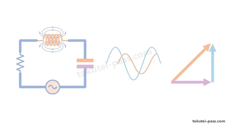
家庭や工場に送られる電気は、時間とともに向きと大きさが正弦波(サインカーブ)状に変化する交流(AC)です。交流100Vや200Vという普段の値は、直流と同じ仕事をする「実効値V」を表しています。
Electricity supplied to homes and factories is alternating current (AC), whose direction and magnitude vary sinusoidally over time. Everyday ratings such as 100 V AC or 200 V AC represent the "effective (RMS) value V" that performs the same work as an equivalent DC voltage.
正弦波交流の波の頂点である「最大値Vm」は実効値Vの「√2倍(約1.41倍)」です(Vm=√2×V)。たとえば実効値100Vの交流電圧の最大値は約141V、実効値200Vなら約283Vに達します。
The crest of a sine wave, called the "maximum (peak) value Vm", is "√2 times (approx. 1.41 times)" the effective value V (Vm = √2 × V). For example, an AC voltage with an effective value of 100 V reaches a peak of about 141 V, and 200 V RMS reaches about 283 V.
1秒間に波が繰り返す回数を「周波数f(単位:Hz)」といい、1回の波にかかる時間「周期T(秒)」とは「T=1÷f」の逆数関係にあります。日本の商用周波数は東日本が50Hz(T=0.02秒)、西日本が60Hzです。
The number of wave cycles per second is "frequency f (unit: Hz)", which is the reciprocal of the time for one cycle, "period T (seconds)", via "T = 1 ÷ f". Japan's commercial power frequency is 50 Hz (T = 0.02 s) in eastern Japan and 60 Hz in western Japan.
交流回路にコイル(インダクタンスL[H])をつなぐと、電流の変化を妨げる抵抗の働き「誘導性リアクタンスXL(Ω)」が生じます。式は「XL=2πfL」で、周波数fに比例して大きくなり、電流の位相は電圧より90度遅れます。
Connecting a coil (inductance L in H) to an AC circuit creates opposition to current change called "inductive reactance XL (Ω)". Its formula is "XL = 2πfL", increasing proportionally with frequency f, and the current phase lags behind the voltage by 90 degrees.
逆にコンデンサ(静電容量C[F])をつなぐと「容量性リアクタンスXC=1÷(2πfC)(Ω)」が生じます。XCは周波数fに反比例し、電流の位相は電圧より90度進みます。
Conversely, connecting a capacitor (capacitance C in F) creates "capacitive reactance XC = 1 ÷ (2πfC) (Ω)". XC is inversely proportional to frequency f, and the current phase leads the voltage by 90 degrees.
Key points
- 正弦波交流の最大値は「Vm=√2×実効値V」であり、実効値100Vの最大値は約141V、周期は「T=1÷f」である。
The peak value of a sine wave is "Vm = √2 × RMS value V" (approx. 141 V for 100 V RMS), and period is "T = 1 ÷ f". - コイルの誘導性リアクタンスは「XL=2πfL(Ω)」で周波数fに比例し、電流は電圧より90度遅れる。
A coil's inductive reactance is "XL = 2πfL (Ω)", proportional to frequency f, with current lagging voltage by 90 degrees. - コンデンサの容量性リアクタンスは「XC=1÷(2πfC)(Ω)」で周波数fに反比例し、電流は電圧より90度進む。
A capacitor's capacitive reactance is "XC = 1 ÷ (2πfC) (Ω)", inversely proportional to frequency f, with current leading voltage by 90 degrees. - 【例】実効値 200V・周波数 60Hzの交流電源 → 最大電圧 Vm = 1.41 × 200 = 282V、周期 T = 1 ÷ 60 = 約 0.0167秒(コイル L = 0.05H の誘導性リアクタンス XL = 2 × 3.14 × 60 × 0.05 = 18.84Ω)
Example: An AC supply of 200V RMS at 60Hz → Peak voltage Vm = 1.41 × 200 = 282V, period T = 1 ÷ 60 ≈ 0.0167 s (inductive reactance of coil L = 0.05H is XL = 2 × 3.14 × 60 × 0.05 = 18.84Ω) - 【例】周波数 50Hz・電圧 100Vの交流回路に静電容量 C = 0.0001F(100μF)を接続 → 容量性リアクタンス XC = 1 ÷(2 × 3.14 × 50 × 0.0001)= 約 31.8Ω、電流 IC = 100 ÷ 31.8 = 約 3.14A
Example: Connecting a capacitor C = 0.0001F (100μF) to a 50Hz, 100V AC circuit → Capacitive reactance XC = 1 ÷ (2 × 3.14 × 50 × 0.0001) ≈ 31.8Ω, current IC = 100 ÷ 31.8 ≈ 3.14A
| Word | Meaning |
|---|---|
| 実効値と最大値(Vm=√2V) | effective (RMS) value and peak value (Vm = √2V) |
| 周波数(Hz)と周期(T=1÷f) | frequency (Hz) and period (T = 1 ÷ f) |
| 誘導性リアクタンス(XL=2πfL) | inductive reactance (XL = 2πfL) |
| 容量性リアクタンス(XC) | capacitive reactance (XC) |
単相交流の直列・並列回路とインピーダンス・電力・力率
Single-Phase AC Series-Parallel Circuits, Impedance, Power and Power Factor
問4で必ず出題される単相交流回路では、抵抗RとリアクタンスX(コイルXLやコンデンサXC)の電流・電圧に90度の位相差があるため、単純な足し算ではなく「直角三角形(三平方の定理)」で合成します。
In single-phase AC circuits tested in Question 4, because there is a 90-degree phase difference between resistor R and reactance X (coil XL or capacitor XC), quantities cannot be added algebraically but must be combined using a "right triangle (Pythagorean theorem)."
RとXを「直列接続」した回路では、回路全体の電流に対する妨げ「インピーダンスZ(Ω)」は「Z=√(R²+X²)」となり、電流は「I=V÷Z」、力率は「cosφ=R÷Z」で求めます。
In a circuit with R and X in "series", the total opposition to current, called "impedance Z (Ω)", is "Z = √(R² + X²)", current is "I = V ÷ Z", and the power factor is "cosφ = R ÷ Z".
一方、RとXを「並列接続」した回路では、各枝に電源電圧Vがそのままかかるため、先に抵抗の電流「IR=V÷R」とリアクタンスの電流「IX=V÷X」を別々に求めます。全体電流は「I=√(IR²+IX²)」、力率は「cosφ=IR÷I」となります。
Conversely, in a circuit with R and X in "parallel", the source voltage V is applied directly across each branch, so first calculate resistor current "IR = V ÷ R" and reactance current "IX = V ÷ X" separately. Total current is "I = √(IR² + IX²)", and power factor is "cosφ = IR ÷ I".
試験の数値はほぼ100%「3:4:5」または「6:8:10」の直角三角形で作られています。たとえば直列回路でR=8Ω・XL=6Ωなら計算しなくてもインピーダンスZ=10Ω、力率cosφ=8÷10=0.8(80%)と即答できます。
Almost 100% of exam numbers are built on "3 : 4 : 5" or "6 : 8 : 10" right triangles. For instance, in a series circuit with R = 8 Ω and XL = 6 Ω, you can immediately tell without calculation that impedance Z = 10 Ω and power factor cosφ = 8 ÷ 10 = 0.8 (80%).
また交流回路で実際に熱や仕事として消費される「消費電力(有効電力)P(単位:W)」は「P=V×I×cosφ」であり、エネルギーを消費するのは「抵抗Rのみ(P=IR²×R)」で、コイルやコンデンサの消費電力は0Wです。
Furthermore, the power actually consumed as heat or work in an AC circuit, called "active power (true power) P (unit: W)", is "P = V × I × cosφ". Only "resistor R consumes energy (P = IR² × R)"; power consumption in ideal coils and capacitors is 0 W.
Key points
- RとXの直列回路:インピーダンス「Z=√(R²+X²)」、電流「I=V÷Z」、力率「cosφ=R÷Z」である。
Series R-X circuit: Impedance "Z = √(R² + X²)", current "I = V ÷ Z", and power factor "cosφ = R ÷ Z". - RとXの並列回路:枝電流「IR=V÷R」「IX=V÷X」から全電流「I=√(IR²+IX²)」、力率「cosφ=IR÷I」を求める。
Parallel R-X circuit: From branch currents "IR = V ÷ R" and "IX = V ÷ X", find total current "I = √(IR² + IX²)" and power factor "cosφ = IR ÷ I". - 直角三角形の黄金比「3:4:5(6:8:10)」を使い、消費電力は「P=V×I×cosφ=IR²×R(W)」で計算する。
Use the golden right-triangle ratio "3 : 4 : 5 (6 : 8 : 10)", and compute active power via "P = V × I × cosφ = IR² × R (W)". - 【例】抵抗 R = 8Ωとリアクタンス X = 6Ωの直列回路に 200Vを加える → インピーダンス Z = 10Ω(8:6:10)、電流 I = 200 ÷ 10 = 20A、力率 cosφ = 8 ÷ 10 = 0.8、消費電力 P = 200 × 20 × 0.8 = 3,200W
Example: A series circuit with resistance R = 8Ω and reactance X = 6Ω connected to 200V → Impedance Z = 10Ω (8:6:10), current I = 200 ÷ 10 = 20A, power factor cosφ = 8 ÷ 10 = 0.8, active power P = 200 × 20 × 0.8 = 3,200W - 【例】単相 120Vに抵抗 R = 20Ωとリアクタンス X = 15Ωを並列接続 → 枝電流 IR = 120 ÷ 20 = 6A、IX = 120 ÷ 15 = 8A、全電流 I = 10A(6:8:10)、力率 cosφ = 6 ÷ 10 = 0.6
Example: Connecting R = 20Ω and X = 15Ω in parallel across a single-phase 120V supply → Branch currents IR = 120 ÷ 20 = 6A, IX = 120 ÷ 15 = 8A, total current I = 10A (6:8:10), power factor cosφ = 6 ÷ 10 = 0.6
| Word | Meaning |
|---|---|
| インピーダンス(Z) | impedance (Z) |
| 力率(cosφ) | power factor (cosφ) |
| 有効電力(W)と皮相電力(VA) | active power (W) and apparent power (VA) |
| 無効電力(var) | reactive power (var) |
三相3線式交流回路(Y結線とΔ結線の電圧・電流・三相電力)
Three-Phase 3-Wire AC Circuits (Voltage, Current and Power in Y and Δ Connections)
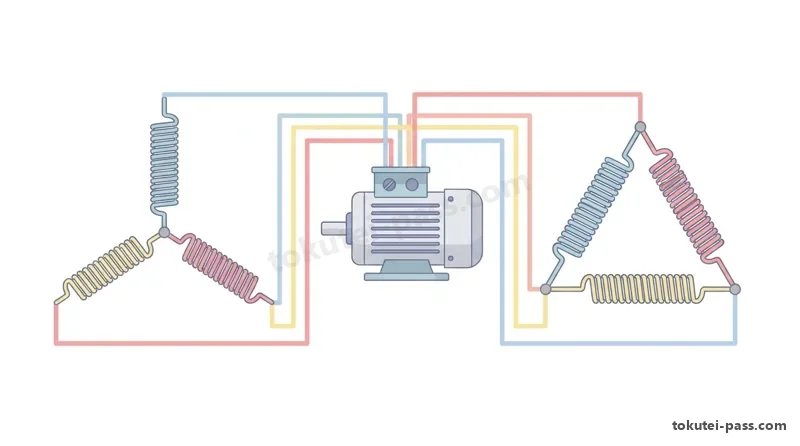
問5では工場や店舗の動力用(200V)に使われる「平衡三相3線式交流回路」が出題されます。3つの負荷のつなぎ方には「スター結線(Y結線:星形)」と「デルタ結線(Δ結線:三角)」の2種類があります。
Question 5 covers "balanced three-phase 3-wire AC circuits" used for 200 V motor power in factories and shops. There are two ways to connect the three phase loads: "Star connection (Y-connection)" and "Delta connection (Δ-connection)".
外側の電線間の電圧を「線間電圧Vl」、電線を流れる電流を「線電流Il」といい、1相分の負荷にかかる電圧を「相電圧Vp」、負荷を流れる電流を「相電流Ip」と呼びます。
Voltage between outer line wires is called "line voltage Vl" and current in the line wires is "line current Il"; voltage across a single phase load is "phase voltage Vp" and current through a single phase load is "phase current Ip".
「Y結線(スター)」では電線がそのまま1相の負荷につながるため線電流と相電流が等しく(Il=Ip)、線間電圧は相電圧の√3倍(Vl=√3×Vp、よってVp=Vl÷√3)になります。
In a "Y-connection (Star)", each line wire feeds directly into one phase load, so line current equals phase current (Il = Ip), while line voltage is √3 times phase voltage (Vl = √3 × Vp, so Vp = Vl ÷ √3).
反対に「Δ結線(デルタ)」では線間電圧がそのまま1相の負荷にかかるため電圧が等しく(Vl=Vp)、線電流は相電流の√3倍(Il=√3×Ip)になります。試験では「√3=1.73」として計算します。
Conversely, in a "Δ-connection (Delta)", line voltage is applied directly across each phase load, so voltages are equal (Vl = Vp), while line current is √3 times phase current (Il = √3 × Ip). In exam calculations, always use "√3 = 1.73".
三相回路全体の消費電力P(W)は、Y結線・Δ結線のどちらでも「P=√3×Vl×Il×cosφ」または「1相分の抵抗消費電力の3倍:P=3×Ip²×R」で簡単に求められます。
Total power consumption P (W) of the entire three-phase circuit, whether Y or Δ connected, is easily found by "P = √3 × Vl × Il × cosφ" or as "three times the resistor power of one phase: P = 3 × Ip² × R".
Key points
- Y結線(スター):電流が等しく「Il=Ip」、線間電圧は相電圧の√3倍「Vl=√3×Vp」となる。
Y-connection (Star): Currents are equal "Il = Ip", and line voltage is √3 times phase voltage "Vl = √3 × Vp". - Δ結線(デルタ):電圧が等しく「Vl=Vp」、線電流は相電流の√3倍「Il=√3×Ip」となる(√3=1.73)。
Δ-connection (Delta): Voltages are equal "Vl = Vp", and line current is √3 times phase current "Il = √3 × Ip" (use √3 = 1.73). - 三相消費電力は「P=√3×Vl×Il×cosφ」または1相分の3倍「P=3×Ip²×R(W)」で計算する。
Three-phase power consumption is calculated by "P = √3 × Vl × Il × cosφ" or three times one phase "P = 3 × Ip² × R (W)". - 【例】1相のインピーダンス Z = 8Ω(R = 6.4Ω、力率 cosφ = 0.8)の Δ結線負荷に線間電圧 200Vを加える → 相電流 Ip = 200 ÷ 8 = 25A、線電流 Il = 1.73 × 25 = 43.25A、三相電力 P = 3 × 25 × 25 × 6.4 = 12,000W(12kW)
Example: Applying 200V line voltage to a Δ-connected load with phase impedance Z = 8Ω (R = 6.4Ω, power factor cosφ = 0.8) → Phase current Ip = 200 ÷ 8 = 25A, line current Il = 1.73 × 25 = 43.25A, 3-phase power P = 3 × 25 × 25 × 6.4 = 12,000W (12kW) - 【例】Y結線で相電圧 Vp = 100V、1相のインピーダンス Z = 5Ω(力率 cosφ = 0.8)のとき → 線間電圧 Vl = 1.73 × 100 = 173V、線電流 Il = 100 ÷ 5 = 20A、三相電力 P = 3 × 100 × 20 × 0.8 = 4,800W
Example: In a Y-connected circuit with phase voltage Vp = 100V and phase impedance Z = 5Ω (power factor cosφ = 0.8) → Line voltage Vl = 1.73 × 100 = 173V, line current Il = 100 ÷ 5 = 20A, 3-phase power P = 3 × 100 × 20 × 0.8 = 4,800W
| Word | Meaning |
|---|---|
| スター結線(Y結線) | star connection (Y-connection) |
| デルタ結線(Δ結線) | delta connection (Δ-connection) |
| 線間電圧と相電圧 | line voltage and phase voltage |
| 線電流と相電流 | line current and phase current |
試験によく出るポイントと覚え方
Frequently Tested Points & Memory Aids
問2の電線抵抗では「断面積A(mm²)なのか直径D(mm)なのか」を必ず確認しましょう。直径Dが2倍なら断面積は2²=4倍になるため、抵抗は1/2ではなく「1/4」になります。
In Question 2 on wire resistance, always check whether the problem gives "cross-sectional area A (mm²) or diameter D (mm)." Doubling diameter D quadruples the area (2² = 4), reducing resistance to "1/4" rather than 1/2.
問3の熱量計算では「1kWh=3,600kJ」と水の比熱「4.2kJ/(kg・K)」を暗記しておけば、公式に当てはめるだけで解けます。問4の交流回路は「3:4:5」または「6:8:10」の直角三角形を描けば暗算でインピーダンスと力率が出ます。
In Question 3 on heat calculations, memorizing "1 kWh = 3,600 kJ" and the specific heat of water "4.2 kJ/(kg·K)" lets you solve directly by substitution. In Question 4 on AC circuits, sketching a "3 : 4 : 5" or "6 : 8 : 10" right triangle gives impedance and power factor mentally.
問5の三相交流は「Y結線は一本道だから電流が同じ(Il=Ip、電圧が√3倍)、Δ結線は並列のように挟むから電圧が同じ(Vl=Vp、電流が√3倍)」と図形のイメージで覚えると絶対に混同しません。
For Question 5 on three-phase AC, visualize the shape: "Y-connection is a straight path from line to phase so Current is equal (Il = Ip, voltage × √3); Δ-connection clamps the load across two lines so Voltage is equal (Vl = Vp, current × √3)."
Key points
- 並列合成抵抗:2個なら「和分の積(R1×R2)÷(R1+R2)」、同じ抵抗Rがn個なら「R÷n」。
Parallel resistance: For 2 resistors use "product over sum (R1 × R2) ÷ (R1 + R2)"; for n identical resistors R use "R ÷ n". - ブリッジ平衡条件:検流計の電流0Aのとき、向かい合う対辺の積「R1×R4=R2×R3」が等しい。
Wheatstone bridge balance (0 A in galvanometer): Products of opposite arms are equal, "R1 × R4 = R2 × R3". - 丸線の抵抗:長さLに比例・直径Dの2乗に反比例(直径2倍・長さ4倍で元の電線と同じ抵抗)。
Round wire resistance: Proportional to length L, inversely proportional to diameter squared D² (2× diameter and 4× length gives equal resistance). - 熱量と電力量:1kWh=3,600kJ、水の温度上昇熱量「Q=4.2×質量m×温度差Δt(kJ)」。
Heat & Electric Energy: 1 kWh = 3,600 kJ; water heating formula "Q = 4.2 × mass m × temperature rise Δt (kJ)". - 交流と三相:6Ωと8Ωの合成は10Ω/Y結線は「Vl=√3Vp・Il=Ip」、Δ結線は「Vl=Vp・Il=√3Ip」(√3=1.73)。
AC & Three-Phase: Combining 6 Ω and 8 Ω gives 10 Ω / Y-connection: "Vl = √3Vp, Il = Ip"; Δ-connection: "Vl = Vp, Il = √3Ip" (√3 = 1.73).
| Word | Meaning |
|---|---|
| 和分の積 | product-over-sum rule |
| 3対4対5の直角三角形 | 3 : 4 : 5 right triangle |
| 1kWh=3,600kJ | 1 kWh = 3,600 kJ conversion |
| 三相電力(P=√3VlIlcosφ) | three-phase power (P = √3VlIlcosφ) |
Basic Electrical Theory
Practice this chapter in the appOfficial references
- 一般財団法人 電気技術者試験センター「第二種電気工事士試験 学科試験(電気に関する基礎理論)」 — https://www.shiken.or.jp/
- 日本産業規格「JIS C 0111 電気・電子技術図記号」 — https://www.jisc.go.jp/