
Plastic Molding (Level 2)
プラスチック成形(2号)
Industrial Manufacturing (SSW 2) · 製造分野(2号) · Written by Tokutei Pass based on the official study texts; not copied verbatim.
エンジニアリングプラスチックの物性と予備乾燥管理
Engineering Plastic Properties and Pre-Drying Management
2号技能では、汎用樹脂だけでなく耐熱性・機械的強度に優れた「エンジニアリングプラスチック(エンプラ)」の物性を深く理解して条件設定を行う必要があります。エンプラは結晶性のPA・POM・PBT・PPSと、非晶性のPC・変性PPEなどに大別されます。
At the Skill Level 2 standard, technicians must deeply understand not only commodity resins but also the physical properties of 'engineering plastics' with superior heat resistance and mechanical strength in order to set molding parameters. Engineering plastics are divided into crystalline types (PA, POM, PBT, PPS) and amorphous types (PC, m-PPE).
ポリカーボネート(PC)、ポリブチレンテレフタレート(PBT)、ポリエチレンテレフタレート(PET)、ポリアミド(PA)などのエステル結合やアミド結合を持つ樹脂は、水分を含んだまま高温の加熱シリンダで溶融すると「加水分解」を起こします。
Resins containing ester or amide linkages—such as polycarbonate (PC), polybutylene terephthalate (PBT), polyethylene terephthalate (PET), and polyamide (PA)—undergo 'hydrolysis' if melted inside a high-temperature heating cylinder while retaining moisture.
加水分解が発生すると、成形品表面に銀条(シルバーストリーク)や気泡が出るだけでなく、高分子鎖が切断されて分子量が低下し、衝撃強度が著しく脆化します。この劣化は再乾燥しても元には戻りません。
When hydrolysis occurs, not only do silver streaks and bubbles appear on the part surface, but polymer chains are severed, lowering molecular weight and severely embrittling impact strength. This degradation is irreversible even if the material is re-dried.
そのため、成形前に除湿乾燥機やホッパードライヤを用い、樹脂ごとに指定された温度と時間(例:PCは120℃で4〜6時間、PAは80〜100℃で4〜8時間)で規定含水率以下まで予備乾燥します。
Therefore, materials must be pre-dried before molding using a dehumidifying dryer or hopper dryer at the specified temperature and time for each resin (e.g., 120°C for 4–6 hours for PC; 80–100°C for 4–8 hours for PA) until moisture falls below the allowable limit.
また、ガラス繊維強化樹脂(GF強化PA・PBT)では、繊維が流動方向(MD)に配向するため流動方向の収縮率が小さく、直角方向(TD)の収縮率が大きくなる「収縮異方性」によるソリ対策が重要です。
Furthermore, in glass-fiber-reinforced resins (GF-PA, GF-PBT), fibers orient along the melt flow direction (MD), making shrinkage much smaller in the flow direction than in the transverse direction (TD); managing warpage caused by this 'shrinkage anisotropy' is essential.
Key points
- PCやPBTの成形前には、加水分解による強度低下を防ぐため十分な予備乾燥を行う。
Before molding PC or PBT, perform thorough pre-drying to prevent strength loss from hydrolysis. - POMを高温のシリンダ内に長時間滞留させると、熱分解して刺激臭のあるガスが発生する。
If POM stagnates inside a hot barrel for a long time, it thermally decomposes and releases irritating gas. - ガラス繊維強化樹脂では、耐摩耗性のスクリュを使用し過度な高背圧を避ける。
For glass-fiber-reinforced resins, use an abrasion-resistant screw and avoid excessive back pressure.
| Word | Meaning |
|---|---|
| 加水分解 | Hydrolysis (cleavage of polymer chains by moisture at high heat) |
| 除湿乾燥機 | Dehumidifying dryer (using low-dew-point dry air) |
| 収縮異方性 | Shrinkage anisotropy (shrinkage difference between MD and TD) |
| 滞留熱分解 | Thermal degradation from prolonged barrel residence |
射出成形機の機構制御と精密条件設定
Injection Molding Machine Mechanism Control and Precision Parameter Setup
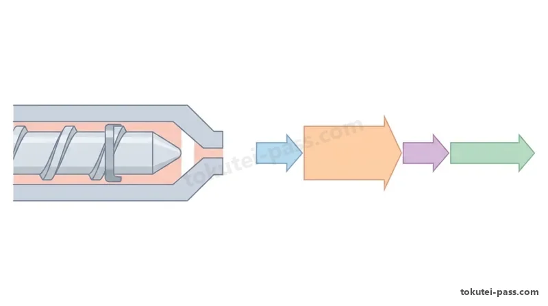
インラインスクリュ式射出成形機のスクリュ先端には、計量時に前方へ溶融樹脂を送り、射出・保圧時に後方への逆流を防ぐ「逆流防止弁(チェックリング・シートリング)」が設けられています。チェックリングが摩耗するとクッション量がばらつき、ショートショットやヒケの原因になります。
At the screw tip of an in-line screw injection molding machine, a 'non-return valve (check ring and seat ring)' allows molten resin to flow forward during metering and seals against backflow during injection and holding pressure. Check-ring wear causes cushion variation, leading to short shots and sink marks.
射出工程では「多段射出速度制御」を行います。ゲート通過時は「低速」にしてジェッティングやゲート付近のフローマークを防ぎ、一般肉厚部は「高速」で充填し、充填完了直前は「減速」して断熱圧縮によるガス焼けや急激な圧力ピークによるバリを防ぎます。
During injection, 'multi-stage velocity control' is applied: a 'slow speed' as melt passes the gate prevents jetting and gate flow marks, a 'high speed' fills the main wall rapidly, and 'deceleration' right before the end of fill prevents adiabatic gas burns and pressure-spike flash.
溶融樹脂がキャビティの約95〜98%を満たした位置(V-P切替位置)で、速度制御から圧力制御(保圧)へ切り替えます。V-P切替が早すぎると充填不足になり、遅すぎると過充填(オーバーパック)となってバリや離型不良を引き起こします。
At the position where molten resin fills roughly 95–98% of the cavity (the V-P switchover position), control switches from velocity to pressure (holding pressure). Switching V-P too early causes short shots, while switching too late causes overpacking, flash, and sticking in the mold.
最適な保圧時間を決めるには、保圧時間を段階的に延ばしながら成形品質量を測定し、質量が一定になって増えなくなる「ゲートシール時間」を求めます。また、最前進位置では常に3〜5 mm程度の「クッション量」を残して保圧を有効に作用させます。
To determine the optimal holding time, holding time is extended in steps while weighing the molded parts to find the 'gate seal time' where part weight levels off. In addition, a 'cushion' of about 3–5 mm must always remain at the most forward screw position so holding pressure acts effectively.
型締機構には、リンクの倍力作用で高速開閉・省電力保持ができる「トグル式」と、油圧シリンダで直接押して型厚変化の影響を受けない「直圧式」があります。バリを防ぐ必要型締力は「投影面積×キャビティ内平均樹脂圧力」で計算します。
Mold clamping mechanisms include the 'toggle type', which uses link magnification for fast movement and energy-efficient lockup, and the 'direct hydraulic type', which presses directly with a cylinder unaffected by thermal mold expansion. Required clamping force is calculated as 'Projected Area × Average Cavity Resin Pressure'.
Key points
- チェックリングが摩耗すると、保圧中に樹脂が逆流してクッション量が0 mmまで減少する。
When the check ring wears out, resin leaks backward during holding pressure and the cushion drops to 0 mm. - 充填完了直前に射出速度を減速することで、ガス焼けとバリの発生を同時に抑えられる。
By decelerating injection speed just before the end of fill, both gas burns and flash can be suppressed simultaneously. - 成形品の必要冷却時間は、最大肉厚の2乗にほぼ比例して長くなる。
The required cooling time of a molded part increases roughly in proportion to the square of its maximum wall thickness.
| Word | Meaning |
|---|---|
| 逆流防止弁(チェックリング) | Non-return valve / Check ring (prevents melt backflow during injection) |
| V-P切替位置 | V-P switchover position (velocity to holding pressure transfer point) |
| ゲートシール時間 | Gate seal time (freeze-off time when part weight stops increasing) |
| 必要型締力 | Required clamping force (Projected area A × Cavity pressure P) |
高度な金型構造・ゲート方式・温調・保守管理
Advanced Mold Structures, Gate Systems, Thermal Control, and Maintenance
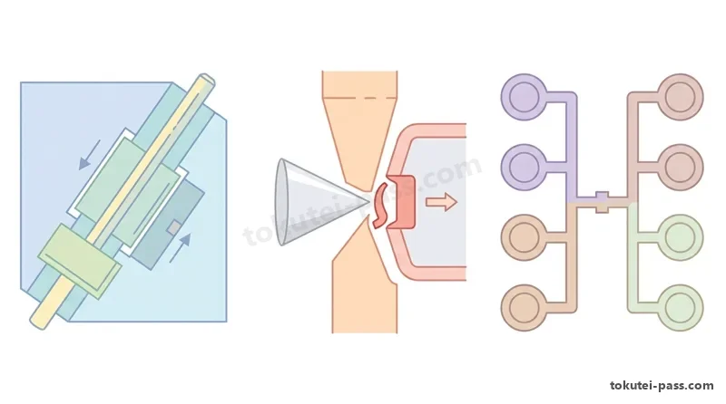
成形品側面に横穴や凹凸(アンダーカット)がある場合、型開き動作に連動して「アンギュラピン」で「スライドコア」を横方向へ抜く機構を用います。また、射出圧力でスライドコアが後退しないよう「ロッキングブロック」で背面を強固に受け止めます。
When a molded part has side holes or recesses (undercuts), an 'angular pin' drives a 'slide core' laterally in synchronization with mold opening. During clamping, a wedge-shaped 'locking block (heel block)' backs up the rear of the slide core so injection pressure cannot push it backward.
自動切断ゲートには、3枚プレート金型で点状に切り離す「ピンポイントゲート」や、2枚プレート金型のまま型開きや突き出し時に潜り込んだゲートを自動切断する「サブマリンゲート(トンネルゲート)」があります。
Self-degating systems include the 'pin-point gate' used in three-plate molds to leave a tiny dot vestige, and the 'submarine gate (tunnel gate)' that angles beneath the parting surface to shear the gate automatically upon ejection in a simpler two-plate mold.
ランナー廃棄物を出さない「ホットランナー金型」では、マニホールドとノズルをヒータで加熱保持します。特に「バルブゲート式」は保圧完了後にバルブピンでゲートを機械的に閉鎖するため、糸引きや鼻たれがなくゲート跡もきれいに仕上がります。
In runnerless 'hot runner molds', the manifold and nozzles keep resin molten with heaters. In particular, the 'valve-gate type' mechanically closes the gate orifice with a valve pin after holding pressure finishes, eliminating stringing and drooling while leaving a clean gate mark.
多数個取り金型では、スプルーから各キャビティまでの流動距離とせん断履歴を等しくする「H型自然バランスランナー」を採用します。また、パーティング面のガスベント深さは、低粘度のPAでは0.01〜0.02 mmと浅くし、PCでは0.03〜0.05 mmに設定します。
Multi-cavity molds employ an 'H-type naturally balanced runner' so flow distance and shear history from the sprue to every cavity are identical. Parting-line gas vent depth is matched to melt viscosity: shallow at 0.01–0.02 mm for low-viscosity PA and 0.03–0.05 mm for higher-viscosity PC.
金型交換後は異物挟み込みによる金型破損を防ぐ「低圧型締(金型保護)機能」を設定します。日常保守では、冷却水管内のスケール詰まり除去や、エジェクタピン摺動部への適量の耐熱グリース給脂を徹底します。
After mold setup changes, the 'low-pressure mold clamping (mold protection) function' is set to prevent mold crushing from trapped parts. Routine maintenance includes descaling cooling water channels and applying a thin film of heat-resistant grease to ejector pin shanks.
Key points
- ロッキングブロックは、射出時の樹脂圧力によってスライドコアが後退するのを防ぐ。
The locking block prevents the slide core from being pushed back by resin pressure during injection. - 自然バランスランナーを採用することで、全てのキャビティへの充填バランスを均一にする。
Adopting a naturally balanced runner equalizes the filling balance across all cavities. - 冷却回路にスケールが付着すると熱伝達率が低下し、金型実温度が上昇する。
When scale builds up in cooling circuits, heat transfer drops and actual mold temperature rises.
| Word | Meaning |
|---|---|
| スライドコアとアンギュラピン | Slide core and angular pin mechanism for releasing side undercuts |
| サブマリンゲート | Submarine gate / Tunnel gate (auto-shearing gate in a 2-plate mold) |
| バルブゲート式ホットランナー | Valve-gate hot runner (mechanical gate shut-off via valve pin) |
| 低圧型締(金型保護) | Low-pressure mold clamping / Mold protection against trapped parts |
射出成形の高度不良診断と成形品肉厚設計
Advanced Injection Molding Defect Diagnosis and Part Wall Design
2号の実技試験では、複数の要因が絡み合う成形不良のメカニズムを特定し、成形条件だけでなく金型修正や製品設計面から対策を立てる能力が求められます。たとえば厚肉部内部の「ボイド(真空泡)」は、表面固化後の内部収縮が原因であり、保圧圧力や金型温度を高めて対策します。
In the Level 2 practical exam, technicians must pinpoint the root mechanisms of complex defects and formulate countermeasures spanning molding parameters, mold modifications, and part design. For example, internal 'vacuum voids' in thick sections occur when the outer skin freezes quickly and the core shrinks inward; they are corrected by raising holding pressure and raising mold temperature.
一方、水分や分解ガスによる「気泡・シルバーストリーク」は、予備乾燥の徹底や背圧の適正化、サックバック量の縮小(空気巻き込み防止)で解決します。同じ泡状の不良でも「真空ボイド」と「ガス気泡」では対策が正反対になる点に注意が必要です。
Conversely, 'gas bubbles and silver streaks' caused by moisture or decomposition gas are resolved by thorough pre-drying, proper back pressure, and reducing suck-back stroke (to avoid drawing air into the nozzle). Although both look like bubbles, vacuum voids and gas bubbles require distinct countermeasures.
また、狭いゲートから高速射出した溶融樹脂が蛇のようにうねって固化する「ジェッティング」は、ゲート通過時の射出速度を落とすか、樹脂がキャビティ壁面に当たるタブゲート・オーバーラップゲートへ変更して防止します。
'Jetting'—where high-speed melt shooting through a narrow gate snakes into an open cavity and freezes—is prevented by slowing injection speed across the gate or modifying the gate to a tab or overlap gate that directs melt against a cavity wall.
箱型成形品では、内側のコア角部に熱がこもって外側のキャビティ面より高温になりやすく、冷却後に高温側(内側)の収縮が大きくなって側壁が内側へ倒れる「内反り」が起きます。この場合、可動側(コア)の設定温度を固定側より低くして表裏の冷却速度を揃えます。
In box-shaped parts, heat accumulates on the inner core corners so the inside runs hotter than the outer cavity wall; greater shrinkage on the hotter inner side pulls the sidewalls inward ('inward warpage'). Setting the moving core temperature lower than the stationary cavity temperature balances inner and outer cooling rates.
製品設計上のヒケ対策としては、平板裏側に設ける「リブ」の厚さを基本肉厚の50〜60%程度に薄くし、ボス根元には「肉盗み」を設けて偏肉(肉厚集中)をなくすことが原則です。
As a fundamental part design rule against sink marks, the thickness of stiffening 'ribs' on the back of a flat wall should be kept at 50–60% of the nominal wall thickness, and 'coring out (meat stealing)' should be applied at the base of bosses to eliminate heavy mass intersections.
Key points
- 厚肉部のボイドを防ぐため、金型温度を上げて表面固化を遅らせ保圧を効かせる。
To prevent voids in thick sections, raise mold temperature to delay skin freezing so packing pressure remains effective. - 平板の裏側に設けるリブの厚さは、基本肉厚の50〜60%程度に設計する。
The thickness of a rib on the back of a flat plate is designed at about 50–60% of the nominal wall thickness. - 金属インサート部品を成形前に予熱し、残留応力によるウェルド割れを防ぐ。
Pre-heat metal inserts before molding to prevent weld-line cracking caused by residual stress.
| Word | Meaning |
|---|---|
| ボイド(真空泡) | Vacuum void inside thick sections caused by rapid skin freezing |
| ジェッティング | Jetting (worm-like melt stream shooting through an unobstructed gate) |
| 表裏冷却バランス | Inner/outer cooling balance between core and cavity to prevent warpage |
| リブ肉厚比と肉盗み | Rib-to-wall thickness ratio (50–60%) and coring out to prevent sink marks |
熱硬化性樹脂成形(圧縮・トランスファ)の実務管理
Practical Management of Thermoset Molding (Compression and Transfer)
フェノール樹脂(PF)、ユリア樹脂(UF)、メラミン樹脂(MF)、エポキシ樹脂(EP)、不飽和ポリエステル樹脂(UP)などの「熱硬化性樹脂」は、150〜180℃程度に高温加熱した金型内で化学反応(架橋反応)を起こして三次元網目構造となり、永久に硬化します。
'Thermosetting resins' such as phenolic (PF), urea (UF), melamine (MF), epoxy (EP), and unsaturated polyester (UP) undergo a chemical cross-linking reaction inside a mold heated to about 150–180°C, forming a three-dimensional network structure and hardening permanently.
圧縮成形(コンプレッション成形)では、成形材料(タブレット)を高周波予熱機等であらかじめ予備加熱してからキャビティへ投入することで、流動性を高めて硬化時間を短縮し、肉厚内部まで均一に硬化させます。
In compression molding, pre-heating material tablets (preforms) with a high-frequency pre-heater before loading them into the cavity improves flowability, shortens cure time, and ensures uniform curing throughout thick sections.
また、圧縮加圧の初期段階で金型をわずかに一瞬開く「ガス抜き(ブリージング)」を行います。これにより、硬化反応(縮合反応)によって発生した水蒸気や揮発性ガスを外部へ逃がし、成形品表面の「ふくれ(ブリスター)」や気泡を防ぎます。
In addition, during the initial stage of compression, the mold is momentarily cracked open slightly in an operation called 'breathing (degassing)'. This vents water vapor and volatile gases generated by the condensation curing reaction, preventing surface 'blisters' and internal porosity.
予備加熱温度や金型温度が高すぎたり、材料投入から型閉じ加圧までの動作が遅すぎたりすると、材料がキャビティの隅々まで流れきる前に硬化してしまう「早期硬化(プリキュア)」が発生し、充填不足や光沢不良となります。
If the pre-heating temperature or mold temperature is too high, or if the movement from loading to mold closing and pressing is too slow, 'pre-curing (premature hardening)' occurs before the compound fills the cavity corners, resulting in short shots and dull gloss.
トランスファ成形では、金型を閉じたあと加熱室(ポット)の材料をプランジャで加圧してキャビティへ圧入するため、複雑形状品や金属インサート品の精密成形に適しています。この際、ポット底面に適正厚みの「カル(残材)」を残して圧力を確実に伝えます。
In transfer molding, the mold is closed first and a plunger forces plasticized material from a transfer pot through runners into the cavities, making it ideal for intricate parts and delicate metal inserts. A proper 'cull' thickness must be maintained at the pot bottom to transmit effective packing pressure.
Key points
- 圧縮成形でブリージングを行わないと、内部にこもったガスで成形品にふくれが発生する。
If breathing is omitted in compression molding, trapped gas causes blisters on the molded part. - 金型温度が高すぎると早期硬化(プリキュア)を起こし、充填不足になる。
If the mold temperature is too high, pre-curing occurs and results in incomplete filling. - トランスファ成形では、ポット底面に適正な厚みのカルを残して圧力を伝える。
In transfer molding, leave a cull of proper thickness at the pot bottom to transmit packing pressure.
| Word | Meaning |
|---|---|
| 予備加熱(高周波予熱) | Pre-heating of thermoset preforms before mold loading |
| ガス抜き(ブリージング) | Breathing / Degassing (momentary mold opening to vent curing gases) |
| 早期硬化(プリキュア) | Pre-curing (premature hardening before complete cavity filling) |
| カル(ポット残材) | Cull (residual pad at the transfer pot bottom that transmits pressure) |
押出成形・ブロー成形・真空成形の工程管理
Process Management in Extrusion, Blow Molding, and Vacuum Forming
押出成形機のスクリュは、ホッパー側から「供給部(フィードゾーン)」「圧縮部(コンプレッションゾーン)」「計量部(メータリングゾーン)」の3つの領域で構成されます。先端のブレーカープレートとスクリーンパックは、異物をろ過し適度な背圧を与えて樹脂のらせん流を直進流に整えます。
An extruder screw consists of three zones from the hopper forward: the 'feed zone', the 'compression zone', and the 'metering zone'. The breaker plate and screen pack at the screw tip filter out contaminants, generate back pressure, and straighten helical screw flow into linear flow.
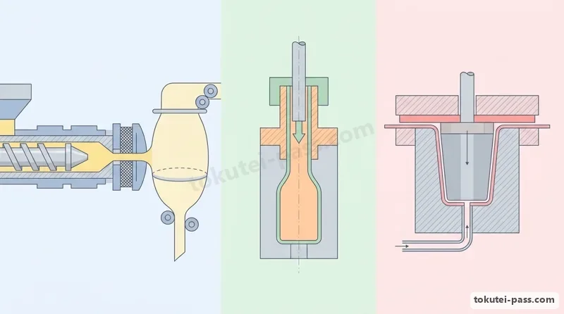
ダイから押し出された溶融樹脂がダイ隙間より太く膨らむ現象を「ダイスウェル(バラス効果)」と呼びます。また、インフレーションフィルム成形では、エアリングからの冷却風でバブルが固化する境界線である「フロストライン」の高さを一定に保つことで、折径や透明度を安定させます。
The phenomenon where molten resin swells wider than the die slit upon exiting is called 'die swell (the Barus effect)'. In blown film extrusion (inflation molding), maintaining a constant 'frost line' height—the boundary where air from the air ring solidifies the bubble—stabilizes lay-flat width and film clarity.
中空容器を作るダイレクトブロー成形では、垂れ下げたパリソンが自重で引き伸ばされて上部が薄くなる「ドローダウン」が発生します。これを補正し、容器の膨らみ倍率に合わせて肉厚を均一化するため、「パリソンコントローラ」でダイギャップ(マンドレル位置)を多点制御します。
In direct blow molding of hollow containers, the hanging parison stretches under its own weight, thinning the upper wall ('drawdown'). To compensate for drawdown and match different blow-up ratios along the bottle, a 'parison controller' dynamically adjusts the die gap (mandrel position) across multiple points.
また、飲料用PETボトルなどで用いられる「二軸延伸ブロー成形」では、射出成形した有底の「プリフォーム」をガラス転移温度以上・融点以下の延伸適温に温調し、ストレッチロッドで縦方向に、高圧空気で横方向に同時延伸して強度・透明性・ガスバリア性を高めます。
Furthermore, in 'biaxial stretch blow molding' used for beverage PET bottles, an injection-molded test-tube-shaped 'preform' is conditioned between its glass transition temperature and melting point, then stretched axially by a stretch rod while blown radially with high-pressure air to boost strength, clarity, and gas-barrier performance.
加熱軟化させたシートを金型に密着させる「真空成形・圧空成形」では、深絞り容器の底角部が極端に薄くなる(偏肉)のを防ぐため、真空吸引の直前に補助型(プラグ)でシートを予備延伸する「プラグアシスト成形」が多用されます。
In 'vacuum and pressure forming' of heated plastic sheets, 'plug-assist forming'—which pre-stretches the sheet into the cavity with a mechanical plug right before vacuum suction—is widely used to prevent extreme thinning at the bottom corners of deep-draw containers.
Key points
- スクリーンパックが目詰まりすると、ブレーカープレート手前の樹脂圧力が異常上昇する。
When the screen pack clogs, resin pressure upstream of the breaker plate rises abnormally. - 二軸延伸ブロー成形では、プリフォームを縦横二方向に延伸してボトルの強度を高める。
In biaxial stretch blow molding, the preform is stretched both axially and radially to increase bottle strength. - 深絞り容器の真空成形では、プラグアシストを用いて底角部の偏肉を防ぐ。
In vacuum forming of deep-draw containers, plug-assist is used to prevent bottom-corner thinning.
| Word | Meaning |
|---|---|
| ブレーカープレートとスクリーンパック | Breaker plate and screen pack (filtering, back pressure, flow straightening) |
| ダイスウェル(バラス効果) | Die swell / Barus effect (elastic swelling of extrudate exiting the die) |
| フロストライン(凍結線) | Frost line (solidification boundary line on a blown film bubble) |
| パリソンコントローラ | Parison controller (axial wall-thickness programmer compensating for drawdown) |
QC七つ道具と統計的工程管理(Cp・管理図)
Seven QC Tools and Statistical Process Control (Cp and Control Charts)
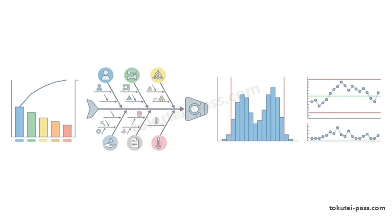
2号の現場監督者には、「QC七つ道具」を駆使して客観的なデータから不良原因を解析する能力が求められます。「パレート図」は不良項目別の件数(棒グラフ)と累積比率(折れ線グラフ)を組合わせ、最優先で対策すべき重点項目を選定します。
A Level 2 shop-floor supervisor must master the 'Seven QC Tools' to analyze defect causes from objective data. A 'Pareto chart' combines a bar graph of defect counts by category with a cumulative percentage line to identify the vital few priority items for countermeasures.
「特性要因図(魚の骨図)」は、結果(特性:ウェルドラインなどの不良)に対して4M(機械・金型・材料・作業方法)の要因を体系的に整理します。また「散布図」は保圧圧力と製品質量のような2つの対になるデータを打点し、「正の相関」や「負の相関」を調べます。
A 'cause-and-effect diagram (fishbone diagram)' systematically organizes 4M factors (Machine, Mold/Tooling, Material, Method) contributing to a specific quality characteristic or defect. A 'scatter diagram' plots paired variables (such as holding pressure and part weight) to examine 'positive' or 'negative' correlation.
測定値のばらつき分布を見る「ヒストグラム」において、山が左右2つに分かれる「二山型(双峰型)」になった場合は、平均値が異なる2つのキャビティや2台の成形機の製品が混入していると診断し、キャビティ別に「層別」を行います。
In a 'histogram' showing measurement distribution, a 'bimodal (two-peaked)' shape with left and right peaks indicates that parts from two cavities or two machines with different means were mixed together, requiring 'stratification' by cavity number.
工程が時間経過とともに安定しているかを監視する「Xbar-R管理図」では、点が管理限界線(UCL・LCL)のすぐ内側にあっても、中心線(CL)の片側に連続して並ぶ「連(ラン)」や一方向へ動き続ける「傾向(トレンド)」が現れた場合は、工程異常の予兆として原因調査を行います。
On an 'Xbar-R control chart' monitoring process stability over time, even if points remain inside the control limits (UCL and LCL), a 'run' of consecutive points on one side of the center line (CL) or a continuous 'trend' in one direction signals a non-random process shift that requires investigation.
規格幅(USL−LSL)に対する工程のばらつき(6σ)の余裕度を表す「工程能力指数 Cp =(USL−LSL)÷6σ」は、一般に Cp ≥ 1.33 で工程能力が十分と判定され、1.00未満では全数検査や抜本的な工程改善が必要とされます。
The 'process capability index Cp = (USL − LSL) / 6σ' measures how comfortably the specification width accommodates the 6σ process spread; generally Cp ≥ 1.33 indicates sufficient capability, whereas Cp < 1.00 requires 100% inspection and fundamental process improvement.
Key points
- ヒストグラムが二山型になった場合は、キャビティ番号別にデータを層別して確認する。
When a histogram shows a bimodal shape, stratify the data by cavity number to investigate. - 管理図で中心線の片側に点が連続して並んだ場合は、工程異常の予兆と判断する。
On a control chart, a run of consecutive points on one side of the center line is judged an early sign of process abnormality. - 散布図で保圧圧力と製品質量の関係を調べたところ、右肩上がりの正の相関が見られた。
Plotting holding pressure against part weight on a scatter diagram revealed an upward-sloping positive correlation.
| Word | Meaning |
|---|---|
| パレート図と累積比率 | Pareto chart and cumulative percentage for prioritizing key defects |
| 特性要因図(魚の骨図) | Cause-and-effect diagram (fishbone diagram) organizing 4M root causes |
| Xbar-R管理図 | Xbar-R control chart monitoring sample mean and range over time |
| 工程能力指数(Cp) | Process capability index Cp = (USL − LSL) / 6σ (capable when Cp ≥ 1.33) |
4M変更管理・初品検査・限度見本・色替え段取り
4M Change Management, First-Article Inspection, Limit Samples, and Color Changeover
量産現場において、材料ロットの切替え、金型修理・交換、成形機や成形条件の変更、作業者交代などの「4M変更(Man・Machine・Material・Method)」があった際には、変更点を記録して品質リスクを重点管理する「4M変更管理」を行います。
On the mass-production floor, whenever a '4M change (Man, Machine/Mold, Material, Method)' occurs—such as a material lot change, mold repair or replacement, parameter adjustment, or operator shift change—'4M change management' must be practiced to log the change and control quality risks.
金型交換や修理後の立ち上げ時に行う「初品検査」では、成形温度やサイクルが安定した状態でサンプルを採取します。特に8個取りなどの多数個取り金型では、No.1〜No.8すべてのキャビティの成形品を採取し、キャビティ番号別に寸法と外観を全キャビティ検査します。
During 'first-article inspection' at startup after a mold change or repair, samples must be taken once molding temperatures and cycle rhythm have stabilized. Especially for multi-cavity molds such as an 8-cavity tool, parts from every cavity (No. 1 through No. 8) must be collected and inspected individually for dimensions and appearance.
また、精密寸法測定は成形直後の熱い状態で行うと熱膨張や結晶化による後収縮の途中であるため誤差が大きくなります。JIS K 7100の標準状態(温度23℃・相対湿度50%)で所定時間養生(状態調節)してから測定するのが原則です。
Furthermore, measuring precision dimensions immediately after ejection while the part is still hot introduces large errors due to thermal expansion and ongoing post-molding crystalline shrinkage. Parts must be conditioned under standard atmosphere (JIS K 7100: 23°C and 50% relative humidity) for the specified time before measurement.
ウェルドライン、フローマーク、黒点などの外観検査で合格・不合格の境界基準となる「限度見本(リミットサンプル)」は、品質管理部門の承認印と有効期限を明記し、日光や照明による変色・劣化および出荷品への混入を防ぐため遮光保管します。
'Limit samples' used as the pass/fail boundary for visual defects (weld lines, flow marks, black specks) must bear the approval stamp of the quality assurance department and an expiration date, and must be stored shielded from light in a designated location to prevent discoloration or accidental mixing with shipments.
濃色から淡色への「色替え」や「材料替え」では、コンタミネーション(異材・異色混入)を防ぐため、吸引輸送ホース・ホッパー・ドライヤ・マグネットを隅々まで清掃し、パージ剤等でシリンダ内とノズル先端接触面の滞留樹脂を完全に排出します。
During a 'color changeover' from dark to light or a 'material changeover', contamination is prevented by thoroughly cleaning loader hoses, hoppers, dryers, and magnet grids, followed by purging stagnant resin from the barrel and nozzle tip contact face using purging compound.
Key points
- 8個取り金型の初品検査では、No.1からNo.8まで全てのキャビティを個別に測定する。
In first-article inspection of an 8-cavity mold, measure all cavities from No. 1 to No. 8 individually. - 限度見本には承認印と有効期限を表示し、変色を防ぐため遮光保管する。
Display the approval stamp and expiration date on limit samples, and store them shielded from light to prevent discoloration. - 色替え時は、ホッパーやマグネットに残った前のペレットを完全に除去してからパージを行う。
During a color changeover, completely remove residual pellets from the hopper and magnet grid before purging.
| Word | Meaning |
|---|---|
| 4M変更管理 | 4M change management (Man, Machine/Mold, Material, Method) |
| キャビティ番号別初品検査 | Cavity-by-cavity first-article inspection across all cavities |
| 状態調節(23℃・50%RH) | Standard conditioning (23°C, 50% RH per JIS K 7100) prior to measurement |
| 限度見本(リミットサンプル) | Limit sample approved by QC as the visual inspection pass/fail boundary |
成形現場の安全衛生・インターロック・KY活動
Molding Shop Safety & Health, Interlocks, and KY Hazard Prediction
プラスチック成形現場では、数十〜数千kNの強大な型締力で開閉する金型、200〜350℃の高温になる加熱シリンダやノズル、高速で動く自動取出ロボットなど、重篤な労働災害につながる危険源が存在します。
The plastic molding floor contains hazards capable of causing severe industrial accidents, including molds clamping with tens to thousands of kilonewtons of force, heating cylinders and nozzles at 200–350°C, and high-speed automated takeout robots.
射出成形機の「安全ドア」には、電気的・油圧的・機械的な「安全インターロック」が設けられており、安全ドアが開いている間は型閉じ・射出・ロボット動作が停止します。いかなる理由があっても、リミットスイッチをテープで固定して無効化する行為は絶対に厳禁です。
The 'safety door' of an injection molding machine is equipped with electrical, hydraulic, and mechanical 'safety interlocks' that halt mold closing, injection, and robot motion whenever the door is open. Defeating a limit switch with tape or jumpers is strictly prohibited under any circumstances.
金型内に詰まった成形品やランナーを除去する際や、金型清掃・給脂を行う際には、必ず成形機を「手動モード」にしてモータ・ポンプ(駆動源)を停止させ、取出ロボットも停止・原点退避させたうえで、金型を傷つけない真鍮製ペンチなどの専用工具を使用します。
When clearing a stuck part or runner inside the mold, or when cleaning and greasing the mold, always switch the machine to 'manual mode', shut off the motor/pump drive power, stop and home the takeout robot, and use dedicated non-marring tools such as long brass pliers.
また、加熱シリンダ内の樹脂を排出する「パージ作業」や、滞留したPOM・PVC・難燃樹脂を処理する際には、内圧で高温の溶融樹脂や分解ガスが噴出する危険があります。必ず「パージカバー(ノズル安全カバー)」を閉め、保護面(フェイスシールド)・耐熱手袋・長袖作業着を着用し、局所排気装置を稼働させます。
Furthermore, during 'purging' of the heating cylinder or handling of stagnant POM, PVC, or flame-retardant resins, built-up internal pressure can violently eject hot melt and decomposition gas. Always close the 'purge guard (nozzle safety cover)', wear a face shield, heat-resistant gloves, and long sleeves, and run local exhaust ventilation.
金型交換(段取り替え)でクレーン・玉掛け作業を行う際は、有資格者が金型質量とアイボルトのねじ込み状態・吊り角度(60度以内)を確認し、「吊り荷の下には絶対に入らない」などのKY(危険予知)活動を指差呼称で徹底します。
During mold changes using an overhead crane and slinging gear, qualified personnel must verify mold weight, full seating of eyebolts, and sling angle (within 60°), while enforcing KY (hazard prediction) pointing-and-calling rules such as 'Never stand under a suspended load'.
Key points
- 安全ドアのリミットスイッチを無効化して運転することは、重大災害につながるため厳禁である。
Defeating the safety door limit switch during operation leads to severe accidents and is strictly prohibited. - パージ作業時は必ずパージカバーを閉め、保護面と耐熱手袋を着用する。
During purging, always close the purge guard and wear a face shield and heat-resistant gloves. - クレーンで金型を移動する際は、吊り荷の下に絶対に入ってはならない。
When moving a mold with a crane, never step beneath the suspended load.
| Word | Meaning |
|---|---|
| 安全インターロック | Safety interlock (cuts off motion when safety door or guard is open) |
| パージカバーと保護面 | Purge guard and face shield protecting against molten resin splash |
| 駆動源遮断(ロックアウト) | Drive power shut-off / Lockout before entering hazardous mold zones |
| 危険予知(KY)と指差呼称 | Hazard prediction (KY) activity and pointing-and-calling verification |
Advanced Plastic Molding (Conditions, Defect Fixes, Mold Change, QC)
Practice this chapter in the appOfficial references
- 製造分野特定技能2号評価試験(経済産業省・JAIM) — https://www.jaim-skill.or.jp/exam/about-ssw2/
- 技能検定 プラスチック成形 試験問題(JAVADA) — https://www.javada.or.jp/jigyou/gino/giken/