 Tokutei Pass
Electrical and Electronic Assembly
電気・電子組立
Industrial Manufacturing - Machinery and Electronics · 製造分野 · Written by Tokutei Pass based on the official study texts; not copied verbatim.
オームの法則と消費電力・電流の単位換算
Ohm's Law, Power Consumption, and Current Unit Conversion
オームの法則では、「電圧V(V)=電流I(A)×抵抗R(Ω)」の関係が成り立ちます。
According to Ohm's law, Voltage V (V) = Current I (A) × Resistance R (Ω).
例えば抵抗が10Ωで流れる電流が2Aのとき、電圧は10×2=20Vになります。
For example, when resistance is 10 Ω and current is 2 A, the voltage is 10 × 2 = 20 V.
消費電力P(W)は「電圧V(V)×電流I(A)」で求め、100Vの電源で2Aの電流が流れるときは100×2=200Wです。
Power consumption P (W) equals Voltage V (V) × Current I (A); a device drawing 2 A from a 100 V supply consumes 100 × 2 = 200 W.
電流の単位は1A=1000mA(ミリアンペア)であり、250mAを換算すると0.25A(2.5Aではない)になります。
For electric current units, 1 A = 1000 mA (milliamperes), so 250 mA equals 0.25 A (not 2.5 A).
Key points
- 【○正しい】オームの法則により、抵抗10Ωに電流2Aが流れるときの電圧は「10×2=20V」である。
(○ True) By Ohm's law, a 10 Ω resistor carrying a 2 A current has a voltage of 10 × 2 = 20 V. - 【○正しい】100Vの電源で2Aの電流が流れる機器の消費電力は「100×2=200W」である。
(○ True) A device connected to a 100 V power supply drawing 2 A consumes 100 × 2 = 200 W of power. - 【×誤り】電流の単位換算で「250mA=2.5A」というのは誤り(1A=1000mAなので、250mA=0.25A)。
(× False) Converting 250 mA to '2.5 A' is FALSE (since 1 A = 1000 mA, 250 mA equals 0.25 A).
| Word | Meaning |
|---|---|
| オームの法則 | Ohm's law |
| 電圧 | voltage (V) |
| 電流 | electric current (A) |
| 電気抵抗 | electrical resistance (Ω) |
| 消費電力 | power consumption (W) |
抵抗の直列・並列接続とカラーコード
Series & Parallel Resistors and Resistor Color Codes
抵抗を直列につないだときの合成抵抗は各抵抗の和になり、10Ωと20Ωの直列接続では10+20=30Ωです。
When resistors are connected in series, total resistance is their sum: a 10 Ω resistor and a 20 Ω resistor in series equal 30 Ω.
同じ値の抵抗2本を並列につないだときの合成抵抗は半分の値になり、20Ωを2本並列につなぐと10Ωになります。
When two equal resistors are connected in parallel, total resistance is halved: two 20 Ω resistors in parallel equal 10 Ω.
抵抗器のカラーコードでは、黒=0、茶=1、赤=2、だいだい=3…の数字を表し、3本目の色は倍率(10の累乗)を表します。
In resistor color codes, Black = 0, Brown = 1, Red = 2, Orange = 3, and the third band represents the multiplier (power of 10).
カラーコードが「茶・黒・赤」の順のとき、1(茶)と0(黒)に10²=100倍(赤)をかけて1000Ω=1kΩとなります。
When the color bands read 'Brown - Black - Red', combine 1 (Brown) and 0 (Black) and multiply by 10² = 100 (Red) to get 1000 Ω = 1 kΩ.
Key points
- 【○正しい】10Ωと20Ωの抵抗を直列につないだ合成抵抗は、2つの和である「30Ω」になる。
(○ True) Connecting 10 Ω and 20 Ω resistors in series gives a combined resistance of 30 Ω. - 【○正しい】20Ωの抵抗を2本並列につないだ合成抵抗は、半分の値である「10Ω」になる。
(○ True) Connecting two 20 Ω resistors in parallel gives half the value, or 10 Ω. - 【○正しい】カラーコードが「茶(1)・黒(0)・赤(10²)」の抵抗値は、1000Ω(1kΩ)である。
(○ True) A resistor with color bands 'Brown (1) - Black (0) - Red (×10²)' has a resistance of 1 kΩ (1000 Ω).
| Word | Meaning |
|---|---|
| 直列接続 | series connection |
| 並列接続 | parallel connection |
| 合成抵抗 | combined (equivalent) resistance |
| 抵抗器 | resistor |
| カラーコード | color code |
テスター(マルチメータ)の正しい使い方
Proper Use of a Multimeter (Tester)
テスター(マルチメータ)で電池や回路の電圧を測定するときは、必ず「電圧レンジ」に切り替えて測定箇所に並列にテスト棒を当てます。
When measuring battery or circuit voltage with a multimeter, set it to the voltage range and touch the test leads in parallel.
電流レンジに切り替えたまま電池の両端にテスト棒を直接当てると、大電流が流れて短絡(ショート)し危険です。
Touching test leads directly across a battery while set to the current range causes a dangerous short circuit and damages the meter.
回路内の抵抗値を測定するときは、必ず回路の電源を切り、電流が流れていない状態で測定します。
When measuring resistance in a circuit, always turn off the circuit power so no current is flowing.
導通チェック(ブザー)でケーブルの断線を調べるときも電源を切り、両端にテスト棒を当ててブザーが鳴れば導通があると判断します。
For a continuity check (buzzer test) to check for broken wires, turn off the power and touch both ends of the cable; a beep indicates continuity.
Key points
- 【×誤り】電池の電圧測定で、テスターを「電流レンジ」にして電池の両端に直接当てるのは誤り(電圧レンジにする)。
(× False) Measuring battery voltage by setting the multimeter to the 'current range' and touching both battery terminals is FALSE. - 【×誤り】回路内の抵抗値を、電源を入れて電流が流れているまま測定するのは誤り(必ず電源を切る)。
(× False) Measuring resistance in a circuit while the power is on and current is flowing is FALSE (always turn off the power first). - 【○正しい】導通チェックは電源を切り、ケーブルの両端にテスト棒を当ててブザーが鳴れば導通ありと判断する。
(○ True) For a continuity check, turn off the power and touch the test leads to both ends of the cable; if the buzzer sounds, there is continuity.
| Word | Meaning |
|---|---|
| テスター | multimeter (tester) |
| テスト棒 | test leads (probes) |
| 導通チェック | continuity check |
| 断線 | broken wire (disconnection) |
プリント基板の部品実装とはんだ付け
PCB Component Mounting and Soldering
プリント基板の穴(スルーホール)にリード線を通す部品を「挿入実装部品」、穴に通さず基板表面に直接はんだ付けする小さなチップ部品を「表面実装部品(SMD)」といいます。
Components with leads inserted through PCB holes are 'through-hole components', while small chip parts soldered directly onto the surface are 'surface-mount devices (SMDs)'.
アルミ電解コンデンサなどには耐電圧や極性(+と-)があるため、向きを間違えないように基板へ取り付けます。
Aluminum electrolytic capacitors have voltage ratings and polarity (+ and -), so mount them in the correct orientation.
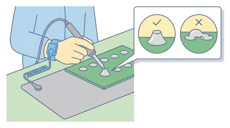
良好なはんだ付け接合部は富士山のような形でなめらかに広がっており、フラックスには金属表面の酸化膜を取り除く役割があります。
A good solder joint spreads smoothly in a Mt. Fuji (cone) shape, and flux removes oxide film from metal surfaces to improve wetting.
隣り合う別の配線のランド同士がはんだでつながってしまう不良を「はんだブリッジ(ブリッジ)」といいます。
A soldering defect where solder accidentally connects adjacent pads of different traces is called a 'solder bridge'.
Key points
- 【×誤り】基板表面に直接はんだ付けするチップ部品を「挿入実装部品」というのは誤り(正しくは「表面実装部品」)。
(× False) Calling small chip components soldered directly onto the PCB surface without holes 'through-hole components' is FALSE (they are surface-mount components). - 【○正しい】アルミ電解コンデンサは極性(+と-)を確認し、良好なはんだ付けは富士山のような形に広がる。
(○ True) Mount aluminum electrolytic capacitors with correct polarity (+ and -), and form smooth Mt. Fuji-shaped solder joints. - 【×誤り】フラックスの役割を「電気的絶縁」としたり、隣りのランドとつながる不良を「部品欠品」というのは誤り(酸化膜除去/ブリッジ)。
(× False) Saying flux electrically insulates joints or calling bridged solder between adjacent pads a 'missing part' is FALSE (flux removes oxide film; connected pads are a solder bridge).
| Word | Meaning |
|---|---|
| プリント基板 | printed circuit board (PCB) |
| 表面実装部品 | surface-mount component (SMD) |
| 極性 | polarity (+ and -) |
| フラックス | flux |
| 酸化膜 | oxide film |
静電気対策・圧着端子・トルクレンチと電気安全
ESD Protection, Crimp Terminals, Torque Wrenches, and Electrical Safety
電子部品を静電気による破損から守るため、作業者はリストストラップを着け、導電性や帯電防止の袋・ケースで保管します。
To protect electronic parts from electrostatic discharge (ESD), wear a grounded wrist strap and store parts in antistatic bags.
電線に圧着端子を取り付けるときは、被覆を適切な長さだけむき、芯線を切り落とさずに専用の圧着工具で確実に圧着します。
When attaching a crimp terminal to a wire, strip the insulation to the proper length without cutting core strands and crimp securely with a dedicated tool.
ねじやボルトを規定の締め付けトルク(強さ)で正確に締めるには「トルクレンチ」を使います。
Use a torque wrench to tighten screws and bolts accurately to the specified tightening torque—neither too tight nor too loose.
過電流が流れたときに溶断して回路を守るのが「ヒューズ」、漏電時に電流を地面に逃がして感電を防ぐのが「アース(接地)」です(被覆が傷ついた電線は絶対に使いません)。
A fuse melts to break the circuit during overcurrent, and grounding (earth) diverts leakage current into the ground to prevent electric shock (never use damaged cords on wet floors).
Key points
- 【×誤り】静電気対策でリストストラップを使わず一般のビニール袋に電子部品を入れるのは誤り。
(× False) Storing electronic components in ordinary plastic bags without wearing a wrist strap for ESD protection is FALSE. - 【○正しい】圧着端子は芯線を切らずに専用工具で圧着し、ねじはトルクレンチで規定トルクに締める。
(○ True) Crimp terminals with a dedicated crimping tool without cutting core wires, and use a torque wrench to tighten bolts to specified torque. - 【○正しい】ヒューズは過電流で溶断して回路を保護し、アース(接地)は漏電時の感電を防ぐ(傷ついた電線をテープ巻きで濡れた床で使うのは×)。
(○ True) Fuses melt on overcurrent to protect circuits, and grounding prevents electric shock during leakage (using a taped damaged wire on a wet floor is FALSE).
| Word | Meaning |
|---|---|
| 静電気 | static electricity (ESD) |
| リストストラップ | wrist strap |
| 圧着端子 | crimp terminal |
| トルクレンチ | torque wrench |
| アース(接地) | grounding (earth) |
Electrical and Electronic Assembly
Practice this chapter in the appOfficial references
- 製造分野特定技能1号評価試験(経済産業省・JAIM) — https://www.jaim-skill.or.jp/exam/about-ssw1/
- 製造分野特定技能評価試験 試験基準(別紙) — https://www.jaim-skill.or.jp/assets/files/exam/top/exam_criteria.pdf