
Building Structures (Structural Systems, Loads, Internal Forces, RC Structures & Foundations)
建築構造(構造方式・荷重と応力・RC構造と基礎)
Rebar Worker Certificate 鉄筋技能士 (Grade 1/2 theory) · 技能検定「鉄筋施工」1級・2級 学科 · Written by Tokutei Pass based on the official study texts; not copied verbatim.
建築構造の分類と各構造の特徴
Classification of Building Structures and Their Characteristics
建築物の骨組みは、用いる主体材料によって「木構造(W造)」「鉄骨構造(S造)」「鉄筋コンクリート構造(RC造)」「鉄骨鉄筋コンクリート構造(SRC造)」などに分類されます。
Building structural frames are classified by primary material into timber structures (W), steel structures (S), reinforced concrete structures (RC), and steel-reinforced concrete structures (SRC).
RC造は鉄筋とコンクリートを一体化させた一体式構造であり、耐火性・耐久性・遮音性・造形の自由度に優れる一方、建物の自重(固定荷重)が大きく工事期間が長い特徴があります。
RC structures are monolithic systems combining reinforcing bars and concrete, offering excellent fire resistance, durability, sound insulation, and freedom of form, though they have heavy self-weight and longer construction periods.
S造は軽くて粘り強く大スパンや高層建築に向きますが、鋼材は熱に弱く約500℃で強度が半減するため「耐火被覆」が必要です。SRC造は鉄骨の周囲に鉄筋とコンクリートを巻き、高い耐震性と「じん性(粘り強さ)」を発揮します。
Steel (S) structures are light and ductile, suited for long spans and high-rises, but steel loses about half its strength at 500°C and requires fireproofing. SRC structures encase structural steel in rebar and concrete, providing superior seismic ductility.
また部材の組み方により、柱と梁の接合部を剛接合にした「ラーメン構造」、柱や梁を設けず耐力壁と床版だけで支える「壁式構造」、三角形の骨組みをピン接合した「トラス構造」に分けられます。
By structural framing system, buildings are categorized into rigid-frame (Rahmen) structures with rigid column-beam joints, wall (box-frame) structures supported by bearing walls and floor slabs, and truss structures composed of pin-connected triangular units.
Key points
- RC造は耐火性・耐久性・遮音性に優れる一体式構造であるが、自重が大きい
RC is a monolithic structure with high fire resistance, durability, and sound insulation, but large dead weight - S造は高温で強度が低下するため耐火被覆が不可欠であり、SRC造は極めて高いじん性(粘り強さ)を持つ
Steel structures require fireproofing against high heat; SRC structures provide exceptional ductility - 柱と梁を剛接合した骨組みを「ラーメン構造」、壁と床で一体に支える方式を「壁式構造」という
Rigid column-beam frames are called Rahmen structures; bearing-wall and slab systems are called wall structures
| Word | Meaning |
|---|---|
| 鉄筋コンクリート構造(RC造) | reinforced concrete structure (RC) |
| 鉄骨鉄筋コンクリート構造(SRC造) | steel-reinforced concrete structure (SRC) |
| ラーメン構造と壁式構造 | rigid-frame (Rahmen) and wall structures |
| じん性(粘り強さ) | ductility / toughness (jinsei) |
鉄筋コンクリート構造が成立する4つの理由
Four Fundamental Reasons Why Reinforced Concrete (RC) Works as a Composite Material
コンクリートは「圧縮力には強いが、引張力には弱い(引張強度は圧縮強度の約10分の1)」という性質を持ちます。逆に鉄筋は引張力に大変強い材料ですが、細長いため圧縮力だけでも座屈しやすい性質があります。
Concrete is strong in compression but weak in tension (its tensile strength is only about 1/10 of its compressive strength). Conversely, steel reinforcing bars have very high tensile strength but, being slender, buckle easily under compression alone.
RC構造が一体として成立する第1の理由は、この2つの材料が互いの弱点を補い、圧縮力を主にコンクリートが、引張力を鉄筋が分担できることです。
The first reason RC succeeds is that the two materials complement each other: concrete primarily resists compressive forces while reinforcing bars placed in tensile zones resist tensile forces.
第2の理由は、異形鉄筋の節とコンクリートの間に強い「付着力」が働き、外力を受けても両者が滑らず一体となって変形・抵抗することです。第3の理由は、常温での「線膨張係数(熱膨張率)」が両者とも約1.0×10のマイナス5乗/℃とほぼ等しいことです。
The second reason is the strong 'bond strength' between deformed bars and concrete, preventing slip under load. The third reason is that both materials have nearly identical 'coefficients of linear thermal expansion' (about 0.00001 /°C), preventing thermal separation.
第4の理由は、強いアルカリ性(pH12〜13程度)のコンクリートが鉄筋の表面に不動態被膜を作って錆び(腐食)を防ぎ、火災時の熱からも鉄筋を守る保護材として働くことです。
The fourth reason is that highly alkaline concrete (pH 12–13) forms a passive film on the steel surface that prevents rusting (corrosion), while concrete cover also insulates the steel from fire heat.
Key points
- コンクリートの引張強度は圧縮強度の約1/10であり、引張側に鉄筋を配置して引張力を負担させる
Concrete tensile strength is about 1/10 of its compressive strength, so steel bars are placed to carry tension - 鉄筋とコンクリートは「線膨張係数(約0.00001/℃)」がほぼ等しく、温度変化で剥離しない
Steel and concrete share nearly the same coefficient of linear thermal expansion (~0.00001 /°C) - 強いアルカリ性のコンクリートが鉄筋の発錆を防ぎ、強い付着力によって一体として挙動する
Strong alkalinity of concrete prevents steel corrosion and strong bond action ensures monolithic behavior
| Word | Meaning |
|---|---|
| 引張強度(圧縮強度の約1/10) | tensile strength (approx. 1/10 of compressive strength) |
| 付着力 | bond strength (fuchakuryoku) |
| 線膨張係数(熱膨張率) | coefficient of linear thermal expansion |
| アルカリ性と不動態被膜 | alkalinity and passive protective film |
建築物に作用する荷重および外力
Loads and External Forces Acting on Buildings
建築物には常時または災害時にさまざまな力が作用します。建築基準法施行令では、これらを「固定荷重」「積載荷重」「積雪荷重」「風圧力」「地震力」などに区分して構造計算を行います。
Buildings are subjected to various permanent and temporary forces. The Building Standards Act Enforcement Order classifies them into dead load, live load, snow load, wind load, and seismic force for structural design.
「固定荷重(死荷重)」とは、柱・梁・床・壁・屋根・仕上げ材など建築物自体の重さです。一方、「積載荷重(活荷重)」とは、建物内の人・家具・物品・車両など移動可能なものの鉛直荷重です。
'Dead load (fixed load)' is the self-weight of the building components themselves, including columns, beams, floors, walls, roofs, and finishes. 'Live load (occupancy load)' is the vertical weight of movable items such as occupants, furniture, goods, and vehicles.
「長期荷重」には常時作用する固定荷重と積載荷重(多雪区域では長期積雪荷重も含む)があり、「短期荷重」には暴風時の風圧力や大地震時の地震力、大雪時の積雪荷重が該当します。
'Long-term loads' include continuously acting dead and live loads, whereas 'short-term loads' include temporary extreme actions such as storm wind pressures, earthquake forces, and heavy snow loads.
風圧力や地震力は主に横方向から作用する「水平力」であり、地震力の大きさは「建物の固定荷重と積載荷重の和」に「地震層せん断力係数」を乗じて求めます。そのため建物が重いほど作用する地震力も大きくなります。
Wind pressure and seismic force act primarily as horizontal lateral forces. Because seismic force is proportional to the building's weight (dead load plus applicable live load) multiplied by the seismic shear coefficient, heavier buildings experience larger seismic forces.
Key points
- 建物自体の自重を「固定荷重(死荷重)」、人や家具・荷物の重さを「積載荷重(活荷重)」という
Self-weight of structural and finish elements is 'dead load'; weight of people and furniture is 'live load' - 固定荷重と積載荷重は鉛直方向の長期荷重、風圧力と地震力は主に水平方向に働く短期外力である
Dead and live loads are vertical long-term loads; wind pressure and seismic force are horizontal short-term forces - 地震力は建物の重量(固定荷重+積載荷重)に比例して大きくなる
Seismic force increases in direct proportion to the total weight of the building
| Word | Meaning |
|---|---|
| 固定荷重(死荷重) | dead load / fixed load (kotei kajū) |
| 積載荷重(活荷重) | live load / occupancy load (sekisai kajū) |
| 積雪荷重・風圧力・地震力 | snow load, wind pressure, and seismic force |
| 長期荷重と短期荷重 | long-term load and short-term load |
力の合成・つり合いとモーメント・偶力の計算
Composition and Equilibrium of Forces, Moments, and Couples
力の性質を決めるには「力の大きさ」「力の向き」「作用点(作用線)」の3つが必要であり、これを「力の三要素」といいます。1点に働く2つの力は「力の平行四辺形の法則」によって1つの合力に合成できます。
Defining a force requires three characteristics known as the 'three elements of a force': magnitude, direction, and point of application (line of action). Two concurrent forces can be combined into a single resultant using the parallelogram law of forces.
例えば1点で直角に交わる水平力3kNと鉛直力4kNが働くとき、合力Rの大きさは三平方の定理より「3の2乗+4の2乗=25」の平方根となり、R=5kNと求められます。
For example, when a horizontal force of 3 kN and a vertical force of 4 kN act perpendicularly at a point, the resultant force R by the Pythagorean theorem is the square root of (3² + 4² = 25), giving R = 5 kN.
ある点Oのまわりで物体を回転させようとする働きを「力のモーメント(M)」といい、力の大きさP(NまたはkN)と、回転中心Oから力の作用線におろした垂直距離L(腕の長さ)の積「M=P×L」で計算します。
The tendency of a force to rotate a body about a point O is called the 'moment of a force (M)' and equals the force P multiplied by the perpendicular distance L (moment arm) from O to the line of action: M = P × L.
また、大きさが等しく向きが反対で平行な2つの力Pが距離Lだけ離れて働く組みを「偶力」といいます。偶力は物体を移動させる合力はゼロで、純粋な回転作用(偶力モーメントM=P×L)だけを生じさせます。
Two parallel forces of equal magnitude P acting in opposite directions at a perpendicular distance L apart form a 'couple (gūryoku).' A couple has zero net translational resultant and produces pure rotation of moment M = P × L regardless of the reference point.
Key points
- 力の三要素は「大きさ・向き・作用点」であり、直交する3kNと4kNの合力は5kNとなる
The three elements of a force are magnitude, direction, and point of application; orthogonal 3 kN and 4 kN forces yield a 5 kN resultant - 力のモーメントは「M=力P×回転中心からの垂直距離L(腕の長さ)」で求め、単位はN・mやkN・mである
Moment M = Force P × Perpendicular arm length L, measured in N·m or kN·m - 大きさが等しく逆向きで平行な2力を「偶力」といい、回転中心の位置にかかわらずM=P×Lとなる
Two equal, opposite, parallel forces form a couple with moment M = P × L
| Word | Meaning |
|---|---|
| 力の三要素(大きさ・向き・作用点) | three elements of a force |
| 力の平行四辺形の法則と合力 | parallelogram law of forces and resultant |
| 力のモーメント(M=P×L) | moment of a force (M = P × L) |
| 偶力と腕の長さ | couple (gūryoku) and moment arm |
部材内部に生じる応力と梁の引張側・圧縮側
Internal Forces in Members and Tensile/Compressive Zones of Beams
外力を受けた部材の内部に働く抵抗力(内力)には、部材軸方向に働く「軸方向力(圧縮力・引張力)」、部材を曲げようとする「曲げモーメント」、断面をずらして切断しようとする「せん断力」の3つがあります。
Under external loads, three internal forces develop within a structural member's cross-section: axial force (compression or tension) along the member axis, bending moment that curves the member, and shear force that tends to slide the section.
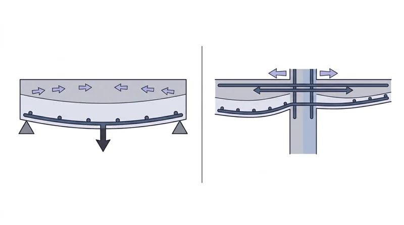
両端を支点で支えた「単純梁」の中央に下向きの集中荷重Pが働くと、梁は下に凸にたわみ、中央部では「上側が圧縮側、下側が引張側」となります。曲げモーメント図は荷重点を頂点とする三角形となります。
In a simply supported beam carrying a downward point load P at midspan, the beam deflects downward so the top is in compression and the bottom is in tension. Its bending moment diagram forms a triangle peaking at midspan.
一方、一端を固定し他端が自由な「片持ち梁(キャンチレバー)」の先端に下向き荷重が働くと、梁全体で「上側が引張側、下側が圧縮側」となり、曲げモーメントは固定端で最大となります。そのため片持ち梁や片持ちスラブでは「上端筋」が主筋として極めて重要です。
Conversely, in a cantilever beam fixed at one end and free at the other under a downward load, the top side is in tension and the bottom side is in compression over its entire length, with maximum bending moment at the fixed support. Thus top bars are critical in cantilevers.
柱と剛接合されたラーメン構造の大梁(両端固定梁・連続梁)では、鉛直荷重時に「中央部では下側が引張側」となり、「両端の柱際(端部)では上側が引張側」となります。そのため梁中央では下端筋を、梁端部では上端筋を多く配筋します。
In a continuous or rigid-frame RC girder under vertical loads, the bottom side is in tension at midspan while the top side is in tension at both column-face ends. Therefore, more bottom main bars are placed at midspan and more top main bars are placed at the beam ends.
Key points
- 断面内力の3要素は「軸方向力(引張・圧縮)」「曲げモーメント」「せん断力」である
The three cross-sectional internal forces are axial force, bending moment, and shear force - 単純梁は下側が引張側となるが、片持ち梁は全長にわたり「上側が引張側」となり固定端で曲げモーメントが最大となる
A simple beam has tension on the bottom, whereas a cantilever beam has tension on the top with maximum moment at the fixed end - 連続梁やラーメンの大梁では「中央部は下側が引張」「両端部(柱際)は上側が引張」となる
In rigid-frame girders, tension occurs at the bottom at midspan and at the top at both beam ends
| Word | Meaning |
|---|---|
| 軸方向力・曲げモーメント・せん断力 | axial force, bending moment, and shear force |
| 単純梁と片持ち梁 | simply supported beam and cantilever beam |
| 引張側と圧縮側 | tensile zone and compressive zone |
| 固定端と中央部 | fixed support end and midspan region |
RC部材の破壊性状とせん断補強筋の役割
Failure Modes of RC Members and the Role of Shear Reinforcement
RC造の柱や梁が地震時に大きな力を受けたときの破壊形式には、主筋が降伏して粘り強く変形する「曲げ破壊(延性破壊)」と、斜めひび割れが生じて急激に耐力を失う「せん断破壊(ぜい性破壊)」があります。
When RC columns and beams experience severe earthquake forces, two main failure modes exist: ductile flexural failure, where main bars yield and deform gradually, and brittle shear failure, where diagonal cracks cause sudden loss of load capacity.
せん断破壊や主筋に沿ってコンクリートが割れる「付着割裂破壊」が起きると、建物が一瞬で倒壊する危険があります。そのため耐震設計では、せん断破壊を防いで曲げ降伏を先行させることが大原則です。
If brittle shear failure or bond-splitting failure occurs along the main bars, the structure can collapse abruptly. Therefore, seismic design prioritizes preventing shear failure so that ductile flexural yielding governs.
柱の主筋周囲に巻く「帯筋(フープ)」および梁の主筋周囲に巻く「あばら筋(スターラップ)」は、斜め方向のせん断ひび割れの拡大を防ぎ、せん断耐力と変形能力(じん性)を高める重要な役割を担います。
Column hoops (obikin) and beam stirrups (abarakin) wrapped around the main bars restrain diagonal shear cracks, greatly enhancing shear capacity and deformation ductility (jinsei).
さらに帯筋やあばら筋は、内部のコアコンクリートを周囲から拘束して圧縮靭性を高めるとともに、圧縮力を受ける主筋が外側へはらみ出す「座屈」を抑え、主筋位置を正確に保持する働きもあります。
In addition, hoops and stirrups confine the core concrete to improve compressive toughness, prevent outward buckling of compressed main bars, and hold the longitudinal bars accurately in position.
Key points
- 急激に壊れる「せん断破壊(ぜい性破壊)」を防ぎ、粘り強い「曲げ破壊(延性破壊)」を先行させる設計とする
Seismic design prevents sudden brittle shear failure and ensures ductile flexural yielding - 柱の「帯筋(フープ)」と梁の「あばら筋(スターラップ)」は、せん断破壊を防止し部材のじん性を高める
Column hoops (obikin) and beam stirrups (abarakin) resist shear failure and increase member ductility - 帯筋・あばら筋には、内部コンクリートの拘束と圧縮主筋の「座屈防止」の役割もある
Hoops and stirrups also confine core concrete and prevent buckling of longitudinal main bars
| Word | Meaning |
|---|---|
| せん断破壊(ぜい性破壊)と曲げ破壊 | shear failure (brittle failure) and flexural failure |
| 付着割裂破壊 | bond-splitting failure (fuchaku katsuretsu hakai) |
| 帯筋(フープ)とあばら筋(スターラップ) | column hoops (obikin) and beam stirrups (abarakin) |
| 主筋の座屈防止 | prevention of main bar buckling |
基礎構造の種類(直接基礎・杭基礎)と地盤
Foundation Types (Shallow Foundations and Pile Foundations) and Soil Behavior
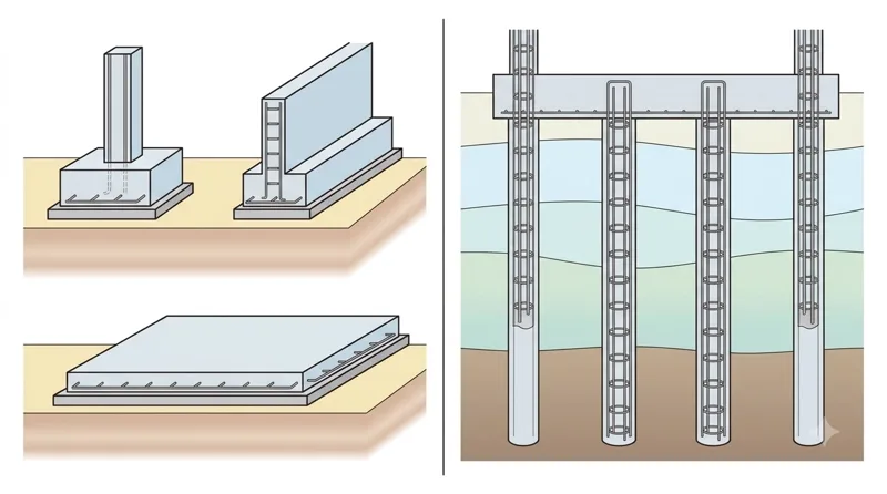
建物の荷重を地盤へ安全に伝える下部構造を「基礎」といい、支持形式によって浅い良質地盤に直接支える「直接基礎」と、深い支持層まで杭を打ち込む「杭基礎」に大別されます。
Foundations safely transfer building loads to the ground and are broadly classified into shallow (direct) foundations resting directly on firm near-surface soil, and pile foundations transferring loads through piles to deeper strata.
直接基礎には、柱1本ごとに設ける「独立フーチング基礎」、壁や柱列の下に連続させる「布基礎(連続フーチング基礎)」、建物下部全面を厚い床版で支える「べた基礎(マットスラブ基礎)」があります。
Shallow foundations include isolated footings under individual columns, strip (continuous) footings under walls or column rows, and mat (raft) foundations supporting the entire building footprint on a thick slab.
杭基礎は、杭先端を硬い支持地盤に到達させて支える「支持杭」と、杭周面と土との摩擦力で支える「摩擦杭」に分けられます。また施工法により、工場製品の「既製杭(PC杭・PHC杭・鋼管杭)」と、現場で掘削した孔に鉄筋かごを建て込んでコンクリートを打つ「場所打ちコンクリート杭(アースドリル工法等)」があります。
Pile foundations are classified by load support into end-bearing piles reaching a hard bearing stratum and friction piles relying on skin friction. By installation method, they include precast piles (PHC, steel pipe) and cast-in-place concrete piles (such as the earth-drill method) where a rebar cage is lowered into a bored hole.
なお、ゆるい砂質地盤で地下水位が高い場所では、大地震時の振動によって砂粒子の間の間隙水圧が急上昇し、地盤が液体状になって建物が沈下・傾斜する「液状化現象」が起きやすいため注意が必要です。
In loose, saturated sandy soils with a high groundwater table, earthquake shaking sharply increases pore-water pressure, causing the ground to behave like a liquid in a phenomenon known as 'soil liquefaction (ekijōka).'
Key points
- 直接基礎には「独立フーチング基礎」「布基礎」「べた基礎」があり、1種類の基礎形式に統一して不同沈下を防ぐ
Shallow foundations include isolated, strip, and mat footings; foundation types should not be mixed in one building to avoid differential settlement - 杭基礎には支持機構による「支持杭・摩擦杭」と、施工法による「既製杭・場所打ちコンクリート杭」がある
Pile foundations are categorized into end-bearing vs. friction piles, and precast vs. cast-in-place concrete piles - 地下水位が高くゆるい砂質土層では、地震時に地盤が泥水状となる「液状化現象」が発生しやすい
Loose saturated sandy ground is prone to soil liquefaction during earthquakes
| Word | Meaning |
|---|---|
| 直接基礎(独立・布・べた基礎) | shallow foundations (isolated, strip, and mat) |
| 杭基礎(支持杭と摩擦杭) | pile foundations (end-bearing and friction piles) |
| 場所打ちコンクリート杭(アースドリル工法) | cast-in-place concrete piles (earth-drill method) |
| 砂質地盤の液状化現象 | soil liquefaction in sandy ground |
他構造(鉄骨造・木造・組積造)と屋根形状の基礎知識
Basics of Steel, Timber, Masonry Structures, and Roof Shapes
技能検定の建築構造科目では、RC造以外の一般建築構造も出題されます。鉄骨構造(S造)の接合方法には「高力ボルト接合」「溶接接合」「普通ボルト接合」があり、高力ボルト摩擦接合は強く締め付けた鋼板接触面の摩擦力で応力を伝えます。
The Building Structure subject in the Skill Test also covers non-RC structures. In steel structures (S), joints use high-strength bolts, welding, or ordinary bolts; high-strength bolt friction connections transmit forces via friction between tightly clamped steel contact surfaces.
またS造の柱脚やトラスの節点などで、斜材(ブレース)や梁を取り付けるために用いる連結用鋼板を「ガセットプレート」といい、H形鋼の断面は上下の水平板である「フランジ」と中央の縦板である「ウェブ」で構成されます。
The connecting steel plate used to attach braces or beams at steel joints is called a 'gusset plate.' An H-section steel member consists of top and bottom horizontal plates called 'flanges' and a central vertical plate called the 'web.'
木構造(在来軸組工法)では、柱と横架材(土台・胴差し・桁)で囲まれた鉛直構面に斜め材の「筋かい」を入れて地震や風の水平力に抵抗させ、床組みや小屋組みの水平構面の隅角部には「火打ち材」を斜めに設けて変形を防ぎます。
In traditional timber post-and-beam framing, diagonal braces installed in vertical wall planes to resist wind and earthquake forces are called 'sujikai' (wall braces), whereas diagonal members stiffening the corners of horizontal floor or roof planes are called 'hiuchizai' (angle ties).
屋根の形状では、棟から2方向へ流れる「切りづま屋根」、大棟と4本の隅棟をもち4方向へ流れる「寄棟屋根」、1方向のみに傾斜する「片流れ屋根」などを区別します。また補強コンクリートブロック造では空洞部に縦筋を通しモルタルやコンクリートを充填して補強します。
Common roof shapes include the gable roof (kirizuma) sloping in two directions, the hip roof (yosemune) sloping in four directions with four hip ridges, and the shed roof (katanagare) sloping in one direction. Reinforced concrete block masonry is strengthened by inserting vertical rebars into hollow cores and grouting them with mortar or concrete.
Key points
- H形鋼の上下板を「フランジ」、中央縦板を「ウェブ」といい、高力ボルト摩擦接合は材間の摩擦力で力を伝える
The top/bottom plates of an H-section are 'flanges' and the vertical middle plate is the 'web'; high-strength bolt friction joints transfer force by friction - 木造軸組工法では、壁面の斜め材を「筋かい」、水平面の隅角部の斜め材を「火打ち材」という
In timber framing, diagonal wall braces are 'sujikai' and horizontal corner braces are 'hiuchizai' - 屋根形状は2方向流れの「切りづま屋根」と、4方向へ流れる「寄棟屋根」を正確に見分ける
Distinguish clearly between a two-way sloping gable roof (kirizuma) and a four-way sloping hip roof (yosemune)
| Word | Meaning |
|---|---|
| 高力ボルト摩擦接合とガセットプレート | high-strength bolt friction connection and gusset plate |
| H形鋼のフランジとウェブ | flange and web of H-section steel |
| 木造の筋かいと火打ち材 | timber wall brace (sujikai) and horizontal corner brace (hiuchizai) |
| 切りづま屋根と寄棟屋根 | gable roof (kirizuma) and hip roof (yosemune) |
Building Structures
Practice this chapter in the appOfficial references
- 建築基準法施行令 第3章 構造強度(e-Gov法令検索) — https://laws.e-gov.go.jp/law/325CO0000000338
- 鉄筋施工技能検定 試験科目及びその範囲並びにその細目(厚生労働省) — https://www.mhlw.go.jp/stf/seisakunitsuite/bunya/koyou_roudou/jinzaikaihatsu/ability_skill/ginoukentei/index.html