
Construction Methods (Fabrication, Placing, Anchorage & Splices, Gas Pressure Welding, Scheduling)
施工法(加工・配筋・定着と継手・圧接・工程管理)
Rebar Worker Certificate 鉄筋技能士 (Grade 1/2 theory) · 技能検定「鉄筋施工」1級・2級 学科 · Written by Tokutei Pass based on the official study texts; not copied verbatim.
鉄筋の切断・曲げ加工の原則とフック・許容差
Principles of Cutting and Bending Rebar, Hook Standards, and Tolerances
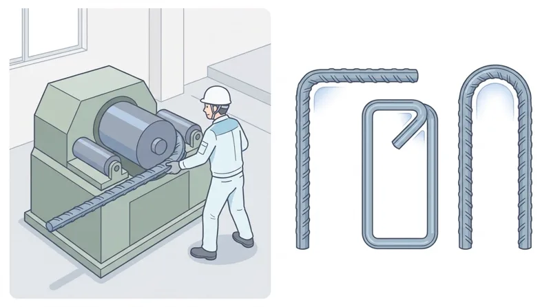
鉄筋の切断には電動切断機(バーカッター)を用い、刃の奥深くに鉄筋を入れて当て具で直角に保って切断します。ガス圧接用の鉄筋端面は、切断機でせん断したままにせず、直角かつ平滑に仕上げます。
When cutting reinforcing bars with an electric bar cutter, place the bar deep between the blades and hold it perpendicular using the backstop. Bar ends intended for gas pressure welding must be cut square and smooth rather than left with sheared burrs.
鉄筋の折り曲げ加工は、加熱すると材質が変化して強度が低下するため、常温で行う「冷間加工」を原則とし、一度曲げた鉄筋の「曲げ戻し」は行ってはなりません。また加工寸法の許容差は一般に「±5mm」です。
Bending must be performed at ambient temperature ('cold bending') because heating alters steel properties; re-straightening a bent bar is prohibited. The standard fabrication dimensional tolerance for general stirrups, hoops, and bent bars is '±5 mm.'
異形鉄筋(SD295・SD345)の末端フック(90°・135°・180°)の曲げ内法直径は、D16以下で「3d以上」、D19〜D25で「4d以上」、D29〜D41で「5d以上」とします。柱主筋・梁主筋の90°折り曲げ定着部はD25以下で4d以上です。
For deformed bars (SD295, SD345), the minimum inside bend diameter of end hooks (90°, 135°, 180°) is '3d or more' for D16 and smaller, '4d or more' for D19–D25, and '5d or more' for D29–D41. For 90° anchorage bends of column/beam main bars of D25 or smaller, it is at least 4d.
フックの直線余長は、曲げ終点から「180°フックで4d以上」「135°フックで6d以上(帯筋・あばら筋は6d以上かつ60mmまたは8d以上)」「90°フックで8d以上(柱・梁主筋の出隅定着は12d以上)」を確保します。
The straight tail extension beyond the bend is 'at least 4d for a 180° hook,' 'at least 6d for a 135° hook,' and 'at least 8d for a 90° hook (or 12d for 90° anchorage hooks on column and beam main bars).'
Key points
- 鉄筋の曲げ加工は常温の「冷間加工」を原則とし、曲げ戻しは禁止であり、加工寸法の許容差は「±5mm」である
Rebar bending must be done by cold working, re-bending is prohibited, and the standard fabrication tolerance is ±5 mm - SD295・SD345のフック曲げ内法直径は、D16以下=3d以上、D19〜D25=4d以上、D29以上=5d以上とする
Minimum inside bend diameters for SD295/SD345 hooks: D16 or smaller ≥ 3d, D19–D25 ≥ 4d, D29 or larger ≥ 5d - フックの余長は「180°フック=4d以上」「135°フック=6d以上」「90°フック=8d以上(柱・梁主筋は12d以上)」とする
Hook tail lengths: 180° hook ≥ 4d, 135° hook ≥ 6d, 90° hook ≥ 8d (12d for column/beam main bar 90° anchorage)
| Word | Meaning |
|---|---|
| 冷間加工と曲げ戻し禁止 | cold working and prohibition of re-bending |
| 加工寸法の許容差(±5mm) | fabrication dimensional tolerance (±5 mm) |
| 曲げ内法直径(3d・4d・5d) | inside bend diameter (3d, 4d, 5d) |
| フックの余長(4d・6d・8d・12d) | hook tail extension (4d, 6d, 8d, 12d) |
鉄筋相互の「あき」と「かぶり厚さ」およびスペーサーの配置
Clear Spacing Between Bars, Concrete Cover, and Spacer Placement
並行する鉄筋同士の表面間の最短距離(内法寸法)を「鉄筋のあき」といいます。打ち込んだコンクリートが隅々まで行き渡り、じゃんか(豆板)を防いで付着力を確保するために十分なあきが必要です。
The minimum clear surface-to-surface distance between parallel reinforcing bars is called 'clear spacing (aki).' Adequate clear spacing is essential so fresh concrete flows around every bar without honeycombing and develops full bond.
柱および梁の主筋間の「あき」の最小値は、公共建築工事標準仕様書およびJASS 5により、「① 25mm以上」「② 呼び名の数値(公称直径d)の1.5倍以上」「③ 粗骨材最大寸法の1.25倍以上」の3つのうち最も大きい値以上とします。
Under the Public Building Standard Specifications and JASS 5, the minimum clear spacing between main bars in columns and beams is the greatest of: (1) 25 mm, (2) 1.5 times the nominal bar diameter d, and (3) 1.25 times the maximum coarse aggregate size.
「かぶり厚さ」は最外縁の鉄筋表面からコンクリート表面までの最短距離です。施工誤差を見込み、建築基準法施行令第79条の最小かぶり厚さ(20・30・40・60mm)に「10mm」を加えた「設計かぶり厚さ」を確保します。
'Concrete cover (kaburi atsusa)' is the shortest distance from the outer surface of the outermost bar to the concrete surface. Design cover adds a 10 mm construction margin to the statutory minimum cover (20, 30, 40, or 60 mm) specified in Article 79 of the Enforcement Order.
スペーサーは、基礎や大梁の下端には「コンクリート製または鋼製」を中間1.5m程度の間隔で置き、床・屋根スラブには「0.9m程度」の間隔、壁筋や柱帯筋の側面には「ドーナツ型プラスチック製」を用います。
Under Table 5.3.7 of the Public Building Standard Specifications, concrete/mortar block spacers or rust-proofed steel spacers are placed under foundations and beam bottoms near the ends and at about 1.5 m intervals in the span; floor and roof slabs (top and bottom bars) use a standard spacer spacing of 'about 0.9 m,' while donut-type plastic spacers are clipped onto wall bars and column hoops.
Key points
- 鉄筋の「あき」は「25mm」「公称直径の1.5倍」「粗骨材最大寸法の1.25倍」のうち最大の値以上とする
Minimum clear bar spacing is the largest of 25 mm, 1.5d, and 1.25 times the maximum coarse aggregate size - 公共建築工事標準仕様書表5.3.7により、梁下端は中間1.5m程度、床スラブは「0.9m程度」の間隔でスペーサーを置く
Under Table 5.3.7 of the Public Building Standard Specifications, beam bottom spacers are placed near the ends and at ~1.5 m intervals, while floor slab spacers are placed at '~0.9 m' intervals - 壁の縦横筋や柱帯筋など側面型枠とのかぶり保持には「ドーナツ型プラスチック製スペーサー」を用いる
Use donut-type plastic spacers on wall bars and column hoops to maintain side formwork cover
| Word | Meaning |
|---|---|
| 鉄筋のあき(25mm・1.5d・粗骨材の1.25倍) | clear spacing between bars (25 mm, 1.5d, 1.25x max aggregate) |
| 設計かぶり厚さと最小かぶり厚さ | design concrete cover and minimum concrete cover |
| コンクリート製・鋼製スペーサー | concrete spacers and steel spacers |
| ドーナツ型プラスチック製スペーサー | donut-type plastic spacers |
鉄筋の定着長さと重ね継手の基準
Standards for Development (Anchorage) Length and Lap Splices
部材の応力を接合先の部材へ確実に伝えるために鉄筋を埋め込む長さを「定着長さ」といい、鉄筋の鋼種(SD295・SD345・SD390等)とコンクリートの設計基準強度(Fc)によって「直線定着長さL1」と「フック付き定着長さL2」が定められます。
The embedment length required to transfer stress safely into a supporting member is the 'development (anchorage) length,' specified as straight anchorage length L1 or hooked anchorage length L2 according to steel grade and specified concrete strength Fc.
鉄筋強度が高いほど定着長さは長くなり、コンクリート強度(Fc)が高いほど短くなります。公共建築工事標準仕様書表5.3.4では、普通コンクリートFc21にSD345を定着する場合、直線定着L1=「45d以上」、フック付き定着L2=「35d以上」です。
Higher-yield-strength steel requires a longer anchorage or splice length, whereas higher concrete strength Fc shortens the required length. Under Table 5.3.4 of the Public Building Standard Specifications, for general deformed bar SD345 in normal-weight concrete of Fc21, the straight anchorage length L1 is '45d or more' and the hooked anchorage length L2 is '35d or more' (for SD295A in Fc21, L1 = 40d and L2 = 30d).
大梁主筋を柱に90°折り曲げ定着する場合、柱面から折り曲げ外端までの「水平投影定着長さ」は「柱せいの3/4(0.75倍)以上」とします。また一般床スラブや屋根スラブの下端筋を梁に直線定着する長さは「10d以上かつ150mm以上」です。
When main girder bars are anchored with a 90° bend into a column, the 'horizontal projected anchorage length' from the column face to the outer edge of the bend must be at least 3/4 (0.75) of the column depth. Bottom bars of general floor and roof slabs anchored straight into beams require at least '10d and 150 mm.'
2本の鉄筋を重ねて結束する「重ね継手」は、応力の小さい位置に設け、隣り合う継手位置をずらす「千鳥配置」とします。なお、呼び名に「D35」以上(D35・D38・D41)の太径鉄筋は、付着割裂のおそれがあるため原則として重ね継手を用いず、ガス圧接や機械式継手とします。
Lap splices are placed in regions of low stress and staggered across adjacent bars. Reinforcing bars of 'D35 or larger' (D35, D38, D41) must not use lap splices in principle; gas pressure welding or mechanical couplers are used instead.
Key points
- 公共建築工事標準仕様書表5.3.4において、普通コンクリートFc21・SD345の直線定着長さL1は「45d以上」(L2は35d以上)である
Under Table 5.3.4 of the Public Building Standard Specifications, straight anchorage length L1 for SD345 in Fc21 normal concrete is '45d or more' (hooked L2 is 35d or more) - 大梁主筋の柱への水平投影定着長さは「柱せいの3/4(0.75D)以上」、床スラブ下端筋の梁定着長さは「10d以上かつ150mm以上」
Projected anchorage of girder main bars into columns ≥ 3/4 column depth; slab bottom bar anchorage into beams ≥ 10d and ≥ 150 mm - 「D35以上」の太径鉄筋には原則として重ね継手を用いず、腹筋の重ね継手長さは「150mm程度」とする
Lap splices are prohibited in principle for bars D35 and larger; beam side-face bars (harakin) have a lap length of about 150 mm
| Word | Meaning |
|---|---|
| 直線定着長さL1とフック付き定着長さL2 | straight anchorage length L1 and hooked anchorage length L2 |
| 水平投影定着長さ(柱せいの3/4以上) | horizontal projected anchorage length (≥ 3/4 column depth) |
| スラブ下端筋の定着(10d以上かつ150mm以上) | slab bottom bar anchorage (≥ 10d and ≥ 150 mm) |
| D35以上の重ね継手原則禁止 | prohibition of lap splices for D35 and larger |
基礎・基礎梁の配筋施工と人通孔補強
Reinforcement Placing for Foundations, Foundation Beams, and Access Openings
独立フーチング基礎のベース筋は、地盤反力によって下側が引張側となるため下端に格子状に配筋します。長方形の独立基礎底盤では、曲げモーメントが大きい「長辺方向」の鉄筋を下側(外側)に、短辺方向を上側に組みます。
Base bars of an isolated footing resist upward soil bearing pressure, placing the bottom face in tension. In a rectangular isolated footing, the bars in the 'long-side direction' carry a larger bending moment and are placed on the bottom (outer) layer, with the short-side bars on top of them.
一方、杭基礎のフーチング(パイルキャップ)では、杭頭をフーチング下端から「100mm程度」飲み込ませ、ベース筋は「杭頭の上部」を通して配筋します。また捨てコンクリート上では基礎の最小かぶり厚さ60mm以上(設計70mm程度)を確保します。
In a pile cap footing, pile heads are embedded about 100 mm into the bottom of the footing, and the footing base bars are placed directly 'above the pile heads.' Over blinding concrete, a minimum cover of at least 60 mm (about 70 mm design cover) is maintained.
基礎梁(地中梁・FG)は、上部構造の荷重と地盤反力を受ける重要な梁であり、主筋・あばら筋のほか、梁せいが高いため側面に「腹筋」およびあばら筋のはらみ出しを防ぐ「幅止め筋」を配置します。腹筋の重ね継手長さは「150mm程度」です。
Foundation beams (grade beams, FG) have deep sections, so in addition to main bars and stirrups, side-face bars (harakin) and cross-ties (habadomekin) are installed. The standard lap splice length for side-face bars (harakin) is 'about 150 mm.'
基礎梁に点検用の「人通孔(貫通孔)」を設ける場合は、応力集中による斜めひび割れやせん断破壊を防ぐため、孔の上下・左右および四隅の斜め方向に専用の「貫通孔補強筋」を必ず配置します。
Where inspection access holes (jintsūkō) or sleeve penetrations pass through a foundation beam, dedicated opening reinforcement (top, bottom, vertical, and diagonal corner bars) must be installed around the opening to prevent shear cracking.
Key points
- 長方形の独立基礎底盤では、下側に「長辺方向」のベース筋を配置し、杭基礎では杭頭の上部にベース筋を通す
In a rectangular isolated footing, long-direction base bars go on the bottom; in pile caps, base bars pass above the pile heads - 基礎梁の側面に設ける「腹筋」の重ね継手長さは「150mm程度」とし、「幅止め筋」であばら筋の変形を防ぐ
Side-face bars (harakin) use a lap splice length of about 150 mm, and cross-ties (habadomekin) prevent stirrup bulging - 基礎梁の「人通孔(開口部)」の周囲には、斜め補強筋等の専用補強筋を配置する
Access openings (jintsūkō) in foundation beams require dedicated diagonal and perimeter reinforcement
| Word | Meaning |
|---|---|
| 独立フーチング基礎のベース筋 | base reinforcement of isolated footing |
| 杭頭の飲み込みとパイルキャップ | pile head embedment and pile cap |
| 腹筋と幅止め筋 | side-face bar (harakin) and cross-tie (habadomekin) |
| 基礎梁の人通孔(貫通孔)補強 | access opening (jintsūkō) reinforcement in foundation beams |
柱・梁の配筋施工(交差部・二段筋・スパイラル筋)
Column and Beam Reinforcement (Joints, Two-Layer Bars, and Spiral Hoops)
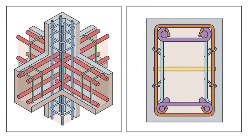
柱では四隅を含む柱主筋の周囲に「帯筋(フープ)」を所定のピッチで巻き、フックは135°以上に曲げて柱内部のコアコンクリートに定着します。また「スパイラル筋(らせん鉄筋)」の重ね継手は「1.5巻き以上かつ300mm以上」とし、上下端には1.5巻き以上の添え巻きを設けます。
In columns, hoops (obikin) wrap around the longitudinal column bars with 135° hooks anchored into the core concrete. For spiral reinforcement, lap splices must be at least 1.5 turns and at least 300 mm long, with 1.5 extra finishing turns at both top and bottom ends.
柱と大梁の交差部(仕口部)では、「柱主筋を最外側(帯筋の内側)に通し、大梁主筋はその内側に通す」のが鉄則です。また大梁どうしが直交する交差部では、片方の大梁上端筋の下に他方の大梁上端筋をくぐらせてかぶり厚さを守ります。
At column-girder joints, the strict rule is that girder main bars pass inside the column main bars. Where two main girders intersect at right angles, the top bars of one girder pass beneath the top bars of the other girder so slab cover is not reduced.
大梁と小梁が交差する部分では、小梁の荷重を大梁に支持させるため、「小梁の上端主筋は大梁の上端主筋の上に乗せて掛け、小梁の下端主筋も大梁の下端主筋(または腹筋)の上に通して定着」します。
Where a secondary beam (B) frames into a main girder (G), the secondary beam is supported by the main girder, so the top main bars of the secondary beam must rest on top of the top main bars of the main girder.
梁主筋を2段に配置する「二段筋」では、1段目と2段目の主筋間に「まくら筋(スペーサー筋)」を挟んで所定のあきを保ちます。また梁端の上端二段筋を途中で止める「カットオフ筋」は、構造図で定められた柱面からの長さ(内法スパンの1/4や1/6+余長等)を正確に守ります。
When beam main bars are placed in two layers (nidankin), spacer bars (makurakin) are inserted between the first and second layers to maintain clear spacing. Cut-off bars terminated partway into the span must strictly follow the specified cutoff lengths (such as l0/4 or l0/6 plus anchorage extension) from the column face.
Key points
- スパイラル筋の重ね継手は「1.5巻き以上かつ300mm以上」とし、末端には1.5巻き以上の添え巻きを設ける
Spiral reinforcement lap splices require at least 1.5 turns and 300 mm, plus 1.5 extra turns at ends - 柱梁仕口部では「大梁主筋は柱主筋の内側」に通し、小梁主筋は「大梁主筋の上」に乗せて定着する
Girder main bars pass inside column main bars; secondary beam main bars rest on top of main girder main bars - 梁の1段目主筋と2段目主筋の間には「まくら筋」を入れて鉄筋のあきを確保する
Spacer bars (makurakin) are placed between first-layer and second-layer beam main bars
| Word | Meaning |
|---|---|
| スパイラル筋(1.5巻き以上かつ300mm以上) | spiral reinforcement (≥ 1.5 turns and ≥ 300 mm) |
| 柱梁仕口部と大梁・小梁交差部 | column-girder joint and girder-beam intersection |
| 二段筋とまくら筋 | second-layer bars (nidankin) and spacer bars (makurakin) |
| カットオフ筋と折り曲げ筋 | cut-off bars and bent-up bars |
床スラブ・壁・階段の配筋と開口部補強
Reinforcement for Floor Slabs, Walls, Stairs, and Openings
長方形の四辺固定床スラブでは、曲げモーメントが大きくなる「短辺方向」を主筋、「長辺方向」を配力筋とします。したがつて下端筋では短辺方向の主筋を一番下(外側)に、上端筋では短辺方向の主筋を一番上(外側)に配置します。
In a rectangular two-way slab supported on four sides, the 'short-span direction' experiences larger bending moments and serves as the main reinforcement, while the 'long-span direction' serves as distribution reinforcement. Thus short-span main bars are placed on the outermost layers (bottom-most in the lower mat, top-most in the upper mat).
スラブ筋を1本おきに折り曲げて上端と下端を交互に配筋する方式を「千鳥配筋」といいます。スラブ周囲の出隅部や片持ちスラブには温度収縮やひび割れを防ぐ補強筋を入れ、上端筋の高さ保持にはバーチェア(馬スペーサー)を用います。
Alternating straight bars and bent-up bars every other pitch is called 'staggered arrangement (chidori haikin).' Bar chairs (high chairs) are placed to support the upper slab reinforcement mat at the correct depth.
RC壁には鉄筋を1列に組む「シングル配筋」と2列に組む「ダブル配筋(複配筋)」があり、ダブル配筋では2列の鉄筋網の間隔を保つ「幅止め筋」を配置します。一般の壁では外側(型枠側)に誘発目地等のひび割れ抑制も考慮して指定通りに縦筋・横筋を組みます。
RC walls are reinforced with either a single layer ('single reinforcement') or two layers ('double reinforcement'); in double-reinforced walls, cross-ties (habadomekin) are installed to maintain the spacing between the two mats.
壁や床スラブに窓・出入口・設備用の開口部を設ける場合は、切断される鉄筋と同量以上の補強筋を周囲に添えるとともに、開口四隅のひび割れを防ぐ「斜め補強筋」を配置します。壁開口部補強筋には標準として「D13以上」の異形鉄筋を用います。
Around window, door, or duct openings in walls and slabs, perimeter trimming bars and 45° diagonal corner bars must be placed to prevent corner cracking. Wall opening reinforcement uses deformed bars of 'D13 or larger' as standard.
Key points
- 長方形床スラブは「短辺方向が主筋・長辺方向が配力筋」であり、短辺方向主筋を外側(下筋は下側、上筋は上側)に配置する
In rectangular slabs, short-span bars are main bars and placed on the outer layers (bottom of lower mat, top of upper mat) - ダブル配筋(複配筋)の壁では、2列の鉄筋網の間隔を保持するために「幅止め筋」を設ける
Double-reinforced walls require cross-ties (habadomekin) to hold the two reinforcement curtains apart - 壁やスラブの開口部周囲および四隅の斜め方向には、ひび割れ防止のため「D13以上」の開口部補強筋を配置する
Wall openings require vertical, horizontal, and diagonal corner trimming bars of 'D13 or larger'
| Word | Meaning |
|---|---|
| 短辺方向(主筋)と長辺方向(配力筋) | short-span direction (main bars) and long-span direction (distribution bars) |
| 千鳥配筋とバーチェア | staggered bar arrangement (chidori haikin) and bar chairs |
| シングル配筋とダブル配筋(複配筋) | single reinforcement and double reinforcement |
| 開口部補強筋(四隅の斜め筋・D13以上) | opening trimming reinforcement (diagonal corner bars, D13 or larger) |
ガス圧接継手の施工方法と外観・超音波検査基準
Gas Pressure Welding Execution and Visual / Ultrasonic Inspection Standards
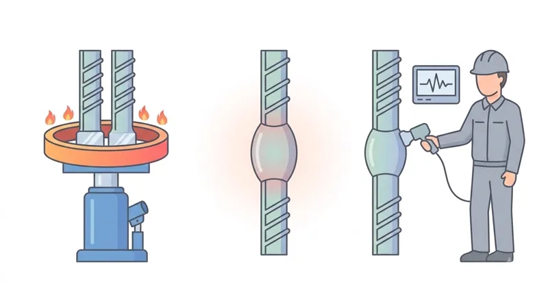
「ガス圧接継手」は、突き合わせた鉄筋端面に油圧ポンプで軸方向の圧力を加えながら酸素・アセチレン炎で1200〜1300℃程度に加熱し、端面を溶かさずに接合する固相接合です。施工には「ガス溶接技能講習」と圧接技量資格が必要です。
Gas pressure welding is a solid-state joining method in which the ends of two rebars are pressed together axially by a hydraulic ram while heated to about 1200–1300°C with an oxy-acetylene ring burner without melting. Operators require both a Gas Welding Skill Training certificate and a pressure-welding qualification.
圧接前に鉄筋端面をグラインダー等で直角・平滑に研削し、突き合わせたときの端面間のすき間は「2mm以下」とします。加熱初期は端面の酸化を防ぐためアセチレン過多の「還元炎」で隙間が閉じるまで加熱し、その後「中性炎」で圧接部全体を加熱します。
Before welding, bar ends are ground flat and square so the gap between butted faces is '2 mm or less.' Initial heating uses an acetylene-rich 'reducing (carburizing) flame' until the gap closes to prevent oxidation, followed by a 'neutral flame' to heat the joint uniformly.
正常な圧接部のふくらみ基準は、①ふくらみの直径が「鉄筋径dの1.4倍以上」、②ふくらみの長さが「1.1d以上」、③圧接面とふくらみ頂部のずれが「1/4d以下」、④鉄筋軸の偏心量(軸ずれ)が「1/5d(0.2d)以下」、⑤折れ曲がり角度が「2°以下」です(異径圧接は細い方の径dで判定)。
Acceptance standards for the upset bulge are: (1) bulge diameter 'at least 1.4d,' (2) bulge length 'at least 1.1d,' (3) offset of bulge peak from weld plane '1/4d or less,' (4) axial eccentricity '1/5d (0.2d) or less,' and (5) angular bend '2° or less' (using the smaller bar diameter d for different-size bars).
検査では「全数外観検査」とロットごとの「超音波探傷検査(または引張試験)」を行います。わずかな偏心超過やふくらみ不足は「再加熱修正」できますが、著しい焼け・割れ・過大な偏心がある場合は圧接部を切り取って再圧接します。
Inspection consists of 100% visual inspection of all joints plus lot-based ultrasonic testing (or tensile testing). Minor insufficient bulge can be reheated and re-upset, but joints with cracking, burning, or severe eccentricity must be cut out and re-welded.
Key points
- ガス圧接前の端面すき間は「2mm以下」とし、初期は「還元炎」、隙間閉塞後は「中性炎」で加熱する
End gap before welding must be 2 mm or less; heat initially with a reducing flame and then with a neutral flame after gap closure - 圧接部のふくらみは「直径1.4d以上・長さ1.1d以上」、軸の偏心量は「1/5d以下」、頂部のずれは「1/4d以下」とする
Weld bulge diameter ≥ 1.4d, length ≥ 1.1d, axial eccentricity ≤ 1/5d, and peak offset ≤ 1/4d - 全数外観検査と抜取りの超音波探傷検査を行い、著しい欠陥(割れ・焼け等)は切断して再圧接する
Perform 100% visual inspection and sampling ultrasonic testing; cut out and re-weld joints with cracks or severe burning
| Word | Meaning |
|---|---|
| 端面のすき間(2mm以下)と還元炎・中性炎 | end face gap (≤ 2 mm), reducing flame, and neutral flame |
| ふくらみの直径(1.4d以上)と長さ(1.1d以上) | bulge diameter (≥ 1.4d) and bulge length (≥ 1.1d) |
| 軸の偏心量(1/5d以下)と頂部のずれ(1/4d以下) | axial eccentricity (≤ 1/5d) and peak offset (≤ 1/4d) |
| 全数外観検査と超音波探傷検査 | 100% visual inspection and ultrasonic flaw detection |
機械式継手・溶接継手・先組み工法と配筋検査
Mechanical Splices, Prefabricated Cage Construction, and Rebar Inspection
「機械式継手」は、カプラー(筒状接続子)を用いて鉄筋を機械的に接合する工法で、天候に左右されず太径鉄筋や高強度鉄筋にも確実に適用できます。ねじ節鉄筋をロックナットで締め付ける「トルク固定方式」やスリーブ内に高強度モルタルを充填する「モルタル充填方式」などがあります。
Mechanical splices connect reinforcing bars using a metallic coupler, unaffected by weather and ideal for large-diameter or high-strength bars. Major types include the torque-locked threaded-rib coupler system and the grout-filled (mortar-filled) sleeve system.
トルク固定方式の機械式継手では、施工前に鉄筋端面に所定の「挿入量マーキング」を行い、カプラーおよびロックナットを取り付けてトルクレンチで所定のトルク値に達するまで締め付け、マーキング位置と締付け完了を検査します。
In a torque-locked mechanical splice, the required insertion depth is marked on the bar ends beforehand, the coupler and locknuts are threaded on, and a calibrated torque wrench tightens the locknuts to the specified torque while verifying the insertion marks.
工場や地組みヤードであらかじめ柱や梁の鉄筋をかご状に組み立てておき、クレーンで所定位置に吊り込んで接合する工法を「鉄筋先組み工法」といいます。高所作業が減り安全性・品質・工期短縮に優れますが、吊り上げ時に変形しない剛性確保と揚重計画が重要です。
Assembling column or beam reinforcement into rigid cages in a factory or ground yard and hoisting them into place by crane is called 'prefabricated rebar cage construction (sakigumi kōhō).' It improves safety, quality, and schedule efficiency, requiring sufficient cage rigidity during lifting.
型枠を閉じる前の「配筋検査」では、鋼種・径・本数・ピッチ・かぶり厚さ・あき・定着と継手・スペーサー・開口補強筋を検査します。付着を妨げる「浮きさび」や油分はワイヤーブラシ等で除去しますが、ごく薄い赤さびは付着力を損なわないためそのまま打設できます。
During pre-pour rebar inspection (haikin kensa), steel grade, diameter, bar count, pitch, cover, clear spacing, anchorage/splices, spacers, and opening bars are checked. Loose flaky rust (uki-sabi) and oil must be brushed off, whereas thin adherent surface rust may remain.
Key points
- 機械式継手には「トルク固定方式」や「モルタル充填方式」があり、挿入長さマーキングと規定トルクでの締付けを確認する
Mechanical splices include torque-locked and mortar-filled types; verify insertion depth marks and tightening torque - 「鉄筋先組み工法」は地上や工場で鉄筋かごを組み立ててクレーンで吊り込む工法で、安全性と工期短縮に優れる
Prefabricated rebar construction (sakigumi) assembles cages on the ground or in a plant and lifts them by crane - 剥離しやすい「浮きさび」や油・泥は除去し、打設時はスラブ上に「歩み板」を設けて上端筋の踏み荒らしを防ぐ
Remove loose flaky rust (uki-sabi) and oil, and lay walkways (ayumi-ita) during slab concreting to protect top bars
| Word | Meaning |
|---|---|
| 機械式継手(トルク固定方式・モルタル充填方式) | mechanical splice (torque-locked and mortar-filled types) |
| 挿入量マーキングとトルクレンチ | insertion depth mark and torque wrench |
| 鉄筋先組み工法 | prefabricated rebar cage method (sakigumi kōhō) |
| 配筋検査と浮きさびの除去 | rebar inspection and removal of loose rust |
施工計画・工程表(クリティカルパス)と人工計算
Construction Planning, Schedules (Critical Path), and Man-Day Calculations
建設工事の施工管理における4大管理項目(QCDS)は、「品質管理(Quality)」「原価管理(Cost)」「工程管理(Delivery)」「安全管理(Safety)」の4つです。鉄筋工事でも施工前に作業手順や人員配置を定めた施工計画書を作成します。
The four pillars of construction management (QCDS) are Quality management, Cost management, Delivery (schedule) management, and Safety management. Before starting rebar work, a construction plan specifying work sequences and crew allocation is prepared.
工程表のうち、縦軸に作業項目、横軸に日時をとって各作業の開始日と終了日を横棒で示したものを「バーチャート工程表(横線式工程表)」といい、作成が簡単で各作業の期間が一目で分かる長所があります。
Among schedule charts, a 'bar chart (Gantt chart)' lists work items on the vertical axis and calendar dates on the horizontal axis, showing start and finish dates with horizontal bars. It is simple to prepare and clearly shows each task's duration.
一方、丸印の結合点(イベント)と矢印の作業(アクティビティ)で作業相互の順序と関連を表したものを「ネットワーク工程表」といいます。開始から完了までの経路のうち、所要日数の合計が最も長く余裕時間(フロート)がゼロの経路を「クリティカルパス(最長経路)」といい、この経路の遅れは全体工期の遅れに直結します。
A 'network schedule (arrow diagram)' uses nodes (events) and arrows (activities) to show logical dependencies between tasks. The longest path through the network from start to finish with zero float is called the 'critical path'; any delay on the critical path directly delays total project completion.
また作業量計算(歩掛かり・人工計算)では、「総作業量(t)=1人1日あたりの作業量(t/人・日)×作業員数(人)×作業日数(日)」の関係を用います。例えば1人1日0.8t組み立てられる現場で24tを5日間で完了するには、24÷(0.8×5)=6人が必要です。
In labor productivity (man-day) calculations, Total Quantity (t) = Output per worker per day (t/man-day) × Number of workers × Working days. For example, if one worker places 0.8 t/day and 24 t must be completed in 5 days, the required daily crew is 24 ÷ (0.8 × 5) = 6 workers.
Key points
- 施工管理の4大管理(QCDS)は「品質・原価・工程・安全」であり、横棒で期間を示す工程表を「バーチャート工程表」という
The four pillars of construction management (QCDS) are Quality, Cost, Delivery (schedule), and Safety; a horizontal bar schedule is a bar chart - ネットワーク工程表で余裕時間がゼロの最長経路を「クリティカルパス」といい、ここが遅れると全体工期が遅れる
In a network schedule, the longest path with zero float is the 'critical path,' which governs the overall completion date - 人工計算は「必要延べ人員(人・日)=全体作業量÷1人1日の作業量」で求め、日数や1日の必要人数を算出する
Man-day calculation: Total man-days = Total work quantity ÷ Daily output per worker
| Word | Meaning |
|---|---|
| 4大管理(品質・原価・工程・安全) | four pillars of management (Quality, Cost, Delivery, Safety) |
| バーチャート工程表とネットワーク工程表 | bar chart schedule and network schedule |
| クリティカルパス(最長経路) | critical path (longest path) |
| 歩掛かりと人工計算(人・日) | productivity rate and man-day calculation |
Rebar Construction Methods
Practice this chapter in the appOfficial references
- 公共建築工事標準仕様書(建築工事編)令和7年版 第5章 鉄筋工事(国土交通省) — https://www.mlit.go.jp/gobuild/gobuild_tk2_000017.html
- 鉄筋施工技能検定 試験科目及びその範囲並びにその細目(厚生労働省) — https://www.mhlw.go.jp/stf/seisakunitsuite/bunya/koyou_roudou/jinzaikaihatsu/ability_skill/ginoukentei/index.html