 Tokutei Pass
Layout Marking, Surveying, Dimensions & Architectural Terms
墨出し・測量・寸法・建築用語
Construction (Building) · 建設分野(建築区分) · Written by Tokutei Pass based on the official study texts; not copied verbatim.
墨出し・測量機器・建築用語
Layout Marking (Sumidashi), Surveying Instruments, and Site Terms
敷地や建物の高さの基準点となり完成まで撤去しない点を「ベンチマーク(BM)」といい、着工前に建物の位置と水平を示す木製の仮囲いを「遣り方(丁張り)」といいます。
A permanent elevation reference point maintained until building completion is a 'Benchmark (BM)', and the temporary wooden stakes and boards set around a building footprint before excavation to indicate position and level are 'batter boards (Yarikata / Chouhari)'.
墨出しにおいて、柱や壁の中心などの基準墨を「親墨(元墨)」、障害物を避けて一定寸法離して引く線を「逃げ墨(返り墨)」、壁や柱に示す水平の基準高さを「陸墨(水墨)」といいます。
In layout marking, main reference lines such as column/wall centerlines are 'primary lines (Oyazumi)', offset reference lines drawn parallel to avoid obstacles are 'offset lines (Nigezumi / Kaerizumi)', and horizontal height reference lines marked on walls or columns are 'level lines (Rokuzumi / Mizuzumi)'.
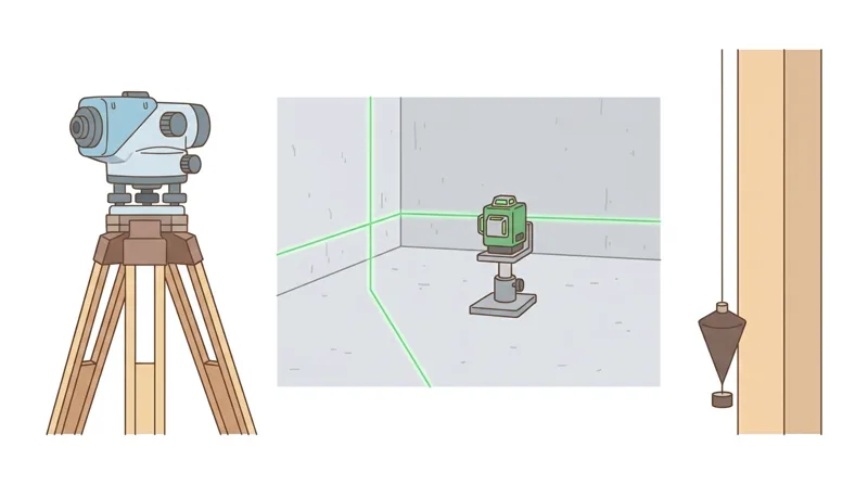
高低差を測る水準測量には「レベル(オートレベル)」、距離と角度を同時に測るには「トータルステーション」、水平線(ろく)と垂直線(たち)を同時照射するには「レーザー墨出し器」を使います。
An 'auto-level' is used for leveling surveys to measure height differences, a 'total station' measures both distance and angles simultaneously, and a 'laser line level' projects horizontal and vertical lines at once.
気泡管で水平を調べる「水平器」、円錐状のおもりで垂直を確かめる「下げ振り」、辺の比「3:4:5(サシゴ)」で直角を出す「おおがね」も現場で重要な道具です。
A 'spirit level (Suiheiki)' checks horizontal level with a bubble vial, a conical 'plumb bob (Sagefuri)' checks verticality of columns/formwork, and a large carpenter's triangle 'Oogane' uses the Pythagorean side ratio '3 : 4 : 5 (Sashigo)' to lay out right angles.
Key points
- 高さの基準点はベンチマーク(BM)、水平の基準墨は陸墨(水墨)、基準線から離して引く墨は逃げ墨(返り墨)という。
The elevation reference point is a Benchmark (BM), the horizontal reference mark is Rokuzumi, and a parallel offset line is Nigezumi. - 高低差測定にはオートレベル、距離と角度の同時測定にはトータルステーション、垂直確認には下げ振りを使う。
Use an auto-level for height differences, a total station for simultaneous distance/angle measurement, and a plumb bob (Sagefuri) for verticality. - 直角を出す「おおがね」の辺の比は3:4:5(サシゴ)であり、レベル測量でBMの後視1,500mm・前視1,800mmなら測定点はBMより300mm低い(-300mm)。
An Oogane triangle uses the 3:4:5 ratio; in leveling, if the backsight on BM is 1,500 mm and foresight at point A is 1,800 mm, point A is 300 mm lower than BM (-300 mm).
| Word | Meaning |
|---|---|
| 陸墨(水墨) | Horizontal reference mark (Rokuzumi / Mizuzumi) |
| 逃げ墨(返り墨) | Offset reference mark (Nigezumi / Kaerizumi) |
| 遣り方(丁張り) | Batter boards (Yarikata / Chouhari) |
| トータルステーション | Total station (electro-optical distance & angle meter) |
建築単位・部位と寸法の用語
Traditional Units, Building Parts, and Dimension Terminology
日本の建築単位では「一尺(約303mm)」の6倍である「一間」は約1,818mm、「1坪(畳2枚分)」は約3.3平方メートル(㎡)です。屋根の「4寸勾配」は水平10寸に対して垂直に4寸上がる傾きを指します。
In traditional Japanese building units, '1 ken' (6 times 1 shaku ≈ 303 mm) is about 1,818 mm, and '1 tsubo' (the area of 2 tatami mats) is about 3.3 m². A '4-sun roof pitch' rises 4 sun vertically for every 10 sun (1 shaku) horizontally (4/10 slope).
鉄骨の周りに鉄筋を組んでコンクリートを打つ構造を「SRC造(鉄骨鉄筋コンクリート造)」といい、木造や鉄骨造で屋根の一番高い棟木の取付けが完了することを「上棟(棟上げ)」といいます。
A structure combining a steel frame encased in rebar and concrete is an 'SRC structure (steel reinforced concrete)', and completing the installation of the highest roof ridge beam (Munagi) in timber or steel framing is called 'topping out (Joutou / Muneage)'.
部材の上面を「上端(天端)」、下面を「下端」、2つの部材表面に段差がなく平らに揃った状態を「面一」、異なる部材が出会う接合箇所を「取合い」といいます。
The top surface of a member is 'Uwaba (Tenba)', the bottom surface is 'Shitaba', two surfaces joined completely flush without steps are 'Tsura-ichi', and the junction where two different materials or trades meet is 'Toriai'.
向かい合う壁や柱の内側どうしの距離を「内法」といい、隣り合う鉄筋の表面間距離を「あき」、鉄筋の中心間距離を「間隔(ピッチ)」といいます。
The clear inside distance between facing walls or columns is 'inside dimension (Uchinori)'; the clear surface-to-surface distance between adjacent rebars is 'clear spacing (Aki)', while the center-to-center distance is 'spacing (Pitch / Kankaku)'.
Key points
- 一間(六尺)は約1,818mm、1坪は約3.3㎡、4寸勾配は水平10寸に垂直4寸上がる傾きである。
1 ken is approx. 1,818 mm, 1 tsubo is approx. 3.3 m², and a 4-sun pitch rises 4 sun vertically per 10 sun horizontally. - 部材の底面は「下端」、段差なく平らな状態は「面一」、異種部材の接合部は「取合い」という。
The bottom surface is 'Shitaba', a flush joint is 'Tsura-ichi', and the interface between different parts is 'Toriai'. - 壁の内側間の寸法は「内法」、鉄筋の表面間は「あき」、鉄筋の中心間は「間隔(ピッチ)」という。
Clear interior width is 'Uchinori', surface-to-surface rebar gap is 'Aki', and center-to-center rebar distance is 'Kankaku (Pitch)'.
| Word | Meaning |
|---|---|
| 面一 | Flush surface alignment (Tsura-ichi) |
| 取合い | Interface / Junction between parts (Toriai) |
| 内法 | Clear inside dimension (Uchinori) |
| 間隔(ピッチ) | Center-to-center spacing / Pitch (Kankaku) |
建築図面の種類と図面記号
Types of Architectural Drawings and Drawing Symbols
敷地と道路・建物位置を示す「配置図」、建物を水平に切って真上から見た「平面図」、外観を東西南北から見た「立面図」、垂直に切って高さ関係を示す「断面図」が基本図面です。
Basic drawings include the 'site plan (Haichizu)' showing lot boundaries, roads, and building placement; 'floor plan (Heimenzu)' cut horizontally and viewed from above; 'elevation (Ritsumenzu)' viewing exterior walls from four directions; and 'section (Danmenzu)' cut vertically to show floor heights.
さらに基礎から軒先までの垂直断面詳細を示す「矩計図」、室内4面の壁を並べた「展開図」、天井の照明や割付を示す「天井伏図」、基礎や杭の配置を示す「基礎伏図」があります。
Detailed drawings include the 'wall section detail (Kanabakarizu)' cut vertically from foundation to eaves, 'interior elevation (Tenkaizu)' showing all four interior walls of a room, 'reflected ceiling plan (Tenjou-fusezu)', and 'foundation plan (Kiso-fusezu)'.
建築図面で単位を省略した数字は原則「ミリメートル(mm)」を表し、一点鎖線は「中心線(通り芯)」、破線は「見えない部分の形」を表します。
Numbers without unit symbols on Japanese architectural drawings are in 'millimeters (mm)' in principle; a chain line (dash-dot line) indicates a 'centerline (grid line)', and a dashed line indicates 'hidden outlines'.
記号では「FL」が床仕上がり面高さ、「FIX」が開閉できないはめ殺し窓、構造部材では「C=柱、G=大梁、B=小梁、S=床版(スラブ)」を表します。
Among symbols, 'FL' denotes finished floor level, 'FIX' denotes a fixed non-opening window, and structural member symbols are 'C = Column, G = Girder (main beam), B = Beam (secondary beam), S = Slab'.
Key points
- 平面図は水平断面、立面図は外観、矩計図は基礎から軒先までの垂直断面詳細図、展開図は室内壁面図である。
Heimenzu is a floor plan, Ritsumenzu is an exterior elevation, Kanabakarizu is a vertical wall section from foundation to eaves, and Tenkaizu shows interior room walls. - 図面の寸法単位は原則mm、一点鎖線は中心線(通り芯)、破線は見えない部分を表す。
Default drawing units are mm; chain lines represent centerlines/grid lines, and dashed lines represent hidden edges. - FLは床仕上がり面、FIXは固定窓(はめ殺し窓)、Cは柱・Gは大梁・Bは小梁・Sはスラブを表す。
FL means finished floor level, FIX means fixed window, and C = Column, G = Girder, B = Beam, S = Slab.
| Word | Meaning |
|---|---|
| 矩計図 | Detailed vertical wall section (Kanabakarizu) |
| 展開図 | Interior room elevation drawing (Tenkaizu) |
| 天井伏図 | Ceiling plan (Tenjou-fusezu) |
| FL(床面) | Finished Floor Level (FL) |
材料の拾い出しと現場の実務計算
Material Quantity Takeoff and Practical Site Calculations
図面や仕様書から工事に必要な材料の種類や数量を算出することを「拾い出し」といいます。縮尺1/50の図面で80mm(8cm)の壁の実寸は80×50=4,000mm(4.0m)です。
Calculating required material types, quantities, and labor from drawings and specifications is called 'quantity takeoff (Hiroidashi)'. A wall measuring 80 mm (8 cm) on a 1/50 scale plan has an actual length of 80 × 50 = 4,000 mm (4.0 m).
水平4mに1/100の水勾配なら高低差は40mm、階高2,800mmで14段の階段蹴上げは200mmです。6,000mmに支柱5本(4間隔)のピッチは1,500mm、幅2,000mmに200mm間隔の鉄筋は11本です。
Slope & spacing calculations: a 1/100 drainage slope over 4 m gives a 40 mm height drop; a 2,800 mm story height divided into 14 steps gives a 200 mm riser height; 5 posts spaced equally along 6,000 mm (4 intervals) have a 1,500 mm pitch; rebars at 200 mm pitch across 2,000 mm (including both ends) require (2,000 ÷ 200) + 1 = 11 bars.
3×6mの壁から2×1.5mの戸を引く塗装は15㎡(100㎡×0.25kg×2回=50kg)、周長21m-開口1mの幅木は20m、3,640mm幅に910mm幅ボードは4枚、4.0×1.2m塀のブロック(0.4×0.2m)は60個です。
Area & panel calculations: a 3 m × 6 m wall minus a 2 m × 1.5 m door leaves 15.0 m² of painting area (100 m² × 0.25 kg/m² × 2 coats = 50 kg paint); a 6 m × 4.5 m room (21 m perimeter) minus a 1 m doorway needs 20.0 m of baseboard; a 3,640 × 1,820 mm wall takes 4 gypsum boards of 910 × 1,820 mm; a 4,000 × 1,200 mm wall takes 60 concrete blocks of 400 × 200 mm.
縦5m×横4m×厚さ0.15mの土間コン体積は3.0㎥、残土12.0㎥は3.0㎥積みダンプ4台分、1:3モルタルでセメント50Lなら砂は150L、1.5kg/mで4mの鉄筋20本の質量は120kgです。
Volume & weight calculations: a 5 m × 4 m × 0.15 m concrete slab is 3.0 m³; hauling 12.0 m³ of excavated soil in a 3.0 m³ dump truck takes 4 loads; 1:3 mortar using 50 L of cement requires 150 L of sand; twenty 4 m rebars weighing 1.5 kg/m weigh 120 kg in total.
Key points
- 幅2,000mmに200mm間隔で鉄筋を並べる本数は「間隔数10+両端の1=11本」、5本の支柱を6,000mmに等間隔で立てるピッチは「6,000÷4間隔=1,500mm」である。
Rebars at 200 mm pitch over 2,000 mm require (2,000÷200)+1 = 11 bars; 5 posts spaced equally over 6,000 mm have a pitch of 6,000÷4 = 1,500 mm. - 塗装面積や幅木の長さは開口部(ドア等)の面積・幅を差し引いて算出する。
Subtract door/window opening areas or widths when calculating paint area or baseboard length. - 土間コン体積は「縦×横×厚さ(m換算)」で求め、1:3モルタルでセメント50Lに対する砂は150Lである。
Concrete volume = Length × Width × Thickness (in meters); 1:3 mortar with 50 L of cement requires 150 L of sand.
| Word | Meaning |
|---|---|
| 拾い出し | Material quantity takeoff (Hiroidashi) |
| 水勾配 | Drainage slope (Mizukoubai) |
| 蹴上げ | Stair riser height (Keage) |
Layout Marking, Surveying, Dimensions, and Terms
Practice this chapter in the appOfficial references
- 建設分野特定技能1号評価試験(一般社団法人建設技能人材機構 JAC) — https://jac-skill.or.jp/exam.html
- 建設分野特定技能評価試験 試験実施要領(国土交通省) — https://www.mlit.go.jp/tochi_fudousan_kensetsugyo/content/001519991.pdf