
Electrical Machines, Switching/Control Devices, and Measuring Instruments (Rotating Machines, Transformers, Circuit Breakers, Relays, Meters)
電気機器・開閉制御器具・電気計測器(回転機・変圧器・遮断器・継電器・計器)
Electrical Equipment Assembly – Control Panels 電気機器組立て (Grade 2 theory) · 技能検定「電気機器組立て」2級 学科(配電盤・制御盤組立て) · Written by Tokutei Pass based on the official study texts; not copied verbatim.
三相誘導電動機の原理・同期速度・すべり・回転方向の切換え
Principles, Synchronous Speed, Slip, and Reversing Rotation of Three-Phase Induction Motors
工場の動力源として最も広く使われる「三相誘導電動機(かご形・巻線形)」は、固定子巻線に三相交流を流して作られる「回転磁界」によって回転子に誘導電流を流し、電磁力で回転する機器です。
The "three-phase induction motor (squirrel-cage and wound-rotor types)", most widely used as a power source in factories, passes three-phase AC through the stator windings to create a "rotating magnetic field", inducing current in the rotor and rotating it by electromagnetic force.
回転磁界の回転速度である「同期速度 Ns(単位:min⁻¹)」は、電源周波数 f(Hz)に比例し、磁極数 p に反比例するため「Ns = 120 × f ÷ p」の公式で求められます。
The rotational speed of the rotating magnetic field, called "synchronous speed Ns (unit: min⁻¹)", is proportional to the power supply frequency f (Hz) and inversely proportional to the number of magnetic poles p, calculated by the formula "Ns = 120 × f ÷ p".
例えば4極(p=4)の誘導電動機では、50Hz地域での同期速度は「120 × 50 ÷ 4 = 1500 min⁻¹」、60Hz地域では「120 × 60 ÷ 4 = 1800 min⁻¹」となります。したがつて60Hz用電動機を50Hz電源で運転すると、回転速度は約17%遅くなります(速くなるというのは誤りです)。
For example, in a 4-pole (p = 4) induction motor, the synchronous speed in a 50Hz region is "120 × 50 ÷ 4 = 1500 min⁻¹", and in a 60Hz region is "120 × 60 ÷ 4 = 1800 min⁻¹". Therefore, operating a 60Hz motor on a 50Hz power supply slows the rotational speed by about 17% (stating that it runs faster is incorrect).
誘導電動機の実際の回転速度 N は同期速度 Ns より少し遅くなり、その割合を「すべり s =(Ns − N)÷ Ns」といいます。また回転子に流れる二次電流の周波数は「f2 = s × f」で表されます。
The actual rotational speed N of an induction motor is slightly slower than the synchronous speed Ns, and this ratio is called "slip s = (Ns − N) ÷ Ns". In addition, the frequency of the secondary current flowing in the rotor is expressed as "f2 = s × f".
三相誘導電動機の回転方向を逆転させるには、主回路の3本の電源線(R・S・T)のうち「いずれか2本の接続を入れ替える」ことで回転磁界の向きを反転させます。なお単相誘導電動機は電源2線を差し替えても逆転せず、始動巻線と主巻線の一方の接続を切換えます。
To reverse the rotational direction of a three-phase induction motor, "swap the connections of any two of the three power supply wires (R, S, T)" in the main circuit to reverse the direction of the rotating magnetic field. Note that a single-phase induction motor will not reverse by swapping the two power wires; instead, the connection of either the starting winding or main winding must be switched.
Key points
- 同期速度は「Ns = 120 × f ÷ p」で求まり、4極機は50Hzで1500 min⁻¹、60Hzで1800 min⁻¹となる
Synchronous speed is found by "Ns = 120 × f ÷ p"; a 4-pole machine runs at 1500 min⁻¹ at 50Hz and 1800 min⁻¹ at 60Hz - すべりは「s =(Ns − N)÷ Ns」であり、60Hz用誘導電動機を50Hzで運転すると回転速度は低下する
Slip is "s = (Ns − N) ÷ Ns", and operating a 60Hz induction motor at 50Hz reduces its rotational speed - 三相誘導電動機の逆転は「三相電源線3本のうち2本を入れ替える」ことで行う(単相電動機は電源線入替えでは逆転しない)
Reversing a three-phase induction motor is done by "swapping two of the three power supply wires" (a single-phase motor does not reverse by swapping power supply wires)
| Word | Meaning |
|---|---|
| 三相誘導電動機と回転磁界 | Three-phase induction motor and rotating magnetic field |
| 同期速度(Ns = 120 × f ÷ p) | Synchronous speed (Ns = 120 × f ÷ p) |
| すべり(s)と二次周波数 | Slip (s) and secondary frequency |
| 正転・逆転(三相のうち2本の入替え) | Forward and reverse rotation (swapping 2 of 3 phases) |
かご形誘導電動機の始動法(Y-△始動)・速度制御・制動法
Starting Methods (Star-Delta Starting), Speed Control, and Braking of Squirrel-Cage Induction Motors
三相かご形誘導電動機を定格電圧のまま直接始動する「じか入れ始動法(全電圧始動)」は、小容量機で広く使われますが、定格電流の5〜7倍の大きな始動電流が流れて電源電圧降下を招きます。
"Direct-on-line starting (full-voltage starting)", which starts a three-phase squirrel-cage induction motor directly at rated voltage, is widely used for small-capacity motors, but draws a large starting current of 5 to 7 times the rated current, causing supply voltage drops.
中容量以上のかご形誘導電動機で始動電流を抑える方法が「スター・デルタ(Y-△)始動法」です。始動時に巻線をY結線にすると相電圧が1÷1.73倍になり、始動電流と始動トルクは直入れ(△結線)の「1/3(3分の1)」に減少し、加速後に△結線へ切換えます。
A representative method to suppress starting current in medium- or larger-capacity squirrel-cage induction motors is "star-delta (Y-△) starting". Connecting the windings in star (Y) at startup reduces phase voltage to 1÷1.73 times, reducing both starting current and starting torque to "1/3 (one-third)" of direct-on-line (△ connection), before switching to △ connection after acceleration.
その他、かご形誘導電動機の減電圧始動法には、主回路に直列にリアクトルを入れる「リアクトル始動法」や、単巻変圧器を用いる「補償器始動法(コンドルファ始動法)」があります。なお「二次抵抗始動法」は巻線形誘導電動機の始動法であり、かご形には使えません。
Other reduced-voltage starting methods for squirrel-cage induction motors include "reactor starting" (inserting a reactor in series with the main circuit) and "autotransformer starting (Korndorfer starting)". Note that "secondary resistance starting" is for wound-rotor induction motors and cannot be used for squirrel-cage motors.
誘導電動機の速度制御には、直流を任意の周波数・電圧の交流に変換する「インバータ(VVVF制御)」や極数変換法が用いられます。電動機の発生トルクは印加電圧の2乗に比例するため、インバータでは電圧Vと周波数fの比(V/f)を一定に保って制御します。
For speed control of induction motors, an "inverter (VVVF control)" that converts DC into AC of arbitrary frequency and voltage, or pole-changing methods, are used. Because motor torque is proportional to the square of applied voltage, an inverter controls the motor while keeping the ratio of voltage V to frequency f (V/f) constant.
電動機を素早く停止させる電気的制動法には、発電機として電力を電源へ返す「回生制動」、固定子巻線に直流を流して運動エネルギーを熱に変える「発電制動(ダイナミックブレーキ)」、回転中に逆転方向の磁界をかける「逆相制動(プラッギング)」があります。
Electrical braking methods to stop a motor quickly include "regenerative braking" (returning power to the supply as a generator), "dynamic braking" (passing DC through stator windings to convert kinetic energy into heat), and "plugging (reverse-phase braking)" (applying a reverse magnetic field while rotating).
Key points
- かご形誘導電動機の始動法には「じか入れ始動・Y-△始動・リアクトル始動・補償器始動」があり、二次抵抗始動は巻線形用である
Starting methods for squirrel-cage induction motors include "direct-on-line, Y-△, reactor, and autotransformer starting", whereas secondary resistance starting is for wound-rotor motors - Y-△(スター・デルタ)始動法では、始動電流と始動トルクがともに直入れ始動時の「1/3」になる
In Y-△ (star-delta) starting, both starting current and starting torque become "1/3" of those in direct-on-line starting - 直流を可変周波数・可変電圧の交流に変換する装置を「インバータ」といい、誘導電動機の円滑な速度制御に使われる
A device that converts DC into AC of variable frequency and variable voltage is called an "inverter", used for smooth speed control of induction motors
| Word | Meaning |
|---|---|
| じか入れ始動法とスター・デルタ(Y-△)始動法 | Direct-on-line starting and star-delta (Y-△) starting |
| リアクトル始動法と補償器始動法 | Reactor starting and autotransformer (compensator) starting |
| インバータ(直流から交流への変換・VVVF) | Inverter (DC-to-AC conversion, VVVF) |
| 回生制動・発電制動・逆相制動 | Regenerative braking, dynamic braking, and plugging |
変圧器(巻線比・鉄損と銅損・並行運転条件)と直流機・サーボモータ
Transformers (Turns Ratio, Iron and Copper Losses, Parallel Operation), DC Machines, and Servo Motors
変圧器(トランス)は電磁誘導作用により交流電圧を変成する静止機器です。一次巻数 N1 と二次巻数 N2 の比「a = N1 ÷ N2」を巻数比といい、電圧比は「V1 ÷ V2 = a」、電流比は逆比の「I2 ÷ I1 = a」、二次インピーダンス Z2 の一次換算値は「Z1 = a² × Z2」となります。
A transformer is a static machine that transforms AC voltage by electromagnetic induction. The ratio of primary turns N1 to secondary turns N2, "a = N1 ÷ N2", is the turns ratio; the voltage ratio is "V1 ÷ V2 = a", the current ratio is the inverse "I2 ÷ I1 = a", and the secondary impedance Z2 referred to the primary side is "Z1 = a² × Z2".
変圧器の損失は、電圧をかけておくだけで鉄心に常時発生する「無負荷損(=鉄損:ヒステリシス損とうず電流損の和)」と、負荷電流の2乗に比例して巻線抵抗で発生する「負荷損(=銅損)」に分かれます。変圧器の効率は「鉄損と銅損が等しくなるとき」に最大になります。
Transformer losses are divided into "no-load loss (= iron loss: sum of hysteresis loss and eddy current loss)", which occurs constantly in the iron core whenever voltage is applied, and "load loss (= copper loss)", which occurs in the winding resistance proportional to the square of load current. Transformer efficiency is maximum when "iron loss equals copper loss".
変圧器の冷却方式には油入自冷式(ONAN)や乾式自冷式(AN)などがあります。また2台の変圧器を「並行運転」するための条件は、①極性が一致すること、②一次・二次定格電圧(巻数比)が等しいこと、③百分率インピーダンス降下が等しいこと、④三相変圧器では角変位(結線方式による位相変位)が一致することです。
Transformer cooling methods include oil-immersed natural cooling (ONAN) and dry-type natural cooling (AN). The conditions for "parallel operation" of two transformers are: ① Identical polarity, ② Equal primary and secondary rated voltages (turns ratio), ③ Equal percentage impedance drop, and ④ For three-phase transformers, identical angular displacement (phase shift due to winding connection).
直流電動機・直流発電機の電機子巻線には、並列回路数が磁極数と同じになる「重ね巻き(低電圧・大電流機向き)」と、磁極数に関係なく並列回路数が常に2となる「波巻き(高電圧・小電流機向き)」の2種類があります(試験では重ね巻きと波巻きの用途を入れ替えたひっかけが頻出します)。
Armature windings of DC motors and generators are of two types: "lap winding (suited for low-voltage, high-current machines)", where the number of parallel paths equals the number of poles, and "wave winding (suited for high-voltage, low-current machines)", where the number of parallel paths is always 2 regardless of pole count (exam questions frequently swap lap and wave winding applications as a trap).
また自動機械の位置決め制御には、入力パルス数に比例した角度だけ正確に回転する「ステッピングモータ(パルスモータ)」や、エンコーダ(回転検出器)で位置や速度を常時フィードバック制御する「サーボモータ」が用いられます。
Furthermore, for positioning control in automated machinery, "stepping motors (pulse motors)" that rotate by an exact angle proportional to the number of input pulses, and "servo motors" that continuously apply feedback control of position and speed using an encoder (rotation detector), are used.
Key points
- 変圧器の無負荷損は「鉄損(ヒステリシス損+うず電流損)」、負荷損は「銅損」であり、鉄損=銅損のとき効率が最大となる
Transformer no-load loss is "iron loss (hysteresis loss + eddy current loss)", load loss is "copper loss", and efficiency is maximum when iron loss = copper loss - 変圧器の並行運転では「極性・巻数比(定格電圧)・百分率インピーダンス・三相角変位」を一致させる
In parallel operation of transformers, "polarity, turns ratio (rated voltage), percentage impedance, and three-phase angular displacement" must match - 直流機の電機子巻線は、「重ね巻き=低電圧・大電流用」、「波巻き=高電圧・小電流用」である
For DC machine armature windings, "lap winding = low voltage, high current" and "wave winding = high voltage, low current"
| Word | Meaning |
|---|---|
| 変圧器の巻数比と鉄損・銅損 | Transformer turns ratio, iron loss, and copper loss |
| 変圧器の並行運転条件 | Conditions for parallel operation of transformers |
| 重ね巻き(低圧大電流)と波巻き(高圧小電流) | Lap winding (low voltage, high current) and wave winding (high voltage, low current) |
| ステッピングモータとサーボモータ | Stepping motor and servo motor |
遮断器(CB)と断路器(DS)の機能・種類・文字記号と漏電遮断器
Functions, Types, and Letter Symbols of Circuit Breakers (CB), Disconnectors (DS), and Earth Leakage Breakers
「遮断器(CB)」は消弧装置を備え、平常時の負荷電流の開閉だけでなく、短絡や地絡事故時の大電流を安全に遮断できる機器です。これに対し「断路器(DS:ディスコン)」は消弧能力を持たないため、「負荷電流が流れていない無負荷状態」で回路を切り離すためにのみ用いられます。
A "circuit breaker (CB)" is equipped with an arc-extinguishing device and can safely interrupt not only normal load currents but also large currents during short-circuit or ground-fault accidents. In contrast, a "disconnecting switch (DS: disconnector)" has no arc-extinguishing capability and is used only to isolate circuits under "no-load conditions when no load current is flowing".
交流電流は1サイクルごとに2回「電流ゼロ点(電流値が0になる瞬間)」を通過するためアークが消えやすく、電流ゼロ点がない直流電流に比べて「交流の方が直流よりも電流を遮断しやすい」という重要な性質があります。
Because alternating current passes through a "current zero point (the instant when current value becomes 0)" twice every cycle, arcs extinguish easily; thus, AC has the important property that "alternating current is easier to interrupt than direct current", which has no current zero point.
遮断器の種類とJEM文字記号は、消弧媒体により「油遮断器=OCB」「真空遮断器=VCB」「ガス遮断器(SF6ガス)=GCB」「磁気遮断器=MBB」「気中遮断器=ACB」「配線用遮断器=MCCB」「漏電遮断器=ELCB(またはELB)」と定められています。
Circuit breaker types and JEM letter symbols according to arc-extinguishing medium are defined as: "Oil circuit breaker = OCB", "Vacuum circuit breaker = VCB", "Gas circuit breaker (SF6 gas) = GCB", "Magnetic blow-out circuit breaker = MBB", "Air circuit breaker = ACB", "Molded case circuit breaker = MCCB", and "Earth leakage circuit breaker = ELCB (or ELB)".
学科試験では、「磁気遮断器の記号をMCBやACBとする」あるいは「ACBを界磁遮断器とする」といった誤りの選択肢が毎年のように出題されるため、「磁気遮断器=MBB、気中遮断器=ACB」を正確に区別します。
In written exams, incorrect options such as "giving MCB or ACB as the symbol for a magnetic circuit breaker" or "defining ACB as a field circuit breaker" appear almost every year, so accurately distinguish "Magnetic circuit breaker = MBB, Air circuit breaker = ACB".
「漏電遮断器(ELCB)」は、主回路の3本(または2本)の電線を一括して貫通させた「ゼロ相変流器(ZCT)」によって地絡電流(漏電電流)を検出し、回路を遮断して感電や火災を防ぎます(「変圧器によって地絡電流を検出する」という記述は誤りです)。
An "earth leakage circuit breaker (ELCB)" detects ground-fault current (leakage current) by a "zero-phase current transformer (ZCT)" through which all 3 (or 2) main circuit wires pass together, tripping the circuit to prevent electric shock and fire (statements that it "detects ground-fault current by a voltage transformer" are incorrect).

Key points
- 断路器(DS)は負荷電流を遮断できず無負荷時にのみ開閉し、交流は電流ゼロ点があるため直流より遮断しやすい
A disconnecting switch (DS) cannot interrupt load current and operates only at no load; AC is easier to interrupt than DC because it has current zero points - 遮断器の文字記号は「真空=VCB、ガス=GCB、磁気=MBB、気中=ACB、配線用=MCCB、油=OCB」である
Circuit breaker letter symbols are "Vacuum = VCB, Gas = GCB, Magnetic = MBB, Air = ACB, Molded case = MCCB, Oil = OCB" - 漏電遮断器(ELCB)は、変圧器ではなく「ゼロ相変流器(ZCT)」によって地絡電流を検出する
An earth leakage circuit breaker (ELCB) detects ground-fault current using a "zero-phase current transformer (ZCT)", not a voltage transformer
| Word | Meaning |
|---|---|
| 遮断器(CB)と断路器(DS:無負荷開閉) | Circuit breaker (CB) and disconnecting switch (DS: no-load switching) |
| VCB(真空)・GCB(ガス)・MBB(磁気)・ACB(気中) | VCB (vacuum), GCB (gas), MBB (magnetic), ACB (air) |
| 配線用遮断器(MCCB)と漏電遮断器(ELCB) | Molded case circuit breaker (MCCB) and earth leakage circuit breaker (ELCB) |
| ゼロ相変流器(ZCT)と支持がいし | Zero-phase current transformer (ZCT) and support insulator |
電磁接触器(MC)・電磁開閉器(MS)・半導体接触器(SSR)とヒューズ
Magnetic Contactors (MC), Magnetic Switches (MS), Semiconductor Contactors (SSR), and Fuses
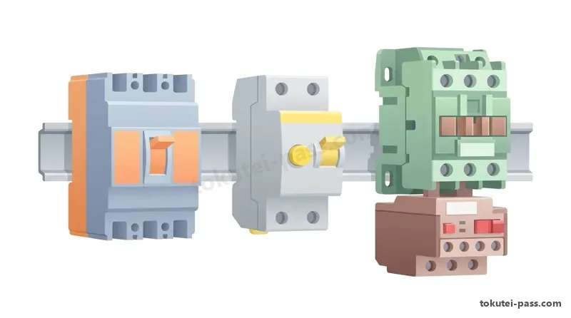
「電磁接触器(MC)」は、操作コイルに電流を流して電磁石で主接点および補助接点(a接点・b接点)を開閉し、電動機等の負荷電流を頻繁にON/OFFできる器具です。交流電磁石の鉄心には、うなり音や振動を防ぐ「くま取りコイル」が設けられています。
A "magnetic contactor (MC)" passes current through an operating coil so an electromagnet opens and closes main contacts and auxiliary contacts (a-contacts and b-contacts), frequently switching load currents of motors, etc. The iron core of an AC electromagnet is provided with a "shading coil" to prevent humming noise and vibration.
「電磁開閉器(MS:マグネットスイッチ)」は、負荷を開閉する「電磁接触器(MC)」と、熱膨張率の異なる2枚の金属を貼り合わせたバイメタルで過負荷電流を検出する「サーマルリレー(熱動継電器 THR)」を一組に組み合わせたものです。
A "magnetic switch (MS)" combines into a single unit a "magnetic contactor (MC)" that switches the load and a "thermal relay (THR)" that detects overload current using a bimetal strip made by bonding two metals with different thermal expansion coefficients.
電磁接触器やサーマルリレーには短絡大電流を遮断する能力がないため、その電源側には短絡保護用として必ず「配線用遮断器(MCCB)」または「ヒューズ」を設けます。なおJEMでは直流操作の電磁接触器が定格制御電源電圧の85%〜110%で確実に動作することなどを定めています。
Because magnetic contactors and thermal relays cannot interrupt large short-circuit currents, a "molded case circuit breaker (MCCB)" or "fuse" must always be installed on their power supply side for short-circuit protection. Furthermore, JEM specifies that DC-operated magnetic contactors must operate reliably at 85% to 110% of rated control supply voltage.
サイリスタやトライアックなどの半導体素子を用いた無接点式の「半導体接触器(SSR:ソリッドステートリレー)」は、可動部がないため長寿命でアークや開閉騒音が出ず、電気炉のヒータ温度制御のような「高頻度開閉」に極めて適しています。
A contactless "semiconductor contactor (SSR: solid state relay)" using semiconductor devices such as thyristors or triacs has no moving parts, offering long life without arcs or switching noise, making it extremely well suited for "high-frequency switching" such as electric furnace heater temperature control.
また「ヒューズ(配線用ヒューズ・高圧限流ヒューズPF)」は、過大な短絡電流が流れたときに内部の可溶体(エレメント)が瞬時に溶断し、電流の波高値が最大に達する前に抑え込んで遮断する優れた「限流作用」を持っています。
In addition, "fuses (low-voltage fuses and high-voltage current-limiting fuses PF)" have an excellent "current-limiting action" in which the internal fusible element melts instantaneously when excessive short-circuit current flows, suppressing and interrupting the current before its peak value reaches maximum.

Key points
- 「電磁接触器(MC)」と過負荷保護用の「サーマルリレー(熱動継電器 THR)」を組み合わせたものを「電磁開閉器(MS)」という
The combination of a "magnetic contactor (MC)" and an overload-protecting "thermal relay (THR)" is called a "magnetic switch (MS)" - 半導体接触器(SSR)は無接点で摩耗や騒音がなく、ヒータ回路等の「高頻度開閉」に適している
A semiconductor contactor (SSR) is contactless, free of wear and noise, and suited for "high-frequency switching" in heater circuits, etc. - 高圧限流ヒューズや配線用ヒューズは、短絡電流を急速に溶断して抑制する「限流作用」を持ち、短絡保護に用いられる
High-voltage current-limiting fuses and low-voltage fuses have a "current-limiting action" that rapidly melts to suppress short-circuit current, used for short-circuit protection
| Word | Meaning |
|---|---|
| 電磁接触器(MC)とくま取りコイル | Magnetic contactor (MC) and shading coil |
| 電磁開閉器(MC+サーマルリレーTHR) | Magnetic switch (MC + thermal relay THR) |
| 半導体接触器(SSR:無接点・高頻度開閉) | Semiconductor contactor (SSR: contactless, high-frequency switching) |
| 配線用ヒューズと限流作用 | Power fuse and current-limiting action |
制御用・保護継電器と操作用スイッチ類(回転形スイッチのハンドル形状)
Control/Protective Relays and Operating Switches (Rotary Switch Handle Shapes)
制御回路で信号の中継や増幅・接点増設を行う「補助継電器(制御リレー)」のうち、不活性ガスと磁性金属片(リード)をガラス管内に封入し、外部コイルの磁界で開閉する「リードリレー」は、小形で接触信頼性が高く高速動作できる特徴があります。
Among "auxiliary relays (control relays)" that relay or amplify signals and expand contacts in control circuits, a "reed relay"—which seals inert gas and magnetic metal strips (reeds) inside a glass tube and switches via an external coil's magnetic field—features compact size, high contact reliability, and high-speed operation.
なお、絶縁物の表面に接する銀電極間に直流電圧が長時間かかり湿気が加わると、銀イオンが陰極側へ樹枝状に移動して絶縁劣化や短絡を起こす「銀移行現象(シルバーマイグレーション)」が生じることがあります。
Note that when DC voltage is applied for a long time between silver electrodes touching an insulating surface in the presence of moisture, silver ions migrate in a dendritic (tree-like) pattern toward the cathode, causing insulation degradation or short circuits known as "silver migration".
電力回路の異常を検出して遮断器に引外し指令を出す「保護継電器」には、過電流継電器(OCR:器具番号51)、不足電圧継電器(UVR:27)、過電圧継電器(OVR:59)、地絡方向継電器(DGR:67)、地絡過電圧継電器(OVGR:64)などがあります。
"Protective relays" that detect abnormalities in power circuits and issue trip commands to circuit breakers include overcurrent relays (OCR: device number 51), undervoltage relays (UVR: 27), overvoltage relays (OVR: 59), directional ground relays (DGR: 67), and ground overvoltage relays (OVGR: 64).
盤面で作業者が操作する器具には、指で押している間だけ動作する「押しボタンスイッチ」や、つまみを回して切換える「回転形制御スイッチ(コントロールスイッチ・カムスイッチ)」があります。回転形制御スイッチには、手を離すと元の位置に戻る「自動復帰形」と、回した位置を保つ「ノッチ形(手動復帰形)」があります。
Devices operated by workers on the panel front include "pushbutton switches" that actuate only while pressed by a finger, and "rotary control switches (control switches / cam switches)" switched by turning a knob. Rotary control switches include "spring-return (automatic return) types" that return to the original position when released, and "notch (manual return) types" that hold the turned position.
回転形制御スイッチの操作ハンドル(とって)の形状には、用途別の誤操作防止のため「ピストル形(遮断器操作用等)」「オーバル形(卵形・計器切替用等)」「丸形(ロゼット形)」などが用いられます(「ステッキ形」というハンドル形状は用いられません)。
For the operating handle shapes of rotary control switches, "pistol type (for circuit breaker operation, etc.)", "oval type (egg-shaped, for meter selector switching, etc.)", and "round type (rosette type)" are used to prevent misoperation by application (a "stick type" handle shape is not used).
Key points
- ガラス管内に磁性接点片を封入した「リードリレー」は高速・高信頼性であり、銀電極では湿気と直流電圧による「銀移行現象」に注意する
A "reed relay" with magnetic contact strips sealed in a glass tube offers high speed and reliability; with silver electrodes, beware of "silver migration" caused by moisture and DC voltage - 回転形制御スイッチには、手を離すと中立位置に戻る「自動復帰形」と位置を保持する「手動復帰形(ノッチ形)」がある
Rotary control switches include "automatic-return types" that return to neutral when released and "manual-return (notch) types" that hold their position - 制御スイッチのとって(ハンドル)形状には「ピストル形・オーバル形・丸形(ロゼット形)」などがあり、「ステッキ形」は用いられない
Control switch handle shapes include "pistol, oval, and round (rosette) types", whereas "stick type" is not used
| Word | Meaning |
|---|---|
| リードリレーと銀移行現象(マイグレーション) | Reed relay and silver migration |
| 保護継電器(OCR・UVR・OVR・DGR) | Protective relays (OCR, UVR, OVR, DGR) |
| 回転形制御スイッチ(自動復帰形・手動復帰形) | Rotary control switch (automatic return / manual return) |
| ハンドル形状(ピストル形・オーバル形・丸形) | Handle shapes (pistol type, oval type, round type) |
計器用変成器(CT・VT・PD)の変成比計算とクランプメータの測定法
Ratio Calculations of Instrument Transformers (CT, VT, PD) and Clamp Meter Measurement
大電流回路の電流測定に用いる「変流器(CT)」には、一次導体(母線や電線)を鉄心中央の窓穴に通す「貫通形CT」や、一次巻線を持つ巻線形CTがあります。CTの二次定格電流は標準で「5A(または1A)」です。
"Current transformers (CT)" used to measure current in large-current circuits include "window-type (through-type) CTs" where the primary conductor (busbar or wire) passes through a central window hole in the core, and wound-type CTs having a primary winding. The standard secondary rated current of a CT is "5A (or 1A)".
CTを用いた回路の負荷電流(一次電流 I1)は、二次側電流計の指示値 I2 に「変流比(一次定格電流 ÷ 二次定格電流)」を掛けて求めます。例えば「変流比 100/5A(=20倍)」のCTで二次側電流計が「3.5A」を示しているとき、実際の負荷電流は「3.5 ×(100 ÷ 5)= 70A」です。
The load current (primary current I1) of a circuit using a CT is found by multiplying the secondary ammeter reading I2 by the "CT ratio (primary rated current ÷ secondary rated current)". For example, when a secondary ammeter reads "3.5A" with a CT of "ratio 100/5A (= 20 times)", the actual load current is "3.5 × (100 ÷ 5) = 70A".
同様に、「変流比 120/15A(=8倍)」の変流器を接続した回路で二次側電流計が「5A」を示しているときの負荷電流は、「5 ×(120 ÷ 15)= 40A」となります。このCT比例計算は2級学科試験で毎年必ず出題される最重要問題です。
Similarly, in a circuit connected to a CT with a "ratio of 120/15A (= 8 times)", when the secondary ammeter reads "5A", the load current is "5 × (120 ÷ 15) = 40A". This CT proportion calculation is a top-priority question asked every single year on the Grade 2 written exam.
一方、「計器用変圧器(VT)」の二次定格電圧は標準で「110V」です。また送電線や変電所などの「特別高圧回路(超高圧回路)」では、巻線絶縁が難しいため、直列コンデンサによる静電容量分圧を利用した「コンデンサ形計器用変圧器(PD)」が用いられます。
Meanwhile, the standard secondary rated voltage of a "voltage transformer (VT)" is "110V". Also, in "extra-high-voltage (ultra-high-voltage) circuits" such as transmission lines and substations, where winding insulation is difficult, a "capacitive voltage transformer (PD: potential device)" utilizing capacitive voltage division of series capacitors is used.
活線状態のまま配線を切らずに交流電流を測れる「クランプメータ」は、開閉式鉄心で「電線1本だけ」を挟んで測定します。もし単相2線式の往復2本の電線を同時にクランプで挟むと、往復電流の磁界が打ち消し合って指示値は「0A」となり測定できません。
A "clamp meter", which measures AC current on live lines without cutting wiring, measures by clamping "only 1 wire" inside its split iron core. If both outgoing and return wires of a single-phase 2-wire circuit are clamped simultaneously, the magnetic fields of the opposing currents cancel each other out, resulting in a reading of "0A" and making measurement impossible.
Key points
- 変流器(CT)の一次電流は「二次電流計の読み ×(一次定格 ÷ 二次定格)」で計算する(例:100/5Aで3.5Aなら70A、120/15Aで5Aなら40A)
Primary current of a current transformer (CT) is calculated by "secondary ammeter reading × (primary rating ÷ secondary rating)" (e.g., 3.5A on 100/5A gives 70A; 5A on 120/15A gives 40A) - コンデンサの分圧作用を利用した「コンデンサ形計器用変圧器(PD)」は、主に「特別高圧(超高圧)回路」で用いられる
A "capacitive voltage transformer (PD)" utilizing capacitor voltage division is mainly used in "extra-high-voltage (ultra-high-voltage) circuits" - クランプメータで電流を測るときは「電線1本」のみを挟む(往復2本を同時に挟むと磁界が相殺されて測れない)
When measuring current with a clamp meter, clamp "only 1 wire" (clamping both outgoing and return wires simultaneously cancels the magnetic field and prevents measurement)
| Word | Meaning |
|---|---|
| 貫通形変流器(CT)と変流比計算 | Window-type current transformer (CT) and CT ratio calculation |
| 計器用変圧器(VT)と二次定格110V | Voltage transformer (VT) and 110V secondary rating |
| コンデンサ形計器用変圧器(PD:特別高圧用) | Capacitive voltage transformer (PD: for extra-high voltage) |
| クランプメータ(1本ずつ挟んで測定) | Clamp meter (clamp one wire at a time to measure) |
電気計測器の単位・階級(1.5級・2.5級)・動作原理と電力測定法
Units, Accuracy Classes (Class 1.5, Class 2.5), Operating Principles of Measuring Instruments, and Power Measurement
電気計器の測定単位は、電圧計が「V(ボルト)」、電流計が「A(アンペア)」、有効電力を測る電力計が「W(ワット)またはkW」、電力量計が「WhまたはkWh」、皮相電力計が「VA」、「無効電力計が var(バール)またはkvar」、周波数計が「Hz」です(無効電力計の単位をWや電力計をkWhとするのは誤りです)。
Measurement units of electrical instruments are: "V (volt)" for voltmeters, "A (ampere)" for ammeters, "W (watt) or kW" for wattmeters measuring active power, "Wh or kWh" for watt-hour meters, "VA" for apparent power meters, "var or kvar for reactive power meters", and "Hz" for frequency meters (giving W for reactive power meters or kWh for wattmeters is incorrect).
指示計器の精度を示す「階級(クラス)」において、配電盤・制御盤の盤面に取り付ける監視用広角度計器等には「1.5級または2.5級」が用いられます(0.5級は実験室用の精密標準計器であり、盤面用を0.5級とする記述は誤りです)。
Regarding the "accuracy class" indicating the precision of indicating meters, "Class 1.5 or Class 2.5" is used for wide-angle monitoring meters mounted on the front of switchboards and control panels (Class 0.5 is a precision standard meter for laboratory use; stating Class 0.5 for panel-mount meters is incorrect).
計器の動作原理(JISマーク記号)により、永久磁石と可動コイルを用いる「可動コイル形」は「直流(DC)専用」であり、交流回路には使用できません。一方、交流回路の測定には「可動鉄片形(交直両用・実効値指示)」「電流力計形(交直両用・電力計等)」「整流形(交流用)」「誘導形(交流電力量計)」が用いられます。
By operating principle (JIS symbol mark), the "moving-coil type" using a permanent magnet and moving coil is "exclusively for direct current (DC)" and cannot be used in AC circuits. Conversely, "moving-iron type (AC/DC, RMS indication)", "electrodynamometer type (AC/DC, wattmeters, etc.)", "rectifier type (for AC)", and "induction type (AC watt-hour meters)" are used for AC circuit measurements.
直流電流計の測定範囲を m 倍に広げるには内部抵抗 ra と並列に「分流器 Rs = ra ÷(m − 1)」を接続し、直流電圧計の測定範囲を m 倍に広げるには内部抵抗 rv と直列に「倍率器 Rm =(m − 1)× rv」を接続します。
To extend the measuring range of a DC ammeter by m times, connect a "shunt resistor Rs = ra ÷ (m − 1)" in parallel with its internal resistance ra; to extend the measuring range of a DC voltmeter by m times, connect a "multiplier resistor Rm = (m − 1) × rv" in series with its internal resistance rv.
また単相交流回路の消費電力 P は「P = V × I × cosφ」で求まるため、電力計を使わずに電力を知るには「電圧計・電流計・力率計」の3つがあればよく、「周波数計」や「磁束計」は不要です。三相3線式回路の電力は2台の単相電力計の指示の和「P = W1 + W2」で求める「二電力計法」で測定できます。
Furthermore, since active power P in a single-phase AC circuit is found by "P = V × I × cosφ", finding power without a wattmeter requires only three meters—"voltmeter, ammeter, and power factor meter"—while a "frequency meter" or "fluxmeter" is unnecessary. Power in a three-phase 3-wire circuit can be measured by the "two-wattmeter method", which sums the readings of two single-phase wattmeters "P = W1 + W2".
Key points
- 無効電力計の単位は「var(バール)」、電力計は「W」、電力量計は「Wh(kWh)」であり、盤面監視用計器には「1.5級または2.5級」を用いる
The unit for reactive power meters is "var", wattmeters is "W", and watt-hour meters is "Wh (kWh)"; panel monitoring meters use "Class 1.5 or Class 2.5" - 「可動コイル形計器」は直流専用で交流回路には使えず、交流には「可動鉄片形・電流力計形・整流形・誘導形」を使う
"Moving-coil instruments" are for DC only and cannot be used in AC circuits; AC uses "moving-iron, electrodynamometer, rectifier, and induction types" - 単相交流電力(P = V × I × cosφ)を求めるには「電圧計・電流計・力率計」を使い、周波数計や磁束計は不要である
Finding single-phase AC power (P = V × I × cosφ) requires a "voltmeter, ammeter, and power factor meter"; a frequency meter or fluxmeter is unnecessary
| Word | Meaning |
|---|---|
| 無効電力計(単位:var)と電力量計(Wh) | Reactive power meter (unit: var) and watt-hour meter (Wh) |
| 計器の階級(盤面用は1.5級・2.5級) | Instrument accuracy class (Class 1.5 and 2.5 for switchboard panels) |
| 可動コイル形(直流専用)と可動鉄片形(交流用) | Moving-coil type (DC only) and moving-iron type (for AC) |
| 分流器(電流計用)・倍率器(電圧計用)と二電力計法 | Shunt (for ammeter), multiplier (for voltmeter), and two-wattmeter method |
Electric Machines, Switchgear & Instruments
Practice this chapter in the appOfficial references
- 中央職業能力開発協会(JAVADA)「技能検定 電気機器組立て 2級 学科試験基準(回転電機・変圧器・開閉制御機器・パワーエレクトロニクス)」 — https://www.javada.or.jp/jigyou/gino/giken.html
- 厚生労働省「技能検定 電気機器組立て職種 学科試験科目及びその範囲」 — https://www.mhlw.go.jp/stf/seisakunitsuite/bunya/koyou_roudou/shokugyounouryoku/ability_skill/ginou/index.html