
Switchboard and Control Panel Assembly Methods (Structure, Busbars, Internal Wiring, Testing & Inspection)
配電盤・制御盤組立て法(構造・母線・盤内配線・試験検査)
Electrical Equipment Assembly – Control Panels 電気機器組立て (Grade 2 theory) · 技能検定「電気機器組立て」2級 学科(配電盤・制御盤組立て) · Written by Tokutei Pass based on the official study texts; not copied verbatim.
配電盤・制御盤の分類・標準寸法・塗装色と保護構造(IPコード)
Classification of Switchboards and Control Panels, Standard Dimensions, Paint Color, and Enclosure Protection (IP Code)
配電盤・制御盤は、充電部が露出した開放形と、鋼板製の箱(キャビネット)で覆った閉鎖形に分かれます。工場やビルではキュービクル式高圧受電設備(JIS C 4620)やキャビネット形動力制御盤(JIS C 8480)、電動機制御ユニットを集約したコントロールセンタが用いられます。
Switchboards and control panels are divided into open-type panels with exposed live parts and enclosed-type panels fully covered by a steel cabinet. In factories and buildings, cubicle-type high-voltage receiving equipment (JIS C 4620), cabinet-type power control panels (JIS C 8480), and motor control centers (MCCs) grouping multiple motor control units are widely used.
日本電機工業会規格(JEM 1425)では、盤の外形寸法を呼ぶ順序を「幅(W)・高さ(H)・奥行き(D)」と定めています(アイボルトや換気扇カバーなどの突出部は含みません)。
According to the Japan Electrical Manufacturers' Association standard (JEM 1425), the order for calling the external dimensions of a panel is specified as 'Width (W) × Height (H) × Depth (D)' (excluding projections such as lifting eyebolts or ventilation fan covers).
垂直自立形(VS)の標準高さHは「1400・1600・1700・1900・2000・2100・2300mm」の7種類に規定されており、デスク形制御盤(DE-1)の操作台面の傾斜角度は「15°」と定められています。
The standard height H for vertical freestanding panels (VS) is specified in 7 sizes: '1400, 1600, 1700, 1900, 2000, 2100, and 2300 mm', and the inclination angle of the operating desk surface for desk-type control panels (DE-1) is set at '15°'.
外箱(箱体)には冷間圧延鋼板(SPCC等、板厚1.6mm・2.3mm・3.2mm)やステンレス鋼板(SUS304)を用い、収容機器の重量に耐える強度を持たせます。標準塗装色および計器・継電器の縁の色には、マンセル記号「5Y7/1」(灰白色)が広く使われます。
Enclosures use cold-rolled steel sheets (SPCC, thickness 1.6 mm, 2.3 mm, 3.2 mm) or stainless steel sheets (SUS304) with sufficient mechanical strength to support the weight of mounted equipment. Munsell code '5Y7/1' (light greenish-gray) is widely used as the standard paint color for panels and instrument frames.
外箱の保護等級「IPコード」(JIS C 0920)は、第1特性数字(0〜6)が「危険箇所への接近と外来固形物の侵入保護」(IP2Xは指の接近防止、IP5Xは防塵形、IP6Xは耐塵形)、第2特性数字(0〜8)が「水の侵入保護」(5は噴流、6は暴噴流)を示し、振動は対象外です。
The enclosure protection degree 'IP Code' (JIS C 0920) uses the first characteristic numeral (0–6) for 'protection against access to hazardous parts and ingress of solid foreign objects' (IP2X prevents finger access, IP5X is dust-protected, IP6X is dust-tight), and the second numeral (0–8) for 'protection against water ingress' (5 for water jets, 6 for powerful water jets); vibration is not covered by the IP code.
Key points
- JEM 1425における盤の外形寸法の呼び順は「幅W・高さH・奥行きD」であり、標準塗装色にはマンセル値「5Y7/1」が多用される
In JEM 1425, the external dimensions of a panel are called in the order 'Width W × Height H × Depth D', and Munsell '5Y7/1' is the standard paint color - 垂直自立形の標準高さは「1400・1600・1700・1900・2000・2100・2300mm」の7種類で、デスク形DE-1の操作面傾斜角は「15°」である
Vertical freestanding panels have 7 standard heights '1400, 1600, 1700, 1900, 2000, 2100, and 2300 mm', and the desk-type DE-1 operating surface angle is '15°' - IPコードの第1数字(0〜6)は「危険箇所への接近と外来固形物の侵入保護」、第2数字(0〜8)は「水の侵入保護」を表す
The 1st digit of the IP Code (0–6) indicates protection against hazardous access and solid objects, while the 2nd digit (0–8) indicates protection against water ingress
| Word | Meaning |
|---|---|
| キュービクル式高圧受電設備(JIS C 4620) | cubicle-type high-voltage power receiving equipment (JIS C 4620) |
| 外形寸法(幅W・高さH・奥行きD) | external dimensions (Width W, Height H, Depth D) |
| マンセル記号(5Y7/1) | Munsell color notation (5Y7/1) |
| IPコード(保護等級・JIS C 0920) | IP Code (degree of protection provided by enclosures, JIS C 0920) |
盤内の冷却・結露防止(スペースヒータ)と扉・銘板・ゴム座の取り付け
Internal Cooling, Condensation Prevention (Space Heater), and Mounting of Doors, Nameplates, and Rubber Washers
制御盤内の変圧器やインバータなどから出る熱を逃がすため、暖かい空気が上昇する性質を利用して、盤下部にフィルタ付き吸気ルーバ、盤上部に排気用の盤用換気扇を設けます。直射日光が当たる屋外盤には、日射による温度上昇を抑える「熱遮へい板」を取り付けます。
To dissipate heat generated by transformers and inverters inside a control panel, taking advantage of rising warm air, an intake louver with a dust filter is installed at the lower part of the panel and an exhaust ventilation fan at the upper part. Outdoor panels exposed to direct sunlight are fitted with a 'heat shield plate' to suppress temperature rise from solar radiation.
夜間や休止時に盤内温度が急に下がると、空気中の水分が露となって絶縁低下や短絡事故を招きます。この「結露(露付き)」を防ぐため、盤内下部に「スペースヒータ(乾燥用ヒータ)」を設け、サーモスタット等で周囲より少し温かく保ちます。
When the internal panel temperature drops rapidly at night or during shutdowns, moisture in the air condenses into water droplets, causing insulation degradation and short-circuit accidents. To prevent this 'condensation (dew formation)', a 'space heater' is installed in the lower part of the panel and controlled via a thermostat or humidity sensor.
屋外用配電盤などの扉には、点検中に風であおられて不意に閉まらないよう「扉止め(ストッパ)」を設けます。また引出形ユニットには地震時の飛び出しを防ぐ「耐震ストッパ」を備え、トラック輸送時には振動や雨水・荷崩れを防ぐ梱包を行います。
Doors on outdoor switchboards are equipped with a 'door stopper' so they will not slam shut unexpectedly in the wind during maintenance. Draw-out units are fitted with 'seismic stoppers' to prevent ejection during earthquakes, and panels shipped by truck are packed to protect against vibration, rainwater, and load shifting.
盤正面の上部中央には盤の名称銘板を取り付け、各操作スイッチや計器のすぐ上(または下)には対象や役割を示す「用途銘板(カードホルダ)」を取り付けます。
A main panel nameplate is mounted at the top center of the front panel, and a 'purpose nameplate (card holder)' indicating the controlled object or measured quantity is mounted immediately above (or below) each control switch and instrument.
大形のアクリル製銘板は接着剤だけでは剥がれ落ちるおそれがあるため、ビス(ねじ)で確実に固定します。また精密計器等を盤面に取り付ける際の衝撃緩衝用「ゴム座」は、盤の正面ではなく「裏面(内側)」に入れてナットで締めます。
Large acrylic nameplates are securely fastened with screws because adhesive alone may peel off over time. Furthermore, shock-absorbing 'rubber washers (Gomu-za)' used when mounting precision instruments on the panel face must be placed on the 'back side (inside surface)' of the panel before tightening the nuts, never on the front surface.
Key points
- スペースヒータは盤内の「結露(湿気による絶縁低下)防止」のために設け、屋外盤の日射対策には「熱遮へい板」を用いる
A space heater is installed to 'prevent condensation (insulation loss from moisture)' inside the panel, while a 'heat shield plate' protects outdoor panels from solar heat - 計器やスイッチの用途を示す銘板を「用途銘板」といい、大形アクリル銘板はねじ等で確実に固定する
The nameplate showing the function of an instrument or switch is called a 'purpose nameplate', and large acrylic nameplates must be fastened with screws - 計器等を盤面に取り付ける際の衝撃緩和用「ゴム座」は、盤の正面側ではなく「盤の裏面側(内側)」に挟んでナットで締める
Shock-absorbing 'rubber washers' for panel-mounted instruments are placed on the 'back side (inside)' of the panel surface, not on the front side
| Word | Meaning |
|---|---|
| スペースヒータ(結露防止用ヒータ) | space heater (anti-condensation heater) |
| 熱遮へい板と盤用換気扇 | heat shield plate and panel ventilation fan |
| 用途銘板と名称銘板 | purpose nameplate and main panel nameplate |
| ゴム座(盤裏面への取り付け)と耐震ストッパ | rubber washer (mounted on back of panel) and seismic stopper |
盤面および盤内機器の配置基準・アークスペース・樹脂座面のねじ締結
Equipment Layout Standards on Panel Face and Interior, Arc Space, and Screw Fastening on Resin Bases
盤正面の機器配置(JEM 1425・JIS C 8480)では、作業者が立った姿勢で監視・操作しやすい高さに揃えます。上部に表示灯や指示計器(床面から中心高さ1500〜1900mm程度)、中央部に操作スイッチや押しボタン(800〜1600mm程度)を機能別に配置します。
Equipment layout on the front panel face (JEM 1425, JIS C 8480) is arranged at heights easy for a standing operator to read and operate. Indicator lamps and indicating instruments are placed in the upper section (center height about 1500–1900 mm from the floor), while control switches and pushbuttons are grouped by function in the middle section (about 800–1600 mm).
盤内部では、配線用遮断器(MCCB)や電磁接触器(MC)を原則として「垂直(縦)」に取り付け、上側を電源側(一次側)、下側を負荷側(二次側)とします。変圧器や抵抗器など発熱量が大きい機器は、熱がこもらないよう盤内の「上部」に配置します。
Inside the panel, molded-case circuit breakers (MCCBs) and magnetic contactors (MCs) are mounted 'vertically' in principle, with the upper terminals connected to the power source (primary side) and the lower terminals to the load (secondary side). High heat-generating devices such as transformers and braking resistors are placed in the 'upper part' of the panel.
遮断器(MCCB・ACB)が短絡電流を遮断する際、排気口から高温のイオン化ガス(アークガス)が噴出します。そのため遮断器の電源側上方には、ガスが金属枠やダクトに当たって地絡・短絡しないよう所定の「アークスペース(絶縁空間距離)」を確保します。
When a circuit breaker (MCCB or ACB) interrupts a short-circuit current, high-temperature ionized gas (arc gas) is ejected from its exhaust vents. Therefore, a specified 'arc space (insulating clearance)' must be maintained above the line side of the breaker so the gas does not strike metal frames or wiring ducts and cause ground faults or short circuits.
合成樹脂製(モールド)の取付座を持つ遮断器や端子台を中板にねじ止めする際は、締付圧が集中して樹脂が割れるのを防ぐため、必ず「平座金(平ワッシャ)」を挟んで座面を保護します。
When fastening circuit breakers or terminal blocks with synthetic resin (molded) mounting feet onto the mounting plate with screws, a 'plain washer (flat washer)' must always be inserted to distribute the clamping pressure and prevent cracking or sinking of the resin seat.
また制御用リレーや端子台などの小形機器の取り付けには、JIS C 2812に規定されたアルミや鋼製の「DINレール(幅35mm等)」を用い、機器が横ずれしないよう両端を「エンド金具(ストッパ)」で固定します(一般構造用の溝形鋼はレール規格外です)。
Small devices such as control relays and modular terminal blocks are mounted on standard JIS C 2812 aluminum or steel 'DIN rails (35 mm wide, etc.)' and secured at both ends with 'end brackets (stoppers)' to prevent lateral sliding (structural steel channels are not standard DIN rails).
Key points
- 盤面では上部に表示灯・計器類、中段に操作スイッチを配置し、盤内では発熱機器を上部に配置する
Place indicator lamps and meters on the upper panel face, control switches in the middle, and high heat-generating equipment in the upper interior - 遮断器の上方には遮断時の噴出ガスによる短絡を防ぐ「アークスペース」を確保する
Provide sufficient 'arc space' above circuit breakers to prevent short circuits caused by hot ionized gas discharged during fault interruption - 樹脂製の取付座をねじ締結する際は、座面のひび割れや陥没を防ぐため必ず「平座金」を使用する
Always use a 'plain washer (flat washer)' when screw-fastening synthetic resin mounting feet to prevent cracking the resin base
| Word | Meaning |
|---|---|
| アークスペース(遮断器上方の空間) | arc space (clearance above circuit breakers) |
| 平座金(樹脂取付部の破損防止) | plain washer (preventing damage to resin mounting feet) |
| DINレール(機器取付用レール・JIS C 2812) | DIN rail (equipment mounting rail, JIS C 2812) |
| 電源側(上側)と負荷側(下側) | power supply side (upper side) and load side (lower side) |
主回路母線(ブスバー)の材質・相配列・色別とボルト締結・トルク管理
Main Circuit Busbar Materials, Phase Arrangement, Color Coding, Bolt Fastening, and Torque Management
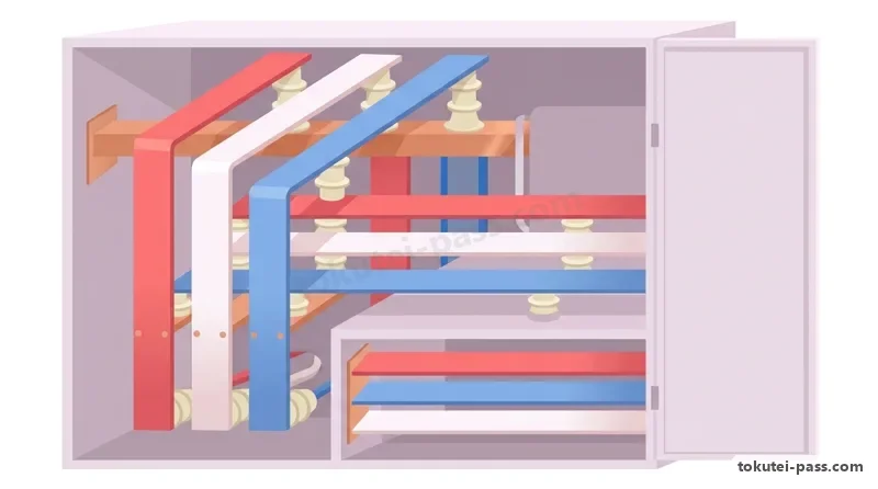
配電盤の主回路導体(母線・ブスバー)には、導電率と機械的強度が高い「硬銅バー(タフピッチ銅C1100)」や「アルミニウムバー」が用いられます。大電流母線は短絡時に強大な電磁力を受けるため、「支持がいし」等で強固に固定します。
Main circuit conductors (busbars) in switchboards use 'hard-drawn copper bars (tough-pitch copper C1100)' or 'aluminum bars' having high electrical conductivity and mechanical strength. Because heavy-current busbars experience strong electromagnetic forces during short circuits, they are firmly supported on 'post insulators (Shiji-gaishi)'.
JEM 1134およびJEM 1425による三相交流母線の相別表示色は、「第1相(R/L1)=赤」「第2相(S/L2)=白」「第3相(T/L3)=青」、中性相(N)=「黒または白」です。単相3線式では「第1相=赤、中性相=白(または黒)、第2相=青」、直流では「正極P=赤、負極N=青」です。
According to JEM 1134 and JEM 1425, the phase identification colors for 3-phase AC busbars are 'Phase 1 (R/L1) = Red', 'Phase 2 (S/L2) = White', 'Phase 3 (T/L3) = Blue', and Neutral (N) = 'Black or White'. For 1-phase 3-wire systems, 'Phase 1 = Red, Neutral = White (or Black), Phase 2 = Blue'; for DC, 'Positive P = Red, Negative N = Blue'.
母線の配置順序は、盤正面(操作装置側)から見て、左右配置は「左から」、上下配置は「上から」、遠近配置は「近い方(手前)から」順に「第1相(赤)→第2相(白)→第3相(青)→中性相」とします。「右から」とする記述は誤りです。
Viewed from the front of the panel (operating side), the busbar phase arrangement order is 'from left to right' for horizontal layout, 'from top to bottom' for vertical layout, and 'from front (nearest) to back' for front-to-back layout in the sequence 'Phase 1 (Red) → Phase 2 (White) → Phase 3 (Blue) → Neutral'. Statements specifying 'from the right' are incorrect.
母線接続部の接触抵抗を減らすため、接合面は平滑に仕上げて「すずめっき」や「銀めっき」を施し(接触面の塗装や酸化皮膜は不可)、原則として母線幅と同じ長さだけ重ね合わせます。
To reduce contact resistance at busbar joints, the mating surfaces are finished flat and smooth, plated with 'tin' or 'silver' (paint or oxide film on contact surfaces is prohibited), and overlapped by a length equal to the busbar width in principle.
ボルト締結は「ボルト頭→平座金→母線→平座金→ばね座金→ナット」の順に通し、トルクレンチで対角線順に規定トルクで締めます。その後「すきまゲージ」で密着を確かめ、ナットから母線面へ「合いマーク」を引いて緩みを管理します。
Bolted busbar joints are assembled in the order 'Bolt head → Plain washer → Busbars → Plain washer → Spring washer → Nut' and tightened diagonally to the specified torque using a torque wrench. Contact tightness is then checked with a 'feeler gauge (thickness gauge)', and a 'torque match-mark (Ai-mark)' is drawn across the nut and busbar.
Key points
- 三相母線の色別は「第1相=赤・第2相=白・第3相=青」であり、正面から見て「左から・上から・近い方から」の順に並べる
Three-phase busbar colors are 'Phase 1 = Red, Phase 2 = White, Phase 3 = Blue', arranged 'from left, from top, and from front' when viewed from the panel front - 母線接合面は接触抵抗を小さくするため平滑にし、「すずめっき」または「銀めっき」を施して重ね合わせる
Busbar joint surfaces must be smooth and 'tin-plated or silver-plated' to minimize contact resistance - 締結後は「トルクレンチ」で規定締付けトルクを確認し、ナットから母線面にかけて「合いマーク」を付けて緩みを管理する
Tighten bolts with a 'torque wrench', verify contact with a feeler gauge, and apply a 'match-mark (Ai-mark)' to monitor against loosening
| Word | Meaning |
|---|---|
| 母線の相別色(赤・白・青)と配置(左・上・手前から) | busbar phase colors (Red, White, Blue) and arrangement (from left, top, front) |
| 接触抵抗の低減(すずめっき・銀めっき) | contact resistance reduction (tin plating, silver plating) |
| トルクレンチと合いマーク | torque wrench and match-mark (Ai-mark) |
| すきまゲージ(接合面の密着確認) | feeler gauge (checking joint surface contact) |
盤内低圧配線の色別・シールド線の色別と電線最小断面積(JEM 1134)
Color Coding of Low-Voltage Panel Wiring, Shielded Wire Colors, and Minimum Conductor Size (JEM 1134)
JEM 1134(配電盤・制御盤の配線用電線の色別)では、回路ごとに電線被覆の標準色が定められています。①「交流・直流の主回路」は「黒色」、②「交流制御回路」は「黄色」、③「直流制御回路」は「青色」、④「接地回路(保護導体)」は「緑色または緑/黄のしま模様」です。
JEM 1134 specifies standard insulation colors for low-voltage panel wiring by circuit type: (1) 'AC and DC main circuits' use 'Black', (2) 'AC control circuits' use 'Yellow', (3) 'DC control circuits' use 'Blue', and (4) 'grounding circuits (protective conductors)' use 'Green or Green/Yellow stripes'.
計器用変成器の二次側回路では、変流器(CT)二次電流回路に「黒色」、計器用変圧器(VT)二次電圧回路に「赤色」を用います。学科試験では「接地回路を青色または黒色とする」という誤りの選択肢が頻出するため注意します。
In instrument transformer secondary circuits, current transformer (CT) secondary current circuits use 'Black' and voltage transformer (VT) secondary voltage circuits use 'Red'. Exam questions frequently include false distractors stating that grounding circuits use blue or black wire.
微弱信号回路に用いる「シールド線(遮へい付き電線)」の色別は、外被(シース)を「灰色または黒色」とし、内部の絶縁線心の色は「単心(1心)=黒」「2心=黒および白」「3心=黒・白および赤」と規定されています(1心の絶縁体を灰色とするのは誤りです)。
For 'shielded wire' used in weak-signal circuits, the outer sheath color is 'Gray or Black', and the inner core insulation colors are specified as 'single-core = Black', '2-core = Black and White', and '3-core = Black, White, and Red' (stating that a single-core shielded wire has gray core insulation is incorrect).
盤内配線の公称断面積は、機械的強度を保つため一般制御回路で「1.25mm²以上」、計器用変成器(CT・VT)二次回路および接地線で「2.0mm²以上」を原則とします。
To ensure mechanical strength, the nominal cross-sectional area of panel wiring is in principle '1.25 mm² or more' for general control circuits, and '2.0 mm² or more' for instrument transformer (CT/VT) secondary circuits and grounding conductors.
ただし近年は、PLCや電子部品などの「使用機器・器具の小形化と高密度実装化」に伴い、使用電圧600V以下の電子制御回路等では0.75mm²や0.5mm²などの「1.25mm²未満」の電線も多く使われています(盤の大形化が理由ではありません)。
In recent years, however, due to the 'miniaturization and high-density mounting of electronic devices and components' such as PLCs, wires smaller than 1.25 mm² (such as 0.75 mm² or 0.5 mm²) are increasingly used in electronic control circuits of 600 V or less (not because panels have become larger).
Key points
- JEM 1134の電線色別は「主回路=黒」「交流制御回路=黄」「直流制御回路=青」「接地回路=緑(または緑/黄)」である
JEM 1134 wire colors are 'Main circuit = Black', 'AC control = Yellow', 'DC control = Blue', and 'Grounding = Green (or Green/Yellow)' - シールド線の外被は「灰または黒」、内部の絶縁被覆は「1心=黒、2心=黒・白、3心=黒・白・赤」である
Shielded wire outer sheaths are 'Gray or Black', while inner core insulations are '1-core = Black, 2-core = Black/White, 3-core = Black/White/Red' - 制御回路は原則「1.25mm²以上」(CT・VT二次側は2mm²以上)だが、機器の「小形化・高密度化」により1.25mm²未満も使われる
Control circuits use '1.25 mm² or more' in principle (CT/VT secondary ≥ 2 mm²), but '< 1.25 mm²' is also used due to 'device miniaturization and high-density mounting'
| Word | Meaning |
|---|---|
| 盤内配線の色別(黒・黄・青・緑) | panel wiring color coding (Black, Yellow, Blue, Green) |
| シールド線の心線色(1心=黒・2心=黒白) | shielded wire core colors (1-core = Black, 2-core = Black & White) |
| 制御回路電線(原則1.25mm²以上) | control circuit wire size (in principle 1.25 mm² or more) |
| 計器用変成器二次配線(2.0mm²以上) | instrument transformer secondary wiring (2.0 mm² or more) |
圧着端子(JIS C 2805)・手動圧着工具の使い方と鉛フリーはんだ付け
Crimp Terminals (JIS C 2805), Proper Use of Hand Crimping Tools, and Lead-Free Soldering
銅線用裸圧着端子(JIS C 2805)には、ねじが緩んでも外れない「丸形1つ穴(R形)」「丸形2つ穴(RD形)」と、ねじを仮緩めした状態で差し込める「先開形(Y形)」があります。主回路・CT二次回路・接地線には安全上必ず丸形(R形・RD形)を用います。
Non-insulated crimp terminals for copper wires (JIS C 2805) include 'ring tongue 1-hole (R-type)', 'ring tongue 2-hole (RD-type)' which cannot slip off even if the screw loosens slightly, and 'fork tongue (Y-type)' which can be inserted under a loosened screw. Ring terminals (R or RD) must be used for main circuits, CT secondary circuits, and grounding wires.
圧着端子の呼び「R 5.5-4」の「5.5」は適用電線の公称断面積5.5mm²(範囲2.63〜6.64mm²)、「4」は取付けねじの呼び「M4(穴径4.3mm)」を表します。絶縁被覆付圧着端子の絶縁体標準色は「1.25mm²用=赤」「2mm²用(2-3.5や2-4)=青」「3.5〜5.5mm²用=黄」です。
In the terminal designation 'R 5.5-4', '5.5' indicates a nominal conductor cross-section of 5.5 mm² (applicable range 2.63–6.64 mm²) and '4' indicates an 'M4 mounting screw (hole diameter 4.3 mm)'. Standard insulation sleeve colors for insulated crimp terminals are 'Red for 1.25 mm²', 'Blue for 2 mm² (e.g., 2-3.5 or 2-4)', and 'Yellow for 3.5–5.5 mm²'.
電線被覆はワイヤストリッパで素線に傷をつけないよう所定長さだけむき、端子の電線抱合部から芯線先端が「約1〜2mm」出るように差し込みます(芯線が全く出ないものや長すぎるものは不良です)。
Strip the wire insulation to the proper length using a wire stripper without nicking or cutting the copper strands, and insert the conductor so the bare wire tip protrudes 'about 1 to 2 mm' beyond the terminal barrel (zero protrusion or excessive protrusion is defective).
手動圧着工具(JIS C 9711、裸端子用は赤柄)では必ず端子サイズに合ったダイスを選び、ラチェット機構が解除されるまで握り切ります。圧着後は「圧着マーク(1.25または○、2、5.5)」と圧縮高さ(クリンプハイト)を確認します。
Using a manual crimping tool (JIS C 9711, red handles for bare terminals), select the die matching the terminal size and squeeze the handles fully until the ratchet mechanism releases. After crimping, inspect the 'crimp mark (1.25 or ○, 2, 5.5)' and the crimp height.
コネクタや基板接続に使う「鉛フリーはんだ(スズ・銀・銅系)」は、従来のすず・鉛はんだ(融点183℃)に比べて「融点が高く(約217〜220℃)、ぬれ性がやや劣り、表面に引け巣ができやすい」特徴があります。フラックスは酸化皮膜を除去してぬれ性を高めます。
Compared to conventional tin-lead eutectic solder (melting point 183°C), 'lead-free solder (Sn-Ag-Cu system)' used for connectors and PCBs has a 'higher melting point (approx. 217–220°C), slightly lower wettability (spreadability), a less glossy appearance, and is more prone to shrinkage cavities'. Flux removes surface oxide films to improve wetting.

Key points
- 圧着端子「R 5.5-4」は5.5mm²電線・M4ねじ用の丸形端子であり、2つ穴丸形は「RD」、絶縁被覆色は「1.25=赤・2=青・5.5=黄」である
Terminal 'R 5.5-4' fits a 5.5 mm² wire and M4 screw; 2-hole ring terminals are 'RD'; standard insulation sleeve colors are '1.25 = Red, 2 = Blue, 5.5 = Yellow' - 適合ダイスの圧着工具(ラチェット機構付き)で最後まで握り込んで圧着し、芯線先端の突出(1〜2mm)・圧着マーク・クリンプハイトを確認する
Squeeze the ratcheting crimping tool fully in the matching die, then verify wire tip protrusion (1–2 mm), the crimp mark, and crimp height - 鉛フリーはんだは従来の鉛入りはんだより「溶融温度(融点)が高く、ぬれ性が劣る」ため、フラックスで酸化膜を除去して適切に加熱する
Lead-free solder has a 'higher melting temperature and lower wettability' than lead solder, requiring proper heating with flux to remove oxides
| Word | Meaning |
|---|---|
| 丸形圧着端子(R形・RD形)と先開形(Y形) | ring crimp terminals (R-type, RD-type) and fork terminals (Y-type) |
| 絶縁体の標準色(赤1.25・青2・黄5.5) | standard insulation sleeve colors (Red 1.25, Blue 2, Yellow 5.5) |
| ラチェット機構とクリンプハイト | ratchet mechanism and crimp height |
| 鉛フリーはんだとフラックス | lead-free solder and flux |
ダクト配線・束配線・端子台接続・扉渡り配線とノイズ分離対策
Duct Wiring, Bundle Wiring, Terminal Block Connections, Door Crossover Wiring, and Noise Separation
盤内の配線方式には、合成樹脂製ダクトに電線を収める「ダクト配線方式」と、結束バンド等で整列して束ねる「束配線方式」があり、1つの盤内で両方式を併用することもできます。ダクトは「ダクトカッタ」でバリが出ないよう直角に切断します。
Internal panel wiring methods include 'duct wiring', where wires are housed in slotted synthetic resin ducts, and 'bundle wiring', where wires are neatly aligned and tied with cable ties; both methods are often combined in a single panel. Wiring ducts are cut squarely without burrs using a 'duct cutter'.
JEMの盤内配線規約により、①電線の途中接続は行わず、分岐は必ず「機器端子または端子台」で行うこと、②電線を金属製の押さえ金具で直接強く締め付けないこと(絶縁緩衝材を介する)が定められています。
Under JEM panel wiring rules: (1) mid-wire splices are prohibited and all branches must be made at 'equipment terminals or terminal blocks', and (2) wires must never be clamped directly with bare metal clips without insulating sleeves or cushioning material.
組端子台の1端子の片側に共締めできる圧着端子は「2本以下」とし、2本重ねるときは接触面積と安定性を保つため「裏面同士(背中合わせ)」に合わせて締めます。マークチューブの文字は左から右・上から下へ読める向きに揃えます。
At most '2 crimp terminals' may be fastened together on one side of a terminal block pole, and when stacking 2 terminals they must be placed 'back-to-back (flat undersides facing each other)' to maintain full contact area and stability. Wire mark tubes are oriented to read from left to right and from top to bottom.
固定枠から扉へ渡す「扉渡り配線」では、ヒンジ付近で電線が緩やかな「ねじり」を受けるようU字状のたるみを持たせ、両端をマウントベースと結束バンドで固定して「スパイラルチューブ」で保護します。扉には保護接地用の「アース渡り線」も接続します。
For 'door crossover wiring' bridging from the fixed frame to a hinged door, form a U-shaped loop near the hinge so the bundle undergoes gentle 'twisting' rather than sharp bending when the door opens, secure both ends with mount bases and cable ties, and wrap the bundle in a 'spiral tube'. A protective 'bonding ground wire' must also connect the door to the cabinet.
インバータ出力線や動力主回路からの電磁ノイズがPLCやセンサの信号に混入するのを防ぐため、「主回路と制御回路・信号回路は分離して配線」します。やむを得ず交差させる場合は平行に走らせず「直角に交差」させます。
To prevent electromagnetic noise from inverter outputs or power main circuits from entering PLC or sensor signals, 'main circuits and control/signal circuits must be routed separately'. Where crossing is unavoidable, cross them 'at right angles (perpendicularly)' rather than running them in parallel.
Key points
- 電線の分岐は必ず「端子台または機器端子」で行い、1端子への接続は「2本以下(2本は裏面同士を合わせる)」とする
All wire branches must be made at 'terminal blocks or device terminals', with 'at most 2 terminals per screw (placed back-to-back)' - 電線を金属片で直接締め付けてはならず、扉渡り配線はスパイラルチューブで保護してヒンジ部で余裕を持たせる
Never clamp wires directly with bare metal; protect door crossover wiring with a spiral tube and allow slack for torsion at the hinge - ノイズ防止のため「主回路と制御・信号回路は分離配線」し、交差部は「直角交差」とする
To prevent noise interference, 'separate main circuit wiring from control/signal wiring' and cross them 'at right angles' when necessary
| Word | Meaning |
|---|---|
| ダクト配線方式と束配線方式 | duct wiring method and bundle wiring method |
| 端子台での分岐と裏面同士の共締め(2本以下) | branching at terminal blocks and back-to-back fastening (max 2 terminals) |
| 扉渡り配線とスパイラルチューブ | door crossover wiring and spiral tube |
| 主回路と制御回路の分離配線 | separated wiring of main circuits and control circuits |
計器用変成器(CT・VT)および盤面計器・切替えスイッチの接続法
Connection Methods for Instrument Transformers (CT, VT), Panel Meters, and Changeover Switches
高圧回路や大電流回路の測定・保護には、高電圧を110Vに降圧する「計器用変圧器(VT)」と、大電流を5A(または1A)に変流する「変流器(CT)」を用います。1台の計器で三相各相を測るには電圧計切替えスイッチ(VS)や電流計切替えスイッチ(AS)を使います。
For measuring and protecting high-voltage or heavy-current circuits, a 'voltage transformer (VT)' steps high voltage down to 110 V and a 'current transformer (CT)' steps large current down to 5 A (or 1 A). A voltmeter changeover switch (VS) or ammeter changeover switch (AS) allows a single meter to read all three phases.
変流器(CT)の一次側に通電中は、二次側回路を絶対に「開放(オープン)」してはいけません。二次側を開放すると鉄心磁束が飽和して二次端子に数千Vの異常高電圧が発生し、絶縁破壊や焼損・感電事故を招きます。
While current is flowing in the primary winding of a current transformer (CT), its secondary circuit must 'never be open-circuited'. Opening the secondary saturates the core magnetic flux and induces a dangerous high voltage of several thousand volts across the secondary terminals, causing insulation breakdown, burnout, or electric shock.
そのためCT二次回路には「ヒューズを取り付けてはならず」、電流計切替えスイッチASには切替中も二次回路が開放されない「ショーティング(短絡)接点」や短絡片付き試験用端子台(テストターミナル)を用います。
Consequently, 'fuses must never be installed in a CT secondary circuit', and an ammeter changeover switch (AS) must use 'make-before-break (shorting) contacts' along with a shorting-bar test terminal block so the secondary circuit is never opened during switching or meter replacement.
一方、計器用変圧器(VT)の二次側は短絡すると焼損するため保護用ヒューズを設けます。また高低圧混触による危険を防ぐため、電気設備技術基準の解釈により「高圧用VT・CTの二次側電路にはD種接地工事」、「特別高圧用VT・CTの二次側電路にはA種接地工事」を施します。
Conversely, a voltage transformer (VT) secondary will burn out if short-circuited, so protective fuses are installed. To prevent shock hazards from high-to-low voltage contact, the Interpretation of Technical Standards for Electrical Equipment requires 'Class D grounding on the secondary circuit of high-voltage VTs/CTs' and 'Class A grounding on the secondary of extra-high-voltage VTs/CTs'.
盤面の指示計器において、電流計は内部抵抗が極めて小さいため負荷と「直列」に、電圧計は内部抵抗が極めて大きいため負荷と「並列」に接続します。電力計や力率計は電流コイルを直列・電圧コイルを並列に接続します。
Among panel indicating meters, an ammeter has a very low internal resistance and is connected in 'series' with the load, whereas a voltmeter has a very high internal resistance and is connected in 'parallel' with the load. Wattmeters and power factor meters have their current coil connected in series and voltage coil in parallel.
Key points
- 変流器(CT)の二次側は通電中に開放すると高電圧が発生して危険なため、「CT二次回路にヒューズを入れてはならない」
Opening a live CT secondary generates hazardous high voltage; therefore, 'never install fuses in a CT secondary circuit' - 電気設備技術基準の解釈により、高圧VT・CTの二次側電路には「D種接地工事」、特別高圧VT・CTの二次側には「A種接地工事」を施す
Under the Technical Standards Interpretation, apply 'Class D grounding' to high-voltage VT/CT secondaries and 'Class A grounding' to extra-high-voltage VT/CT secondaries - 電流計は内部抵抗が小さく回路に「直列」、電圧計は内部抵抗が大きく回路に「並列」に接続する
Connect ammeters (low internal resistance) in 'series' with the circuit and voltmeters (high internal resistance) in 'parallel'
| Word | Meaning |
|---|---|
| 変流器(CT)二次開放禁止とヒューズ禁止 | prohibition of open-circuiting and fusing CT secondary circuits |
| 計器用変圧器(VT)とD種・A種接地工事 | voltage transformer (VT) and Class D / Class A grounding |
| 電流計切替えスイッチ(AS)と電圧計切替えスイッチ(VS) | ammeter changeover switch (AS) and voltmeter changeover switch (VS) |
| 電流計・電圧計の内部抵抗 | internal resistance of ammeters and voltmeters |
配電盤・制御盤の試験検査(標準状態・受渡試験・絶縁抵抗・耐電圧試験)
Testing and Inspection of Switchboards and Control Panels (Standard Conditions, Acceptance Tests, Insulation & Withstand Voltage)
JEM 1425における工場試験場所の「標準状態」は、①「周囲温度 20±15℃(5〜35℃)」、②「相対湿度 45〜85%」、③「気圧 86〜106kPa」の3項目と定められています(「振動」や「騒音」を含めたり、「温度25±2℃」としたりする記述は誤りです)。
In JEM 1425, the 'standard ambient conditions' for factory testing locations are defined by three parameters: (1) 'ambient temperature 20 ± 15°C (5–35°C)', (2) 'relative humidity 45–85%', and (3) 'atmospheric pressure 86–106 kPa' (exam choices including 'vibration' or 'noise' or stating '25 ± 2°C' are incorrect).
盤の試験には、新設計時に代表品で行う「形式試験」と、製作した全数を出荷時に行う「受渡試験」があります。受渡試験は「①外観・構造試験」「②シーケンス試験(機能動作試験)」「③絶縁抵抗試験」「④耐電圧試験」の4項目であり、「温度上昇試験」は含まれません。
Panel tests include 'type tests (Keishiki shiken)' performed on representative units for new designs and 'acceptance/routine tests (Ukewatashi shiken)' performed on every completed panel before delivery. The 4 acceptance test items are '(1) visual and structural inspection', '(2) sequence (functional operation) test', '(3) insulation resistance test', and '(4) dielectric withstand voltage test'; the 'temperature rise test' is a type test and is not part of acceptance testing.
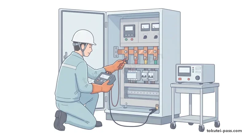
「絶縁抵抗試験」では絶縁抵抗計(メガー、低圧盤は通常500Vメガー)を用い、充電部一括と接地金属箱間の絶縁抵抗を測定します。PLC・インバータ・半導体素子等は高電圧で破損するため、試験前に端子を「取り外すか一括短絡」して保護します。
In the 'insulation resistance test', an insulation resistance tester (Megger, typically 500 V for low-voltage panels) measures resistance between all live parts connected together and the grounded metal enclosure. Because PLCs, inverters, and semiconductor elements can be damaged by high test voltages, their terminals must be 'disconnected orjumpered together' beforehand.
「商用周波耐電圧試験」では、規定の交流試験電圧を「1分間」印加して異常がないことを確認します。低圧回路の試験電圧は、定格絶縁電圧が「60Vを超え250V以下(100V・200V回路)で1500V」、「250Vを超え600V以下(400V回路)で2000V」です。
In the 'power-frequency withstand voltage test', the specified AC test voltage is applied for '1 minute' to verify that no insulation breakdown occurs. For low-voltage circuits, the test voltage is '1500 V for rated insulation voltages over 60 V up to 250 V (100 V / 200 V circuits)' and '2000 V for over 250 V up to 600 V (400 V circuits)'.
また6.6kVキュービクル式高圧受電設備(JIS C 4620)の高圧主回路(定格電圧7.2kV)における対地間・相間の試験電圧は、商用周波耐電圧試験が「16000V(16kV)・1分間」、衝撃電圧(インパルス耐電圧試験)が「60kV」と定められています。
For the high-voltage main circuit (rated voltage 7.2 kV) of 6.6 kV cubicle-type high-voltage receiving equipment (JIS C 4620), the phase-to-ground and phase-to-phase test voltages are specified as '16000 V (16 kV) for 1 minute' at power frequency and '60 kV' for the lightning impulse withstand voltage test.
Key points
- 試験場所の標準状態は「温度20±15℃・相対湿度45〜85%・気圧86〜106kPa」であり、振動や騒音は含まれない
Standard test room conditions are 'temperature 20 ± 15°C, relative humidity 45–85%, and pressure 86–106 kPa' (excluding vibration and noise) - 受渡試験は「外観構造・シーケンス・絶縁抵抗・耐電圧」の4試験であり、「温度上昇試験」は含まれない
Acceptance tests consist of 4 items: 'Visual/structural, Sequence, Insulation resistance, and Withstand voltage'; 'Temperature rise test' is excluded - 1分間の商用周波耐電圧試験は、定格絶縁電圧「60V超〜250V以下=1500V」「250V超〜600V以下=2000V」「6.6kVキュービクル主回路=16000V」で行う
The 1-minute power-frequency withstand voltage test uses '1500 V for >60 V to 250 V', '2000 V for >250 V to 600 V', and '16000 V for 6.6 kV cubicle main circuits'
| Word | Meaning |
|---|---|
| 試験場所の標準状態(20±15℃・45〜85%・86〜106kPa) | standard test room conditions (20±15°C, 45–85%, 86–106 kPa) |
| 受渡試験と形式試験(温度上昇試験) | acceptance test and type test (temperature rise test) |
| 絶縁抵抗試験(メガー) | insulation resistance test (Megger) |
| 商用周波耐電圧試験(1500V・2000V・16000Vを1分間) | power-frequency withstand voltage test (1500 V, 2000 V, 16000 V for 1 minute) |
Switchboard & Control Panel Assembly
Practice this chapter in the appOfficial references
- 中央職業能力開発協会(JAVADA)「技能検定 電気機器組立て(配電盤・制御盤組立て作業)2級 学科試験公表問題」 — https://www.javada.or.jp/jigyou/gino/giken.html
- 日本産業規格「JIS C 8480 キャビネット形動力制御盤」「JIS C 0448 指示電気計器及び補助品の端子記号」 — https://www.jisc.go.jp/