
Fundamentals of Electrical Theory, Electronic Circuits, and Automatic Control (DC, AC, Electromagnetism, Semiconductors, Logic Circuits, Control)
電気理論・電子回路・自動制御の基礎(直流・交流・電磁気・半導体・論理回路・制御)
Electrical Equipment Assembly – Control Panels 電気機器組立て (Grade 2 theory) · 技能検定「電気機器組立て」2級 学科(配電盤・制御盤組立て) · Written by Tokutei Pass based on the official study texts; not copied verbatim.
オームの法則・キルヒホッフの法則・直並列合成抵抗とホイートストンブリッジ
Ohm's Law, Kirchhoff's Laws, Series-Parallel Equivalent Resistance, and Wheatstone Bridge
導体に流れる電流 I(A)は加えた電圧 V(V)に比例し、電気抵抗 R(Ω)に反比例します。これを「オームの法則(I = V ÷ R、V = I × R)」といい、一定の抵抗に流れる電流は電圧に比例して増加します。
The current I (A) flowing through a conductor is proportional to the applied voltage V (V) and inversely proportional to the electrical resistance R (Ω). This is called "Ohm's law (I = V ÷ R, V = I × R)", meaning current through a constant resistance increases in proportion to voltage.
複雑な回路網の計算には「キルヒホッフの法則」を用います。第1法則(電流則)は「回路内の任意の接続点に流入する電流の和と流出する電流の和は等しい」、第2法則(電圧則)は「閉回路における起電力の和と電圧降下の和は等しい」という法則です。
"Kirchhoff's laws" are used to calculate complex circuit networks. The 1st law (current law) states that "the sum of currents flowing into any node in a circuit equals the sum of currents flowing out"; the 2nd law (voltage law) states that "the sum of electromotive forces in a closed loop equals the sum of voltage drops".
複数の抵抗を直列接続した合成抵抗は「R = R1 + R2」となり、各抵抗には抵抗値に比例した電圧が分圧されます。一方、並列接続の合成抵抗は「R =(R1 × R2)÷(R1 + R2)」(和分の積)となり、各枝路には抵抗値の逆比で電流が分流します。
The equivalent resistance of multiple resistors in series is "R = R1 + R2", dividing voltage in proportion to resistance values. Conversely, the equivalent resistance of two resistors in parallel is "R = (R1 × R2) ÷ (R1 + R2)" (product over sum), dividing current in inverse proportion to branch resistances.
例えば6Ωと3Ωの並列回路(合成 2Ω)に8Ωの抵抗を直列につないで100Vを加えると、全体の合成抵抗は「2 + 8 = 10Ω」、全体電流は「100 ÷ 10 = 10A」となり、並列部の6Ω側には「10A × 3 ÷(6 + 3)= 3.33A」が流れます。
For example, when an 8Ω resistor is connected in series with a parallel circuit of 6Ω and 3Ω (equivalent to 2Ω) across 100V, total equivalent resistance is "2 + 8 = 10Ω", total current is "100 ÷ 10 = 10A", and "10A × 3 ÷ (6 + 3) = 3.33A" flows through the 6Ω branch.
また未知の抵抗を精密測定する「ホイートストンブリッジ回路」では、中央の検流計Gに電流が流れない平衡状態のとき、向かい合う辺の抵抗の積が等しくなる「R1 × R4 = R2 × R3」が成り立ちます(例:10Ω × 6Ω = 20Ω × R より R = 3Ω)。
Furthermore, in a "Wheatstone bridge circuit" for precision measurement of an unknown resistance, when balanced (zero current through the central galvanometer G), the products of opposite arm resistances are equal: "R1 × R4 = R2 × R3" (e.g., 10Ω × 6Ω = 20Ω × R gives R = 3Ω).
Key points
- オームの法則により電流は「I = V ÷ R」で表され、抵抗が一定なら電流は電圧に比例する
By Ohm's law, current is expressed as "I = V ÷ R", increasing proportionally to voltage when resistance is constant - 2個の抵抗の並列合成抵抗は「R =(R1 × R2)÷(R1 + R2)」で求め、直並列回路は並列部から順に合成する
Parallel equivalent resistance of 2 resistors is "R = (R1 × R2) ÷ (R1 + R2)", and series-parallel circuits are combined starting from the parallel section - ホイートストンブリッジが平衡(検流計の電流が0)のとき、対辺の積「R1 × R4 = R2 × R3」が成り立つ
When a Wheatstone bridge is balanced (galvanometer current is 0), the product of opposite arms "R1 × R4 = R2 × R3" holds
| Word | Meaning |
|---|---|
| オームの法則(V = I × R) | Ohm's law (V = I × R) |
| キルヒホッフの第1法則・第2法則 | Kirchhoff's 1st law and 2nd law |
| 直並列合成抵抗と分圧・分流 | Series-parallel equivalent resistance and voltage/current division |
| ホイートストンブリッジの平衡条件 | Wheatstone bridge balance condition |
導体の電気抵抗(長さ・断面積・直径の関係)と電力・ジュールの法則
Conductor Resistance (Length, Cross-Sectional Area, and Diameter) and Power / Joule's Law
電線などの導体の電気抵抗 R(Ω)は、材料固有の「抵抗率」と導体の「長さ l(m)」に比例し、導体の「断面積 A(mm²)」に反比例します。また丸線の断面積 A は「直径 d の2乗(d²)」に比例します。
The electrical resistance R (Ω) of a conductor such as a wire is proportional to the material's inherent "resistivity" and conductor "length l (m)", and inversely proportional to its "cross-sectional area A (mm²)". Also, the cross-sectional area A of a round wire is proportional to the "square of its diameter d (d²)".
したがって、丸線の直径 d が「2倍」になると断面積 A は「2² = 4倍」になり、単位長あたりの電気抵抗は「1/4(4分の1)」に減ります。逆に、直径1mm・長さ1mの銅線と同じ抵抗値を直径2mm(断面積4倍)の銅線で得るには、長さを4倍の「4m」にする必要があります。
Therefore, doubling the diameter d of a round wire increases its cross-sectional area A by "2² = 4 times", reducing resistance per unit length to "1/4 (one-fourth)". Conversely, to obtain the same resistance as a 1mm-diameter, 1m-long copper wire using a 2mm-diameter copper wire (4 times the area), the length must be quadrupled to "4m".
純金属(銅やアルミニウムなど)の電気抵抗は、温度が上昇すると増加する「正の抵抗温度係数」を持ちます。一方、炭素(カーボン)や半導体(サーミスタなど)は温度が上がると抵抗が減少する性質があります。
The electrical resistance of pure metals (such as copper and aluminum) has a "positive temperature coefficient of resistance", increasing as temperature rises. Conversely, carbon and semiconductors (such as thermistors) exhibit decreasing resistance as temperature rises.
直流回路で1秒間に消費される電力 P(単位:W)は「P = V × I = I² × R = V² ÷ R」で求められ、電力 P(W)に時間 t(h)を掛けたものを電力量 W(WhまたはkWh)といいます。
Power P (unit: W) consumed per second in a DC circuit is found by "P = V × I = I² × R = V² ÷ R", and multiplying power P (W) by time t (h) gives electrical energy W (Wh or kWh).
抵抗 R(Ω)に電流 I(A)を t 秒間流したときに発生する熱量(ジュール熱)Q(単位:J)は、「ジュールの法則」により「Q = P × t = I² × R × t[J]」となります(1 W・s = 1 J であり、1 kWh = 3600 kJ に相当します)。
The heat (Joule heat) Q (unit: J) generated when current I (A) flows through resistance R (Ω) for t seconds is given by "Joule's law" as "Q = P × t = I² × R × t (J)" (1 W·s = 1 J, and 1 kWh equals 3600 kJ).
Key points
- 導体の抵抗は長さに比例し断面積(直径の2乗)に反比例するため、直径2倍の電線で同じ抵抗にするには長さを「4倍」にする
Conductor resistance is proportional to length and inversely proportional to cross-sectional area (square of diameter), so a wire with twice the diameter requires "4 times" the length for equal resistance - 銅やアルミなどの金属導体は、温度が上がると電気抵抗が増加する(正の温度係数)
Metallic conductors like copper and aluminum increase in electrical resistance as temperature rises (positive temperature coefficient) - ジュールの法則により、電流による発熱量は「Q = I² × R × t[J]」となり電流の2乗に比例する
By Joule's law, heat generated by current is "Q = I² × R × t (J)", proportional to the square of the current
| Word | Meaning |
|---|---|
| 抵抗率と導体の長さ・断面積(直径の2乗) | Resistivity and conductor length / cross-sectional area (square of diameter) |
| 抵抗温度係数(金属は温度上昇で抵抗増) | Temperature coefficient of resistance (metals increase in resistance as temperature rises) |
| 電力(W)と電力量(Wh・kWh) | Electric power (W) and electrical energy (Wh, kWh) |
| ジュールの法則(Q = I² × R × t[J]) | Joule's law (Q = I² × R × t (J)) |
静電気とコンデンサの静電容量・直並列合成容量・蓄えられるエネルギー
Electrostatics and Capacitor Capacitance, Series-Parallel Equivalent Capacitance, and Stored Energy
帯電した2つの電荷の間に働く静電力は、電荷の積に比例し距離の2乗に反比例します(クーロンの法則)。2枚の金属極板の間に誘電体(絶縁物)を挟んだ「コンデンサ」の静電容量 C(単位:F または μF)は、誘電率と極板面積 S に比例し、極板間距離 d に反比例します。
The electrostatic force between two electric charges is proportional to the product of the charges and inversely proportional to the square of the distance (Coulomb's law). The capacitance C (unit: F or μF) of a "capacitor" with a dielectric (insulator) between two metal plates is proportional to permittivity and plate area S, and inversely proportional to plate separation d.
静電容量 C(F)のコンデンサに電圧 V(V)を加えたときに蓄えられる電荷(電気量)Q(C:クーロン)は「Q = C × V」であり、蓄えられる静電エネルギー W(J)は「W = 0.5 × C × V²」で表されます。
When voltage V (V) is applied to a capacitor of capacitance C (F), the stored electric charge Q (C: coulomb) is "Q = C × V", and the stored electrostatic energy W (J) is expressed as "W = 0.5 × C × V²".
複数のコンデンサを「並列接続」したときの合成静電容量 C は、極板面積が増えるのと同じため各容量の単純な和「C = C1 + C2 + C3」となります(抵抗の直並列の公式と逆になる点に注意します)。
When multiple capacitors are connected in "parallel", the equivalent capacitance C is the simple sum of each capacitance, "C = C1 + C2 + C3", just like increasing plate area (note that this is opposite to the series-parallel formulas for resistors).
一方、コンデンサを「直列接続」したときの合成静電容量 C は逆数の和「1/C = 1/C1 + 1/C2 + 1/C3」から求めます。2個直列なら「C =(C1 × C2)÷(C1 + C2)」、3個直列なら「C =(C1 × C2 × C3)÷(C1×C2 + C2×C3 + C3×C1)」となります。
Conversely, when capacitors are connected in "series", the equivalent capacitance C is found from the sum of reciprocals "1/C = 1/C1 + 1/C2 + 1/C3". For 2 in series, "C = (C1 × C2) ÷ (C1 + C2)", and for 3 in series, "C = (C1 × C2 × C3) ÷ (C1×C2 + C2×C3 + C3×C1)".
またコンデンサを直列接続して電圧を加えると、各コンデンサに蓄えられる電荷 Q は等しくなり、各コンデンサに分圧される電圧は「静電容量 C に反比例」します(容量が小さいコンデンサほど高い電圧がかかります)。
Furthermore, when voltage is applied across series-connected capacitors, the stored charge Q on each capacitor is equal, and the voltage divided across each capacitor is "inversely proportional to its capacitance C" (smaller-capacitance capacitors bear higher voltage).
Key points
- コンデンサの電荷は「Q = C × V」、エネルギーは「W = 0.5 × C × V²」であり、静電容量は面積に比例し極板間隔に反比例する
Capacitor charge is "Q = C × V", energy is "W = 0.5 × C × V²", and capacitance is proportional to area and inversely proportional to plate spacing - コンデンサの並列合成容量は「C = C1 + C2 + C3」、直列合成容量は逆数の和「1/C = 1/C1 + 1/C2 + 1/C3」となる
Parallel equivalent capacitance is "C = C1 + C2 + C3", and series equivalent capacitance is the reciprocal sum "1/C = 1/C1 + 1/C2 + 1/C3" - 3個のコンデンサ C1・C2・C3 の直列合成容量は「(C1 × C2 × C3)÷(C1×C2 + C2×C3 + C3×C1)」で表される
The series equivalent capacitance of 3 capacitors C1, C2, C3 is expressed as "(C1 × C2 × C3) ÷ (C1×C2 + C2×C3 + C3×C1)"
| Word | Meaning |
|---|---|
| クーロンの法則と静電容量(C) | Coulomb's law and capacitance (C) |
| 電荷(Q = C × V)と静電エネルギー | Electric charge (Q = C × V) and electrostatic energy |
| コンデンサの並列合成容量と直列合成容量 | Parallel and series equivalent capacitance of capacitors |
| コンデンサ直列接続時の逆比例分圧 | Inverse-proportion voltage division in series capacitors |
電流の磁気作用・フレミングの左手の法則と右手の法則・レンツの法則
Magnetic Effect of Current, Fleming's Left-Hand and Right-Hand Rules, and Lenz's Law
導線に電流を流すと、その周囲に右ねじを進める向きの回転方向に磁界が発生します。これを「アンペアの右ねじの法則(右ねじの法則)」といい、ソレノイド(コイル)に電流を流したときの磁極(N極・S極)の向きもこの法則で決まります。
Passing current through a wire generates a magnetic field around it in the rotational direction that advances a right-handed screw. This is called "Ampere's right-handed screw rule", which also determines the magnetic poles (N-pole, S-pole) when current flows through a solenoid (coil).
磁界中の導体に電流を流すと電磁力 F(N)が働き、その向きは「フレミングの左手の法則(電動機の原理)」に従います。左手の3指を互いに直角に開いたとき、「中指=電流の向き、人差し指=磁界の向き、親指=電磁力(運動)の向き」を表します。
Passing current through a conductor in a magnetic field exerts an electromagnetic force F (N) whose direction follows "Fleming's left-hand rule (motor principle)". Holding the thumb, forefinger, and middle finger of the left hand mutually perpendicular: "middle finger = current direction, forefinger = magnetic field direction, thumb = electromagnetic force (motion) direction".
逆に、磁界中で導体を動かしたときに発生する誘導起電力 e(V)の向きは「フレミングの右手の法則(発電機の原理)」に従い、右手の「親指=導体の運動方向、人差し指=磁界の向き、中指=誘導起電力の向き」となります。
Conversely, the direction of induced EMF e (V) generated when moving a conductor in a magnetic field follows "Fleming's right-hand rule (generator principle)", where on the right hand: "thumb = conductor motion direction, forefinger = magnetic field direction, middle finger = induced EMF direction".
コイルを貫く磁束が変化するとき、磁束の時間的変化率に比例した大きさの誘導起電力が発生する現象を「ファラデーの電磁誘導の法則」といい、その誘導起電力の向きが「磁束の変化を妨げる方向」になることを「レンツの法則」といいます。
When magnetic flux linking a coil changes, generating an induced EMF proportional to the time rate of change of flux is called "Faraday's law of electromagnetic induction", and the fact that its direction "opposes the change in magnetic flux" is called "Lenz's law".
誘導形電力量計のアルミニウム円板が移動磁界とうず電流の作用で回転し、制動磁石で速度制御される原理などには、この「レンツの法則(電磁誘導作用)」が応用されています。またコイル自身の電流変化で起電力が生じる現象を自己誘導(インダクタンス L[H])といいます。
The principle by which the aluminum disk of an induction watt-hour meter rotates under a moving magnetic field and eddy currents while speed-controlled by a braking magnet applies this "Lenz's law (electromagnetic induction)". Also, EMF induced by a coil's own current change is called self-induction (inductance L (H)).
Key points
- 「フレミングの左手の法則(電動機)」では、中指が電流、人差し指が磁界、親指が電磁力(力)の向きを示す
In "Fleming's left-hand rule (motors)", the middle finger indicates current, the forefinger indicates magnetic field, and the thumb indicates electromagnetic force - 「フレミングの右手の法則(発電機)」では、親指が運動、人差し指が磁界、中指が誘導起電力の向きを示す
In "Fleming's right-hand rule (generators)", the thumb indicates motion, the forefinger indicates magnetic field, and the middle finger indicates induced EMF - 電磁誘導において「磁束の変化を妨げる向き」に誘導電流が流れる法則を「レンツの法則」といい、電力量計の円板回転等に応用される
In electromagnetic induction, the law that induced current flows in a "direction opposing the change in magnetic flux" is called "Lenz's law", applied in watt-hour meter disk rotation
| Word | Meaning |
|---|---|
| アンペアの右ねじの法則 | Ampere's right-handed screw rule |
| フレミングの左手の法則(中指=電流・人差し指=磁界・親指=力) | Fleming's left-hand rule (middle = current, forefinger = magnetic field, thumb = force) |
| フレミングの右手の法則(誘導起電力の向き) | Fleming's right-hand rule (direction of induced EMF) |
| ファラデーの電磁誘導とレンツの法則 | Faraday's electromagnetic induction and Lenz's law |
単相交流回路(実効値・位相差・リアクタンス計算・インピーダンス)
Single-Phase AC Circuits (RMS Value, Phase Difference, Reactance Calculation, Impedance)
サイン波交流の大きさは通常「実効値」で表され、最大値(波高値)Vm は実効値 V の「ルート2倍(約1.41倍)」(V = Vm ÷ 1.41)となります。また1秒間のサイクル数である周波数 f(Hz)と周期 T(s)には「f = 1 ÷ T」の関係があります。
The magnitude of sine-wave AC is normally expressed by its "effective (RMS) value", and the maximum (peak) value Vm is "root-2 times (approx. 1.41 times)" the RMS value V (V = Vm ÷ 1.41). Also, frequency f (Hz)—the number of cycles per second—and period T (s) are related by "f = 1 ÷ T".
交流回路における電圧と電流の位相差は、抵抗 R のみの回路では「同相(位相差 0°)」、コイル(インダクタンス L)のみの回路では「電流が電圧より 90°(π/2 rad)遅れる」、コンデンサ(静電容量 C)のみの回路では「電流が電圧より 90°(π/2 rad)進む」となります。
Regarding phase difference between voltage and current in AC circuits: a pure resistor R circuit is "in phase (0° phase difference)", a pure coil (inductance L) circuit has "current lagging voltage by 90° (π/2 rad)", and a pure capacitor (capacitance C) circuit has "current leading voltage by 90° (π/2 rad)".
コイルの誘導性リアクタンス XL(Ω)は「XL = 2 × π × f × L」で求まります。例えば L = 5 H のコイルに 100V・50Hz を加えると「XL = 2 × 3.14 × 50 × 5 = 1570 Ω」となり、電流は「I = 100 ÷ 1570 = 約0.064 A」が流れます。
Inductive reactance XL (Ω) of a coil is found by "XL = 2 × π × f × L". For example, applying 100V, 50Hz to a coil of L = 5 H gives "XL = 2 × 3.14 × 50 × 5 = 1570 Ω", and a current of "I = 100 ÷ 1570 = approx. 0.064 A" flows.
コンデンサの容量性リアクタンスは「XC = 1 ÷(2 × π × f × C)」です。R・L・C直列回路ではインピーダンス Z の2乗が「Z² = R² +(XL − XC)²」となり、XL = XC のとき「直列共振」が起きてインピーダンスが最小(Z = R)になります。
Capacitive reactance of a capacitor is "XC = 1 ÷ (2 × π × f × C)". In an R-L-C series circuit, the square of impedance Z is "Z² = R² + (XL − XC)²", and when XL = XC, "series resonance" occurs, minimizing impedance (Z = R).
単相交流回路の皮相電力は「S = V × I[VA]」、有効電力(消費電力)は力率 cosφ(= R ÷ Z)を掛けた「P = V × I × cosφ[W]」、無効電力は「Q = V × I × sinφ[var]」となります。
In a single-phase AC circuit, apparent power is "S = V × I (VA)", active power (consumed power) multiplied by power factor cosφ (= R ÷ Z) is "P = V × I × cosφ (W)", and reactive power is "Q = V × I × sinφ (var)".
Key points
- コイル(L)のみの交流回路では電流の位相が電圧より「90°遅れ」、コンデンサ(C)のみの回路では「90°進む」
In a pure coil (L) AC circuit, current phase "lags voltage by 90°", whereas in a pure capacitor (C) circuit it "leads by 90°" - 誘導性リアクタンスは「XL = 2 × π × f × L」であり、50Hz・100Vの電源に L = 5H を接続すると XL = 1570Ω、I = 約0.064A となる
Inductive reactance is "XL = 2 × π × f × L"; connecting L = 5H to a 50Hz, 100V supply gives XL = 1570Ω and I = approx. 0.064A - 直列回路のインピーダンスは「Z² = R² +(XL − XC)²」、力率は「cosφ = R ÷ Z」で表される
Series circuit impedance is "Z² = R² + (XL − XC)²", and power factor is expressed as "cosφ = R ÷ Z"
| Word | Meaning |
|---|---|
| 実効値と最大値(Vm = 1.41 × V) | Effective (RMS) value and maximum value (Vm = 1.41 × V) |
| 位相の遅れ(コイル90°遅れ)と進み(コンデンサ90°進み) | Phase lag (coil lags by 90°) and phase lead (capacitor leads by 90°) |
| 誘導性リアクタンス(XL = 2 × π × f × L) | Inductive reactance (XL = 2 × π × f × L) |
| インピーダンス(Z)と力率(cosφ) | Impedance (Z) and power factor (cosφ) |
三相交流回路(Y結線・△結線)と三相電力の計算・進相コンデンサ
Three-Phase AC Circuits (Y and △ Connections), Three-Phase Power Calculation, and Power Capacitors
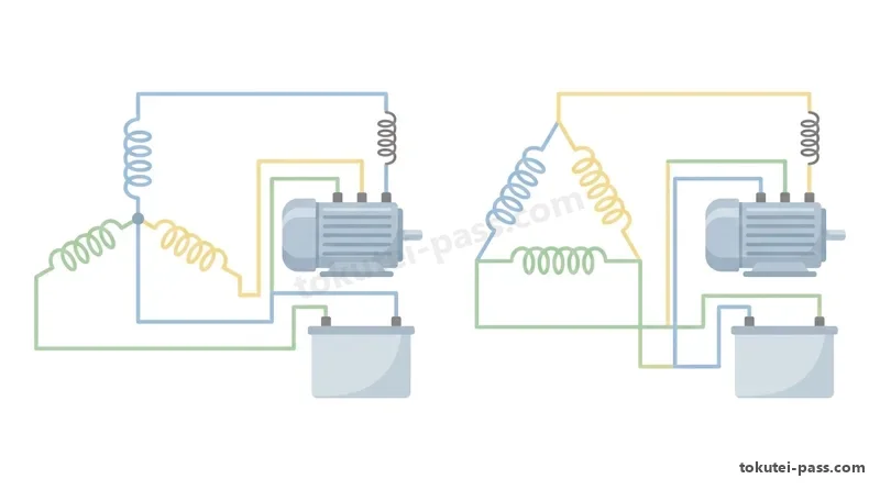
対称三相交流は、大きさと周波数が等しい3つの単相交流起電力が互いに「120°(2π/3 rad)」ずつ位相がずれた交流です。結線方式には「スター(Y)結線」と「デルタ(△)結線」の2種類があります。
Symmetrical three-phase AC consists of three single-phase AC electromotive forces of equal magnitude and frequency shifted in phase by "120° (2π/3 rad)" from each other. There are two connection methods: "star (Y) connection" and "delta (△) connection".
「スター(Y)結線」では線電流 Il = 相電流 Ip であり、線間電圧 Vl は相電圧 Vp の「ルート3倍(約1.73倍)」となります。一方「デルタ(△)結線」では線間電圧 Vl = 相電圧 Vp であり、線電流 Il が相電流 Ip の「ルート3倍(約1.73倍)」となります。
In a "star (Y) connection", line current Il = phase current Ip, and line-to-line voltage Vl is "root-3 times (approx. 1.73 times)" phase voltage Vp. Conversely, in a "delta (△) connection", line-to-line voltage Vl = phase voltage Vp, and line current Il is "root-3 times (approx. 1.73 times)" phase current Ip.
三相交流回路の消費電力(有効電力)P(W)は、Y結線・△結線のどちらでも、線間電圧 E(または V)、線電流 I、力率 cosφ を用いて「P = ルート3 × E × I × cosφ(約 1.73 × E × I × cosφ)[W]」の公式で求められます。
Active power (consumed power) P (W) of a three-phase AC circuit, in either Y or △ connection, is calculated using line-to-line voltage E (or V), line current I, and power factor cosφ by the formula "P = root-3 × E × I × cosφ (approx. 1.73 × E × I × cosφ) (W)".
なお相電圧 Ep と相電流 Ip を用いる場合は1相分の電力の3倍となるため「P = 3 × Ep × Ip × cosφ」となります(線間電圧と線電流の式の係数を3や1/3とする選択肢は誤りです)。
Note that when using phase voltage Ep and phase current Ip, total power is 3 times one phase's power, giving "P = 3 × Ep × Ip × cosφ" (options giving a coefficient of 3 or 1/3 in the formula with line voltage and line current are incorrect).
誘導電動機等の負荷は遅れ力率であるため、盤内に負荷と並列に「電力用コンデンサ(進相コンデンサ SC)」を接続し、進み無効電流で遅れ無効電流を打ち消して「力率(cosφ)を改善」し、線路損失を低減します。また高調波対策としてコンデンサと直列に「直列リアクトル(SR)」を接続します。
Because loads like induction motors have a lagging power factor, a "power capacitor (phase-advancing capacitor SC)" is connected in parallel with the load inside the panel so leading reactive current cancels lagging reactive current, "improving the power factor (cosφ)" and reducing line losses. Also, a "series reactor (SR)" is connected in series with the capacitor for harmonic suppression.
Key points
- Y結線では「線間電圧 = ルート3 × 相電圧」、△結線では「線電流 = ルート3 × 相電流」となる(ルート3は約1.73)
In Y connection, "line voltage = root-3 × phase voltage"; in △ connection, "line current = root-3 × phase current" (root-3 is approx. 1.73) - 三相交流の消費電力は、線間電圧 E・線電流 I・力率 cosφ を用いて「P = ルート3 × E × I × cosφ[W]」で求める
Three-phase AC power consumption is found using line voltage E, line current I, and power factor cosφ by "P = root-3 × E × I × cosφ (W)" - 誘導電動機等による回路の「遅れ力率」を改善するためには、負荷と並列に「電力用コンデンサ(進相コンデンサ)」を接続する
To improve a circuit's "lagging power factor" caused by induction motors, connect a "power capacitor (phase-advancing capacitor)" in parallel with the load
| Word | Meaning |
|---|---|
| スター(Y)結線とデルタ(△)結線 | Star (Y) connection and delta (△) connection |
| 線間電圧・相電圧と線電流・相電流 | Line voltage / phase voltage and line current / phase current |
| 三相消費電力(P = 1.73 × E × I × cosφ) | Three-phase active power (P = 1.73 × E × I × cosφ) |
| 電力用コンデンサ(進相コンデンサ)と力率改善 | Power capacitor (phase-advancing capacitor) and power factor improvement |
半導体素子(p形・n形・ダイオードのA/K極性・トランジスタ・サイリスタ)
Semiconductor Devices (p-Type, n-Type, Diode A/K Polarity, Transistors, Thyristors)
シリコン(Si)やゲルマニウム(Ge)などの真性半導体に微量の不純物を加えたもののうち、正の電荷を持つ「正孔(ホール)」を多数キャリアとするものを「p形半導体」、負の電荷を持つ「電子(自由電子)」を多数キャリアとするものを「n形半導体」といいます。
When trace impurities are added to intrinsic semiconductors like silicon (Si) or germanium (Ge), a material with positively charged "holes" as majority carriers is called a "p-type semiconductor", and one with negatively charged "electrons (free electrons)" as majority carriers is called an "n-type semiconductor".
p形半導体とn形半導体を接合した「ダイオード(pn接合ダイオード)」では、p形側の端子を「アノード(A:陽極)」、n形側の端子を「カソード(K:陰極)」といい、図記号では三角形の底辺側がアノード(A・p形)、先端の棒線側がカソード(K・n形)です。
In a "diode (pn-junction diode)" joining p-type and n-type semiconductors, the p-type terminal is called the "Anode (A)" and the n-type terminal is called the "Cathode (K)"; in graphical symbols, the base of the triangle is the Anode (A, p-type) and the bar at the tip is the Cathode (K, n-type).
ダイオードは「アノード(A)からカソード(K)の向き(順方向)」にのみ電流を流す整流作用を持ちます。直流リレー回路にダイオードを直列に入れる際、カソードを電源プラス側へ逆方向につなぐと電流が流れず動作しません。なおサージ吸収用ダイオードはコイルと並列に逆向きに接続します。
A diode has a rectifying action allowing current to flow only in the "forward direction from Anode (A) to Cathode (K)". When inserting a diode in series with a DC relay circuit, connecting the Cathode toward the positive supply terminal (reverse direction) blocks current and prevents relay operation. Note that a surge-absorbing diode is connected in parallel with the coil in reverse polarity.
3端子の「トランジスタ(pnp形・npn形)」はベース(B)・エミッタ(E)・コレクタ(C)を持ち、ベース電流でコレクタ電流を制御して増幅やスイッチングを行います。また「サイリスタ(SCR)」はゲート(G)に点弧パルスを与えるとアノード・カソード間が導通してON状態を保ちます。
A 3-terminal "transistor (pnp and npn types)" has a Base (B), Emitter (E), and Collector (C), controlling Collector current via Base current for amplification and switching. Also, when a firing pulse is applied to the Gate (G) of a "thyristor (SCR)", it conducts between Anode and Cathode and remains ON.
その他、逆方向の定電圧特性を利用する「ツェナーダイオード(定電圧ダイオード)」、順方向電流で発光する「発光ダイオード(LED)」、発光素子と受光素子を組み合わせて入出力間を電気的に絶縁して信号伝達する「フォトカプラ(PLCの入出力回路等に使用)」、インバータで用いる「IGBT」があります。
Other devices include "Zener diodes (voltage-regulator diodes)" using reverse constant-voltage characteristics, "light-emitting diodes (LED)" emitting light under forward current, "photocouplers" combining light-emitting and light-receiving elements to electrically isolate inputs and outputs (used in PLC I/O circuits), and "IGBTs" used in inverters.
Key points
- ダイオードは「p形半導体側がアノード(A)、n形半導体側がカソード(K)」であり、アノードからカソードへの順方向にのみ電流が流れる
In a diode, "the p-type semiconductor side is the Anode (A) and the n-type side is the Cathode (K)", allowing current to flow only in the forward direction from Anode to Cathode - 直流回路でダイオードを逆方向(カソードをプラス側)に直列接続すると電流が流れず、電磁継電器のコイルは動作しない
Connecting a diode in series in the reverse direction (Cathode to positive terminal) in a DC circuit blocks current, so the electromagnetic relay coil does not operate - トランジスタはベース(B)・エミッタ(E)・コレクタ(C)の3端子で増幅・スイッチングを行い、フォトカプラは光で入出力間を絶縁伝送する
Transistors amplify and switch using 3 terminals—Base (B), Emitter (E), Collector (C)—while photocouplers transmit signals across isolated inputs and outputs via light
| Word | Meaning |
|---|---|
| p形半導体(正孔)とn形半導体(電子) | p-type semiconductor (holes) and n-type semiconductor (electrons) |
| ダイオードのアノード(A:p形)とカソード(K:n形) | Diode Anode (A: p-type) and Cathode (K: n-type) |
| トランジスタ(B・E・C)とサイリスタ(A・K・G) | Transistor (B, E, C) and thyristor (A, K, G) |
| フォトカプラ・ツェナーダイオード・LED | Photocoupler, Zener diode, and LED |
論理回路(AND・OR・NOT・XOR)とフィードバック制御・PLC・センサ
Logic Circuits (AND, OR, NOT, XOR), Feedback Control, PLCs, and Sensors
ディジタル回路の「基本論理回路」には、すべての入力が1のときだけ出力が1になる「論理積回路(AND:Y = A・B)」、いずれか1つでも入力が1なら出力が1になる「論理和回路(OR:Y = A + B)」、入力を反転する「否定回路(NOT)」、およびそれらを否定した「NAND回路」「NOR回路」があります。
"Basic logic circuits" in digital circuits include the "AND circuit (logical product: Y = A·B)" outputting 1 only when all inputs are 1, the "OR circuit (logical sum: Y = A + B)" outputting 1 if any input is 1, the "NOT circuit (inverter)" inverting the input, and their negated counterparts "NAND" and "NOR".
また2つの入力 A・B の値が「異なるとき(一方が1で他方が0のとき)だけ出力 Y が 1」になり、両方が0または両方が1のときは出力が0になる回路を「排他的論理和回路(XOR:エクスクルーシブオア)」といい、論理式では「Y = A・Bバー + Aバー・B」と表されます。
Furthermore, a circuit that "outputs Y = 1 only when two inputs A and B differ (one is 1 and the other is 0)" and outputs 0 when both are 0 or both are 1 is called an "exclusive-OR circuit (XOR)", expressed by the Boolean equation "Y = A·not-B + not-A·B".
自動制御は、あらかじめ定められた順序や条件に従って制御を進める「シーケンス制御」と、制御対象の出力(制御量)を検出して入力側へ戻し、「目標値と比較して一致させるように訂正動作を行うフィードバック制御」に大別されます。
Automatic control is broadly divided into "sequence control", which proceeds according to a predetermined order or conditions, and "feedback control", which detects the controlled object's output (controlled variable), feeds it back to the input, and "compares it with the target value (setpoint) to perform corrective action so they match".
制御盤の頭脳として用いられる「PLC(プログラマブルコントローラ)」は、CPU・メモリ・入力ユニット・出力ユニットで構成され、プログラムを先頭から末尾まで繰り返し走査(スキャン)して処理します。出力ユニットには交直両用の「リレー出力」、直流高速用の「トランジスタ出力」、交流用の「トライアック出力」があります。
A "PLC (programmable logic controller)" serving as the brain of a control panel consists of a CPU, memory, input units, and output units, repeatedly scanning the program from start to end. Output units include AC/DC "relay outputs", high-speed DC "transistor outputs", and AC "triac outputs".
PLCや制御回路に接続される検出器(センサ)には、接触式の「リミットスイッチ」、非接触で金属や物体を検出する「近接スイッチ(高周波発振形・静電容量形)」や「光電スイッチ(透過形・反射形)」、温度を測る「熱電対(ゼーベック効果)」や「白金測温抵抗体(Pt100)」があります。
Sensors connected to PLCs and control circuits include contact-type "limit switches", non-contact "proximity switches (high-frequency oscillation and capacitive types)" and "photoelectric switches (through-beam and reflective types)" detecting metal or objects, plus temperature-measuring "thermocouples (Seebeck effect)" and "platinum resistance temperature detectors (Pt100)".
Key points
- 2入力 A・B が異なるときのみ出力が1となる「排他的論理和(XOR)回路」の論理式は「Y = A・Bバー + Aバー・B」である
The Boolean expression for an "exclusive-OR (XOR) circuit" that outputs 1 only when two inputs A and B differ is "Y = A·not-B + not-A·B" - 出力(制御量)を検出して目標値と比較し、一致させるように自動調整する制御方式を「フィードバック制御」という
The control method that detects output (controlled variable), compares it with the target value, and automatically adjusts them to match is called "feedback control" - PLCのプログラムは入力読込み・演算実行・出力書換えを周期的に繰り返す「スキャン方式」で動作する
A PLC program operates by a "scanning method" that cyclically repeats input reading, program execution, and output updating
| Word | Meaning |
|---|---|
| 基本論理回路(AND・OR・NOT・NAND・NOR) | Basic logic circuits (AND, OR, NOT, NAND, NOR) |
| 排他的論理和回路(XOR:Y = A・Bバー + Aバー・B) | Exclusive-OR circuit (XOR: Y = A·not-B + not-A·B) |
| シーケンス制御とフィードバック制御(目標値との比較) | Sequence control and feedback control (comparison with target value) |
| PLC(プログラマブルコントローラ)と近接・光電スイッチ | PLC (programmable logic controller) and proximity / photoelectric switches |
Circuit Theory, Electronics & Control
Practice this chapter in the appOfficial references
- 中央職業能力開発協会(JAVADA)「技能検定 電気機器組立て 2級 学科試験基準(電気・磁気及び電気回路・電気計測・論理回路)」 — https://www.javada.or.jp/jigyou/gino/giken.html
- 日本産業規格「JIS C 1102 指示電気計器」「JIS C 0111 電気・電子技術図記号」 — https://www.jisc.go.jp/