
Power Distribution, Power Factor & Short-Circuit
配電理論・配線設計・力率改善・短絡電流
Class 1 Electrician 第一種電気工事士 (written exam) · 第一種電気工事士(学科試験) · Written by Tokutei Pass based on the official study texts; not copied verbatim.
高圧・低圧三相3線式の電圧降下(抵抗rとリアクタンスx)と多点負荷
Voltage Drop in HV/LV Three-Phase 3-Wire Lines (Resistance r and Reactance x) and Multi-Point Loads
第一種電気工事士の問6から問9は「配電理論および配線設計」の計算問題です。第二種では電線のリアクタンスxを無視しましたが、第一種の高圧線路などでは電線1線あたりの抵抗r(Ω)と誘導性リアクタンスx(Ω)の両方を考慮します。
Questions 6 through 9 of the First-Class Electrician exam are calculation problems on "Power Distribution Theory and Wiring Design." While wire reactance x is ignored in the Second-Class exam, high-voltage lines in the First-Class exam require considering both resistance r (Ω) and inductive reactance x (Ω) per wire.
三相3線式線路(線電流I、負荷力率cosθ、遅れ無効率sinθ)における線間の電圧降下ΔV(V)は、「ΔV=Vs−Vr=√3×I×(r×cosθ+x×sinθ)」の公式で求めます。単相2線式の場合は係数が√3ではなく2になり、「ΔV=2×I×(r×cosθ+x×sinθ)」となります。
In a three-phase 3-wire line (line current I, load power factor cosθ, lagging reactive factor sinθ), the line-to-line voltage drop ΔV (V) is found by the formula "ΔV = Vs − Vr = √3 × I × (r × cosθ + x × sinθ)". For a single-phase 2-wire line, the factor is 2 instead of √3: "ΔV = 2 × I × (r × cosθ + x × sinθ)".
また三相4線式(400V/230Vなど)で3相平衡負荷に給電している場合は、中性線に電流が流れないため、1線あたりの電圧降下(相電圧の降下)は「I×r」、線間電圧の降下は三相3線式と同じく「√3×I×r」で計算します。
In a three-phase 4-wire system (such as 400V/230V) supplying a balanced three-phase load, no current flows through the neutral wire. Thus, the voltage drop per wire (phase voltage drop) is "I × r", and the line-to-line voltage drop is "√3 × I × r", just like a three-phase 3-wire line.
電線路の途中(点B)と末端(点C)の2か所に負荷が接続された多点負荷回路では、電源から途中Bまでの区間には「Bの電流+Cの電流」の合計電流が流れることに注意し、区間ごとの電圧降下を別々に計算して足し合わせます。
In a multi-point load circuit where loads are connected at both an intermediate point B and the end point C, note that the section from the source to point B carries the combined current "current at B + current at C"; calculate the voltage drop of each section separately and add them together.
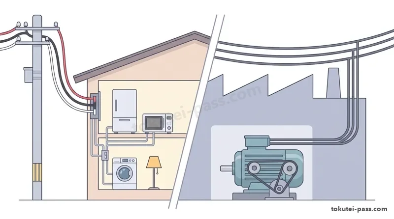
Key points
- リアクタンスxを含む三相3線式の線間電圧降下は「ΔV=√3×I×(r×cosθ+x×sinθ)(V)」で求める。
Line-to-line voltage drop in a three-phase 3-wire line including reactance x is "ΔV = √3 × I × (r × cosθ + x × sinθ) (V)". - 力率cosθ=0.8のときsinθ=0.6、力率cosθ=0.6のときsinθ=0.8(3:4:5の関係)を使って素早く計算する。
Use the 3 : 4 : 5 right-triangle ratio for fast mental math: when cosθ = 0.8, sinθ = 0.6; when cosθ = 0.6, sinθ = 0.8. - 途中分岐がある配電線路では、電源側の区間に全負荷電流の和が流れるとして区間別に電圧降下を合計する。
On a distribution line with intermediate taps, the upstream section carries the sum of all downstream load currents; sum the voltage drops of each section. - 【例】三相3線式高圧線路で1線の抵抗 r = 0.6Ω、リアクタンス x = 0.8Ω、線電流 I = 50A、力率 cosθ = 0.8(sinθ = 0.6)のとき → 電圧降下 ΔV = 1.73 × 50 ×(0.6 × 0.8 + 0.8 × 0.6)= 86.5 × 0.96 ≈ 83V
Example: In a 3-phase 3-wire HV line with resistance r = 0.6Ω and reactance x = 0.8Ω per wire, line current I = 50A, and cosθ = 0.8 (sinθ = 0.6) → Voltage drop ΔV = 1.73 × 50 × (0.6 × 0.8 + 0.8 × 0.6) = 86.5 × 0.96 ≈ 83V
| Word | Meaning |
|---|---|
| 電圧降下(ΔV) | voltage drop (ΔV) |
| 線路リアクタンス(x) | line reactance (x) |
| 無効率(sinθ) | reactive factor (sinθ) |
| 三相4線式配電方式 | three-phase 4-wire distribution system |
単相3線式の異力率の中性線電流・中性線断線と線路電力損失
Neutral Current with Different Power Factors, Neutral Disconnection in 1P3W and Line Power Loss
単相3線式回路(210V/105Vなど)において、上段の負荷Aと下段の負荷Bの力率が異なる場合(例:上段が力率cosθ=0.5のコイル負荷、下段が力率1.0の抵抗負荷)、中性線電流INは単純な引き算(IA−IB)にはなりません。
In a single-phase 3-wire circuit (such as 210V/105V), when the upper load A and lower load B have different power factors (e.g., an inductive load with cosθ = 0.5 on the upper side and a resistive load with cosθ = 1.0 on the lower side), the neutral wire current IN is not a simple subtraction (IA − IB).
上段電流IAと下段電流IBが同じ大きさIで、位相差が60度(cos60°=0.5)ある場合、ベクトル図の正三角形の関係から、中性線に流れる差のベクトル電流INは元の電流Iと全く同じ大きさ(IN=I)になります。
When upper current IA and lower current IB have the same magnitude I and a phase difference of 60 degrees (cos60° = 0.5), the vector diagram forms an equilateral triangle, so the difference vector current IN flowing in the neutral wire has the exact same magnitude I as the outer currents (IN = I).
また単相3線式回路で中性線が断線すると、上下の105V負荷RAとRBが外線間の210Vに直列接続された状態になります。すると抵抗値が大きい(消費電力が小さい)方の負荷に210Vの大半が分圧され、過電圧による焼損事故が起きます。
Furthermore, if the neutral wire breaks in a single-phase 3-wire circuit, the upper and lower 105V loads RA and RB become connected in series across the 210V outer lines. Most of the 210V then divides across whichever load has the larger resistance (smaller wattage), causing burnout from overvoltage.
問7で頻出の配電線路の電力損失Pl(W)では、負荷電力P(W)と力率cosθからまず線電流Iを逆算します。三相3線式では「I=P÷(√3×V×cosθ)」を3線分の損失式「Pl=3×I²×r」に代入し、「Pl=(P²×r)÷(V²×cos²θ)」となります。
For distribution line power loss Pl (W), which appears frequently in Question 7, first calculate line current I from load power P (W) and power factor cosθ. In a three-phase 3-wire line, substituting "I = P ÷ (√3 × V × cosθ)" into the 3-wire loss formula "Pl = 3 × I² × r" gives "Pl = (P² × r) ÷ (V² × cos²θ)".
Key points
- 単相3線式で上段が力率0.5(遅れ)・下段が力率1.0で電流の大きさがともにIのとき、位相差60°のため中性線電流INも「I」になる。
In a 1-phase 3-wire circuit where the upper load has cosθ = 0.5 (lagging), the lower load has cosθ = 1.0, and both carry current I, the 60° phase difference makes the neutral current IN equal to "I". - 単相3線式の中性線が断線すると、上下の負荷に210Vが抵抗比で分圧され、抵抗が大きい機器に異常過電圧がかかる。
If the neutral wire of a 1-phase 3-wire line breaks, 210V divides across the upper and lower loads in proportion to resistance, applying dangerous overvoltage to the higher-resistance appliance. - 力率cosθの負荷への送電損失Plは、電流「I=P÷(V×cosθ)」が力率に反比例するため、「cos²θ」に反比例する。
Transmission line loss Pl for a load of power factor cosθ is inversely proportional to "cos²θ" because current "I = P ÷ (V × cosθ)" is inversely proportional to cosθ. - 【例】単相3線式(100V/200V、1線抵抗 r = 0.2Ω)で上段・下段ともに 100V・1.6kW・力率 0.8 の同種負荷のとき → 線電流 I = 1,600 ÷(100 × 0.8)= 20A、中性線電流は 0A、全線路損失 Pl = 2 × 20² × 0.2 = 160W
Example: In a 1-phase 3-wire line (100V/200V, resistance r = 0.2Ω per wire) where both upper and lower loads are identical 100V, 1.6kW, cosθ = 0.8 loads → Line current I = 1,600 ÷ (100 × 0.8) = 20A, neutral current is 0 A, total line loss Pl = 2 × 20² × 0.2 = 160W
| Word | Meaning |
|---|---|
| 中性線電流(IN) | neutral wire current (IN) |
| 中性線断線による過電圧 | overvoltage due to neutral disconnection |
| 線路電力損失(Pl) | line power loss (Pl) |
| ベクトル合成 | vector composition |
高圧進相コンデンサ(SC)と直列リアクトル(SR)および力率改善
High-Voltage Power Capacitors (SC), Series Reactors (SR) and Power Factor Improvement
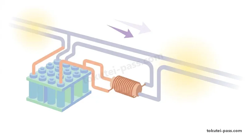
工場やビルの誘導電動機などは遅れ力率で運転されるため、受電設備に「高圧進相コンデンサ(SC)」を並列接続して進み無効電力を供給し、全体の力率cosθを1(100%)に近づけます。
Because induction motors in factories and buildings operate at a lagging power factor, "high-voltage power capacitors (SC)" are connected in parallel at the receiving facility to supply leading reactive power and bring the overall power factor cosθ closer to 1 (100%).
1相あたりの静電容量C(F)のコンデンサ3個を「Y結線」にして線間電圧V(V)・周波数f(Hz)の三相電源につないだとき、相電圧はV÷√3なので、充電電流は「I=(2πfCV)÷√3(A)」、三相無効電力(容量)は「Q=√3×V×I=2πfCV²(var)」となります(Δ結線ならIもQも3倍になります)。
When three capacitors of capacitance C (F) per phase are connected in "star (Y)" across a three-phase source of line voltage V (V) and frequency f (Hz), since phase voltage is V ÷ √3, the charging current is "I = (2πfCV) ÷ √3 (A)" and the three-phase reactive power (capacity) is "Q = √3 × V × I = 2πfCV² (var)" (in Δ connection, both I and Q are 3 times larger).
またY結線のコンデンサ(容量性リアクタンスXC)に高調波対策用の「直列リアクトル(SR:誘導性リアクタンスXL)」を直列接続した場合、1相の合成リアクタンスは「XC−XL」に減るため、設備の三相容量Qは「Q=V²÷(XC−XL)(var)」となります。
When a "series reactor (SR: inductive reactance XL)" for harmonic suppression is connected in series with Y-connected capacitors (capacitive reactance XC), the net reactance per phase decreases to "XC − XL", so the three-phase capacity Q of the bank becomes "Q = V² ÷ (XC − XL) (var)".
さらに、消費電力P(kW)の負荷に力率1.0の抵抗負荷やコンデンサを追加したときの合成皮相電力S(kVA)を求める問題では、有効電力の合計「ΣP(kW)」と無効電力の合計「ΣQ(kvar)」を別々に計算し、三平方の定理「S=√((ΣP)²+(ΣQ)²)(kVA)」で合成します。
Moreover, to find the combined apparent power S (kVA) when a resistive load (cosθ = 1.0) or capacitor is added to an existing load P (kW), sum the active powers "ΣP (kW)" and reactive powers "ΣQ (kvar)" separately, then combine them using the Pythagorean theorem: "S = √((ΣP)² + (ΣQ)²) (kVA)".
Key points
- Y結線の三相コンデンサ(1相容量C)の電流は「I=2πfCV÷√3(A)」、三相容量は「Q=2πfCV²(var)」。
For Y-connected three-phase capacitors (capacitance C per phase), current is "I = 2πfCV ÷ √3 (A)" and three-phase capacity is "Q = 2πfCV² (var)". - Y結線のコンデンサXCに直列リアクトルXLをつないだときの三相容量は「Q=V²÷(XC−XL)(var)」。
When a series reactor XL is connected to Y-connected capacitors XC, the three-phase capacity is "Q = V² ÷ (XC − XL) (var)". - 複数の負荷を合わせた合成皮相電力S(kVA)は、有効電力の和ΣPと無効電力の和ΣQから「S=√((ΣP)²+(ΣQ)²)」で求める。
Combined apparent power S (kVA) of multiple loads is found from total active power ΣP and total reactive power ΣQ via "S = √((ΣP)² + (ΣQ)²)". - 【例】有効電力 90kW・遅れ無効電力 120kvar の負荷に、力率 1.0 の電熱器 70kW を追加したとき → 合計有効電力 ΣP = 90 + 70 = 160kW、合計無効電力 ΣQ = 120kvar、合成皮相電力 S = √(160² + 120²)= 200kVA
Example: Adding a 70kW electric heater (cosθ = 1.0) to a load with 90kW active power and 120kvar lagging reactive power → Total active power ΣP = 90 + 70 = 160kW, total reactive power ΣQ = 120kvar, combined apparent power S = √(160² + 120²) = 200kVA
| Word | Meaning |
|---|---|
| 高圧進相コンデンサ(SC) | high-voltage power capacitor (SC) |
| 直列リアクトル(SR) | series reactor (SR) |
| 無効電力(kvar)と皮相電力(kVA) | reactive power (kvar) and apparent power (kVA) |
| 力率改善 | power factor improvement |
百分率インピーダンス(%Z)と三相短絡電流(Is)の計算
Percent Impedance (%Z) and Three-Phase Short-Circuit Current (Is) Calculations
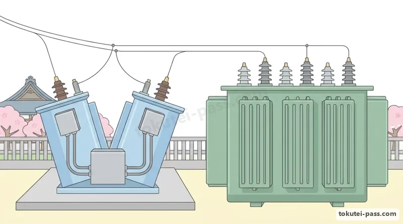
問8で毎回出題される最重要テーマが「百分率インピーダンス(パーセントインピーダンス:%Z)」と「三相短絡電流Is」です。高圧受電設備の遮断器(VCBなど)は、受電点で三相短絡事故が起きたときの大電流Isを安全に切れる遮断容量を持つ必要があります。
A crucial topic tested in Question 8 of every exam is "percent impedance (%Z)" and "three-phase short-circuit current Is." The circuit breaker (such as a VCB) in a high-voltage receiving facility must have sufficient breaking capacity to safely interrupt the massive current Is during a three-phase short circuit at the receiving point.
定格線間電圧Vn(V)、定格電流In(A)、定格容量(基準容量)Pn=√3VnIn(VA)、1相あたりのインピーダンスZ(Ω)のとき、相電圧Vn÷√3に対するインピーダンス電圧降下InZの割合を百分率で表したものが「%Z」です。
Given rated line voltage Vn (V), rated current In (A), rated capacity (base capacity) Pn = √3VnIn (VA), and impedance Z (Ω) per phase, "%Z" is the ratio of the impedance voltage drop InZ to the phase voltage Vn ÷ √3, expressed as a percentage.
式を整理すると「%Z=(√3×In×Z÷Vn)×100=(Pn×Z÷Vn²)×100(%)」となります。もし容量PA(kVA)基準の%ZAを、別の基準容量PB(例:10MVA=10,000kVA)に換算するときは、容量に比例させて「%ZB=%ZA×(PB÷PA)」で計算します。
Simplifying the expression gives "%Z = (√3 × In × Z ÷ Vn) × 100 = (Pn × Z ÷ Vn²) × 100 (%)". To convert a percent impedance %ZA based on capacity PA (kVA) to another base capacity PB (e.g., 10MVA = 10,000kVA), scale it proportionally to capacity: "%ZB = %ZA × (PB ÷ PA)".
受電点までの合成パーセントインピーダンス%Z(%)が分かれば、三相短絡電流Is(A)は定格電流Inの「100÷%Z倍」、すなわち「Is=(100÷%Z)×In(A)」で簡単に求まります。特に基準容量10MVA(10,000kVA)、線間電圧V(kV)のときは「Is=1,000÷(√3×V×Z)(kA)」となります。
Once the total percent impedance %Z (%) up to the receiving point is known, the three-phase short-circuit current Is (A) is simply "100 ÷ %Z times" the rated current In: "Is = (100 ÷ %Z) × In (A)". Specifically, for a standard base capacity of 10MVA (10,000kVA) and line voltage V (kV), "Is = 1,000 ÷ (√3 × V × Z) (kA)".
Key points
- 百分率インピーダンスの定義式は「%Z=(√3×In×Z÷Vn)×100=(Pn×Z÷Vn²)×100(%)」。
The definition formula for percent impedance is "%Z = (√3 × In × Z ÷ Vn) × 100 = (Pn × Z ÷ Vn²) × 100 (%)". - 基準容量をPAからPBに揃える換算式は、容量の比を掛ける「%ZB=%ZA×(PB÷PA)」。
To convert base capacity from PA to PB, multiply by the capacity ratio: "%ZB = %ZA × (PB ÷ PA)". - 三相短絡電流Isは「Is=(100÷%Z)×In(A)」で求め、遮断器の定格遮断電流はIsより大きいものを選択する。
Three-phase short-circuit current Is is "Is = (100 ÷ %Z) × In (A)", and the circuit breaker's rated breaking current must exceed Is. - 【例】基準容量 10MVA における電源側 %Z1 = 3.0%、容量 500kVA(0.5MVA)の変圧器の自己容量基準 %Z2 = 4.0% のとき → 10MVA基準に換算した変圧器の %Z2' = 4.0 ×(10 ÷ 0.5)= 80%、合計 %Z = 3.0 + 80 = 83%
Example: Grid side %Z1 = 3.0% on a 10MVA base, connected to a 500kVA (0.5MVA) transformer with self-base %Z2 = 4.0% → Transformer %Z2' converted to 10MVA base is 4.0 × (10 ÷ 0.5) = 80%, giving total %Z = 3.0 + 80 = 83%
| Word | Meaning |
|---|---|
| 百分率インピーダンス(%Z) | percent impedance (%Z) |
| 基準容量(10MVA) | base capacity (10MVA) |
| 三相短絡電流(Is) | three-phase short-circuit current (Is) |
| 遮断容量 | breaking capacity |
需要率・不等率・負荷率と変圧器のタップ電圧調整
Demand Factor, Diversity Factor, Load Factor and Transformer Tap Voltage Adjustment
受電設備の変圧器容量を経済的に設計するため、「需要率」「不等率」「負荷率」の3つの指標を使います。すべての負荷設備が同時に100%フル稼働することはまれだからです。
To economically design transformer capacity in a receiving facility, three indicators are used: "demand factor," "diversity factor," and "load factor," because all connected load equipment rarely operates at 100% full capacity simultaneously.
「需要率(%)」は、設備容量の合計に対する最大需要電力の割合であり、「最大需要電力=設備容量合計×需要率」となります。需要率は通常100%以下になります。
"Demand factor (%)" is the ratio of maximum demand power to the total installed equipment capacity: "Maximum demand power = Total installed capacity × Demand factor". The demand factor is normally 100% or less.
「不等率」は、各負荷群の最大需要電力のピーク時間がずれる度合いを表し、「不等率=各負荷の最大需要電力の和÷合成最大需要電力」で定義されます(必ず1.0以上になります)。また「負荷率(%)」は「平均需要電力÷最大需要電力×100」です。
"Diversity factor (不等率)" represents how much the peak demand times of different load groups are staggered, defined as "Diversity factor = Sum of individual maximum demands ÷ Combined maximum demand" (always 1.0 or greater). "Load factor (%)" is "Average demand power ÷ Maximum demand power × 100".
一方、高圧受電用変圧器には一次側巻線に「タップ(巻数調整端子:6,750V・6,600V・6,450V・6,300Vなど)」が付いています。二次側電圧V2は一次タップ電圧Vtに反比例するため、一次タップを6,600Vから6,300Vへ下げると、二次電圧は「6,600÷6,300倍」に上昇します。
Meanwhile, a high-voltage receiving transformer has "taps (turns-adjustment terminals such as 6,750V, 6,600V, 6,450V, 6,300V)" on its primary winding. Because secondary voltage V2 is inversely proportional to primary tap voltage Vt, lowering the primary tap from 6,600V to 6,300V raises the secondary voltage by "6,600 ÷ 6,300 times".
Key points
- 合成最大需要電力は「(設備容量×需要率)の合計÷不等率」で求める(不等率は必ず1以上)。
Combined maximum demand power is found by "Sum of (Installed capacity × Demand factor) ÷ Diversity factor" (diversity factor is always ≥ 1). - 負荷率(%)は「平均需要電力÷最大需要電力×100」であり、設備がどれだけ平坦に使われているかを示す。
Load factor (%) is "Average demand power ÷ Maximum demand power × 100", indicating how evenly the facility is utilized. - 変圧器の一次タップ電圧をVt1からVt2に変えると、二次電圧V2は逆比の「V2'=V2×(Vt1÷Vt2)」に変わる。
Changing the primary tap voltage of a transformer from Vt1 to Vt2 changes the secondary voltage V2 in inverse proportion: "V2' = V2 × (Vt1 ÷ Vt2)". - 【例】一次 6,600Vタップのとき二次電圧が 200Vだった変圧器を、一次 6,300Vタップに切り替えたとき → 新しい二次電圧 V2' = 200 ×(6,600 ÷ 6,300)≈ 210V(約10V上昇する)
Example: A transformer giving 200V secondary voltage on the 6,600V primary tap is switched to the 6,300V primary tap → New secondary voltage V2' = 200 × (6,600 ÷ 6,300) ≈ 210V (rises by about 10V)
| Word | Meaning |
|---|---|
| 需要率と最大需要電力 | demand factor and maximum demand power |
| 不等率(1.0以上) | diversity factor (1.0 or greater) |
| 負荷率と平均需要電力 | load factor and average demand power |
| 変圧器のタップ電圧 | transformer tap voltage |
支線の水平張力計算・低圧分岐回路設計と完全地絡時の対地電圧
Guy Wire Horizontal Tension, LV Branch Circuit Design and Voltage to Ground Under Bolted Ground Fault
問9では、電柱を支える「支線の張力」、低圧幹線からの「分岐回路の電線太さと長さ」、または低圧側で完全地絡が起きたときの「外箱の対地電圧」が出題されます。
Question 9 tests the calculation of "guy wire tension" supporting a utility pole, "branch wire size and length" tapped from a low-voltage feeder, or "enclosure voltage to ground" during a complete ground fault on the low-voltage side.
電柱と角度θ(シータ:よく30°が出る)をなして張られた支線(引張強さTS、安全率K)が支えることができる水平方向の最大張力Tは、許容張力「TS÷K」に「sinθ」を掛けた「T=(TS÷K)×sinθ」で求めます(sin30°=0.5)。
When a guy wire (tensile strength TS, safety factor K) is installed at an angle θ (often 30°) to a utility pole, the maximum horizontal tension T it can support is the allowable tension "TS ÷ K" multiplied by "sinθ": "T = (TS ÷ K) × sinθ" (where sin30° = 0.5).
また定格電流IBの過電流遮断器で保護された低圧幹線から分岐する場合、原則は分岐点から3m以下に遮断器を設けますが、分岐電線の許容電流Iwが「IBの35%以上なら8m以下まで」、「IBの55%以上なら長さ制限なし」で施設できます。
When tapping a branch circuit from a low-voltage feeder protected by an overcurrent breaker rated at IB, a breaker must normally be installed within 3m of the tap point; however, if the branch wire allowable current Iw is "at least 35% of IB, it can extend up to 8m", and if "at least 55% of IB, there is no length limit".
さらに、変圧器二次側(線間電圧V=210Vなど)の片線にB種接地抵抗RB、負荷機器の金属製外箱にD種接地抵抗RDが施されている回路で、非接地側電線が外箱に完全地絡したとき、外箱の対地電圧VAはRDへの分圧「VA=V×RD÷(RB+RD)(V)」となります。
Furthermore, in a transformer secondary circuit (line voltage V = 210V, etc.) where one wire has Class B grounding resistance RB and a load enclosure has Class D grounding resistance RD, if the ungrounded wire suffers a complete ground fault to the enclosure, the enclosure voltage to ground VA is found by voltage division across RD: "VA = V × RD ÷ (RB + RD) (V)".
Key points
- 電柱と角度θをなす支線が耐えられる最大水平張力Tは「T=(引張強さTS÷安全率K)×sinθ」(sin30°=0.5)。
Maximum horizontal tension T supported by a guy wire at angle θ to a pole is "T = (Tensile strength TS ÷ Safety factor K) × sinθ" (sin30° = 0.5). - 幹線遮断器IBからの分岐距離:原則3m以下、許容電流「Iw≧0.35×IBなら8m以下」、「Iw≧0.55×IBなら制限なし」。
Tap distance from feeder breaker IB: normally ≤ 3m; if branch allowable current "Iw ≥ 0.35 × IB then ≤ 8m", if "Iw ≥ 0.55 × IB then unlimited". - 二次側V(V)の回路で外箱(接地抵抗RD)に完全地絡したときの外箱対地電圧は「VA=V×RD÷(RB+RD)(V)」。
During a complete ground fault to an enclosure (ground resistance RD) in a secondary circuit of V (V), enclosure voltage to ground is "VA = V × RD ÷ (RB + RD) (V)". - 【例】二次電圧 V = 210V、B種接地抵抗 RB = 10Ω、D種接地抵抗 RD = 40Ωの機器外箱に完全地絡したとき → 外箱の対地電圧 VA = 210 × 40 ÷(10 + 40)= 168V(RBを分子にして42Vとしないよう注意!)
Example: With secondary voltage V = 210V, Class B ground resistance RB = 10Ω, and Class D ground resistance RD = 40Ω on an enclosure during a complete ground fault → Enclosure voltage to ground VA = 210 × 40 ÷ (10 + 40) = 168V (do not put RB in the numerator to get 42V!)
| Word | Meaning |
|---|---|
| 支線の水平張力と安全率 | horizontal tension of guy wire and safety factor |
| 幹線分岐の3m・8mルール | 3m and 8m feeder tap rules |
| 完全地絡と対地電圧 | complete ground fault and voltage to ground |
| 許容電流(Iw) | allowable current (Iw) |
試験によく出るポイントと覚え方
Key Exam Points & How to Remember
問6の単相3線式回路で「上段の力率cosθ=0.5、下段の力率cosθ=1.0、上下の電流がともにI(A)」という問題が出たら、計算するまでもなく中性線電流INは「I(A)そのもの(例:ともに20Aなら中性線も20A)」になります(60度の正三角形になるため)。
In Question 6 on single-phase 3-wire circuits, if a problem states "upper load power factor cosθ = 0.5, lower load power factor cosθ = 1.0, and both upper and lower currents have the same magnitude I (A)", no calculation is needed: the neutral wire current IN is "equal to I (A) itself" (e.g., if both are 20A, neutral current is also 20A because the vectors form a 60° equilateral triangle).
問7の線路電力損失の文字式では、三相3線式の1線電流「I=P÷(√3Vcosφ)」を「Pl=3I²r」に代入すると、分子の3と分母の(√3)²=3がきれいに約分されて消え、「Pl=P²r÷(V²cos²φ)」と係数のないシンプルで美しい式が残ります。
In Question 7 symbolic formulas for line power loss in a three-phase 3-wire line, substituting line current "I = P ÷ (√3Vcosφ)" into "Pl = 3I²r" neatly cancels the 3 in the numerator with (√3)² = 3 in the denominator, leaving the clean coefficient-free formula "Pl = P²r ÷ (V²cos²φ)".
問8の三相短絡電流「Is=(100÷%Z)×In」と、問9の高圧進相コンデンサ容量「Q=2πfCV²(Y結線)」および直列リアクトル付き容量「Q=V²÷(XC−XL)」は、過去問で何度も同じ式が出題されているため丸暗記しておきましょう。
In Questions 8 and 9, the formulas for three-phase short-circuit current "Is = (100 ÷ %Z) × In", Y-connected high-voltage capacitor capacity "Q = 2πfCV²", and capacity with a series reactor "Q = V² ÷ (XC − XL)" appear repeatedly in past exams—memorize them verbatim.
Key points
- 三相3線式の電圧降下:「ΔV=√3×I×(r×cosθ+x×sinθ)」、三相電力損失:「Pl=3I²r=P²r÷(V²cos²φ)」。
3-phase 3-wire voltage drop: "ΔV = √3 × I × (r × cosθ + x × sinθ)"; 3-phase line power loss: "Pl = 3I²r = P²r ÷ (V²cos²φ)". - 百分率インピーダンスと短絡電流:「%Z=(Pn×Z÷Vn²)×100」、三相短絡電流「Is=(100÷%Z)×In」。
Percent impedance and short-circuit current: "%Z = (Pn × Z ÷ Vn²) × 100", 3-phase short-circuit current "Is = (100 ÷ %Z) × In". - Y結線の高圧コンデンサ:「I=2πfCV÷√3(A)」「Q=2πfCV²(var)」、SR付きなら「Q=V²÷(XC−XL)(var)」。
Y-connected HV capacitors: "I = 2πfCV ÷ √3 (A)" and "Q = 2πfCV² (var)"; with series reactor SR: "Q = V² ÷ (XC − XL) (var)". - 需要率・不等率・負荷率:最大需要=設備容量×需要率、合成最大=各最大の和÷不等率、平均需要=最大×負荷率。
Demand, diversity, and load factors: Max demand = Installed × Demand factor; Combined max = Sum of max demands ÷ Diversity factor; Average = Max × Load factor. - 完全地絡時の外箱対地電圧:「VA=V×RD÷(RB+RD)」(分子は必ず外箱側のD種接地抵抗RDになる)。
Enclosure voltage to ground during complete ground fault: "VA = V × RD ÷ (RB + RD)" (the numerator is always the enclosure's Class D resistance RD).
| Word | Meaning |
|---|---|
| 正三角形ベクトル(位相差60°) | equilateral triangle vectors (60° phase difference) |
| 三相送電損失式(P²r÷V²cos²φ) | 3-phase line loss formula (P²r ÷ V²cos²φ) |
| 基準容量換算 | base capacity conversion |
| 分圧による地絡電圧 | ground fault voltage via voltage division |
Power Distribution & Wiring Design
Practice this chapter in the appOfficial references
- 一般財団法人 電気技術者試験センター「第一種電気工事士学科試験 出題範囲・出題例(2. 配電理論及び配線設計)」 — https://www.shiken.or.jp/construction/first/department/
- 経済産業省「電気設備の技術基準の解釈(低圧幹線・分岐回路及び接地工事)」 — https://www.meti.go.jp/policy/safety_security/industrial_safety/sangyo/electric/