
Basic Electrical Theory & Three-Phase AC
電気に関する基礎理論・三相交流
Class 1 Electrician 第一種電気工事士 (written exam) · 第一種電気工事士(学科試験) · Written by Tokutei Pass based on the official study texts; not copied verbatim.
クーロンの法則と平行板コンデンサの電界・静電容量
Coulomb's Law and Electric Field & Capacitance of Parallel-Plate Capacitors
第一種電気工事士の学科試験では、問1に静電気または電磁気の計算問題が出題されます。第二種にはない重要分野ですが、公式の形を覚えれば確実に得点できます。
In the First-Class Electrician written exam, Question 1 is always a calculation problem on electrostatics or electromagnetism. Although this topic does not appear in the Second-Class exam, memorizing the basic formula shapes guarantees full marks.
空気中に置かれた2つの点電荷Q1(C)とQ2(C)の間に働く静電気力F(N)は、電荷の積「Q1×Q2」に比例し、距離r(m)の2乗「r²」に反比例します。これをクーロンの法則と呼びます。
The electrostatic force F (N) acting between two point charges Q1 (C) and Q2 (C) placed in air is directly proportional to the product of the charges "Q1 × Q2" and inversely proportional to the square of the distance r (m) between them, "r²". This is called Coulomb's Law.
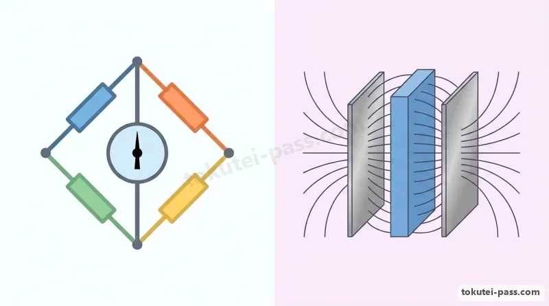
向かい合う2枚の金属板(極板)を距離d(m)だけ離して電圧V(V)を加えると、極板間には一様な電界が生じます。電界の強さE(V/m)は「E=V÷d」で求められ、距離dに反比例します。
When two facing metal plates (electrodes) are separated by a distance d (m) and a voltage V (V) is applied, a uniform electric field is created between the plates. The electric field strength E (V/m) is found by "E = V ÷ d" and is inversely proportional to the distance d.
平行板コンデンサの静電容量C(F)は、極板の面積S(m²)と絶縁物の誘電率ε(イプシロン)に比例し、極板間距離d(m)に反比例します(C=ε×S÷d)。面積が広く隙間が狭いほど電気を多く蓄えられます。
The capacitance C (F) of a parallel-plate capacitor is directly proportional to the plate area S (m²) and the permittivity ε (epsilon) of the insulator, and inversely proportional to the plate separation d (m) (C = ε × S ÷ d). Wider plates and a narrower gap allow more electric charge to be stored.
Key points
- クーロンの法則:静電気力Fは電荷の積「Q1×Q2」に比例し、距離の2乗「r²」に反比例する(距離が2倍なら力は1/4)。
Coulomb's Law: Electrostatic force F is proportional to the charge product "Q1 × Q2" and inversely proportional to distance squared "r²" (doubling distance reduces force to 1/4). - 平行板コンデンサの電界の強さE(V/m)は「E=V÷d」で計算する(dは必ずメートルmに換算する)。
Electric field strength E (V/m) of a parallel-plate capacitor is calculated by "E = V ÷ d" (always convert distance d into meters m). - 静電容量C(F)は「C=ε×S÷d」で表され、比誘電率εrの誘電体を入れると容量はεr倍になる。
Capacitance C (F) is given by "C = ε × S ÷ d"; inserting a dielectric with relative permittivity εr multiplies the capacitance by εr. - 【例】極板間距離 d = 4mm(0.004m)の平行板コンデンサに直流電圧 V = 200Vを加えたとき → 電界の強さ E = 200 ÷ 0.004 = 50,000V/m = 50kV/m
Example: Applying DC voltage V = 200V across a parallel-plate capacitor with plate separation d = 4mm (0.004m) → Electric field strength E = 200 ÷ 0.004 = 50,000V/m = 50kV/m
| Word | Meaning |
|---|---|
| クーロンの法則 | Coulomb's law |
| 電界の強さ(E=V÷d) | electric field strength (E = V ÷ d) |
| 静電容量(C) | capacitance (C) |
| 誘電率(ε) | permittivity (ε) |
コンデンサの直並列接続・分圧と静電エネルギー
Series-Parallel Capacitors, Voltage Division and Electrostatic Energy
静電容量C(F)のコンデンサに電圧V(V)を加えたときに蓄えられる電荷Q(C:クーロン)は「Q=C×V」であり、コンデンサ内部に蓄えられる静電エネルギーW(J:ジュール)は「W=0.5×C×V²=0.5×Q×V」となります。
When a voltage V (V) is applied to a capacitor of capacitance C (F), the stored electric charge Q (C: coulomb) is "Q = C × V", and the electrostatic energy W (J: joule) stored inside the capacitor is "W = 0.5 × C × V² = 0.5 × Q × V".
試験で特に注意すべきなのは単位の換算です。静電容量は「μF(マイクロファラド=10⁻⁶F)」で与えられることが多いため、電圧Vが何百ボルトから何千ボルトのときに10⁻⁶を掛けてジュール(J)に直します。
Unit conversion requires special care on the exam. Because capacitance is usually given in "μF (microfarads = 10⁻⁶F)", when the voltage V is several hundred to several thousand volts, you must multiply by 10⁻⁶ to convert the result into joules (J).
複数のコンデンサをつなぐ場合、合成静電容量Cの計算式は抵抗のときと正反対になります。並列接続では極板面積が増えるため単純な和「C=C1+C2」になり、直列接続では和分の積「C=(C1×C2)÷(C1+C2)」になります。
When connecting multiple capacitors, the formulas for combined capacitance C are the exact opposite of those for resistors. Parallel connection increases the effective plate area and gives a simple sum "C = C1 + C2", whereas series connection follows product over sum "C = (C1 × C2) ÷ (C1 + C2)".
2つのコンデンサC1とC2を直列接続して電源電圧Vを加えると、両方のコンデンサには全く同じ電荷Qが蓄えられます。そのため、各コンデンサにかかる電圧は静電容量の逆比に分圧され、容量が小さい方に高い電圧がかかります。
When two capacitors C1 and C2 are connected in series across a source voltage V, both capacitors store the exact same charge Q. Consequently, the voltage across each capacitor divides in inverse proportion to its capacitance, meaning the smaller capacitor bears the higher voltage.
Key points
- 蓄えられる電荷は「Q=C×V(C)」、静電エネルギーは「W=0.5×C×V²(J)」で求める(1μF=10⁻⁶F)。
Stored charge is "Q = C × V (C)" and electrostatic energy is "W = 0.5 × C × V² (J)" (remember 1μF = 10⁻⁶F). - 合成静電容量は抵抗と逆で、並列接続が足し算「C1+C2」、2個の直列接続が「(C1×C2)÷(C1+C2)」。
Combined capacitance is opposite to resistance: parallel connection adds as "C1 + C2", and two in series use "(C1 × C2) ÷ (C1 + C2)". - 直列接続では電荷Qが等しくなり、電圧は容量の逆比に分圧される:「V1=V×C2÷(C1+C2)」。
In a series connection, charge Q is equal and voltage divides in inverse proportion to capacitance: "V1 = V × C2 ÷ (C1 + C2)". - 【例】静電容量 C = 20μF のコンデンサに直流電圧 V = 500V を充電したとき → 静電エネルギー W = 0.5 ×(20 × 10⁻⁶)× 500² = 2.5J
Example: Charging a capacitor of C = 20μF to a DC voltage of V = 500V → Electrostatic energy W = 0.5 × (20 × 10⁻⁶) × 500² = 2.5J
| Word | Meaning |
|---|---|
| 静電エネルギー(W=0.5CV²) | electrostatic energy (W = 0.5CV²) |
| 電荷(Q=CV) | electric charge (Q = CV) |
| 合成静電容量 | combined capacitance |
| 容量の逆比による分圧 | inverse-capacitance voltage division |
電磁誘導・自己インダクタンスと鉄心入りコイルの特性
Electromagnetic Induction, Self-Inductance and Iron-Core Coil Characteristics
コイルを貫く磁束Φ(ウェーバ:Wb)が時間とともに変化すると、その変化を妨げる向き(レンツの法則)に誘導起電力e(V)が生じます。これをファラデーの電磁誘導の法則といい、変圧器や発電機の原理となります。
When the magnetic flux φ (weber: Wb) passing through a coil changes over time, an induced electromotive force e (V) is generated in a direction that opposes the change (Lenz's Law). This is Faraday's Law of Electromagnetic Induction, the operating principle of transformers and generators.
自分自身のコイルに流れる電流I(A)が変化したときに生じる起電力の大きさは、自己インダクタンスL(ヘンリー:H)を用いて「e=L×(ΔI÷Δt)」と表されます。またコイルが蓄える電磁エネルギーは「W=0.5×L×I²(J)」です。
The magnitude of the electromotive force induced when the current I (A) in the coil itself changes is expressed using self-inductance L (henry: H) as "e = L × (ΔI ÷ Δt)". The electromagnetic energy stored in the coil is "W = 0.5 × L × I² (J)".
コイルの自己インダクタンスLは、鉄心の透磁率μ(ミュー)と断面積Sに比例し、磁路の長さlに反比例し、さらにコイルの「巻数Nの2乗(N²)」に比例します。巻数を2倍にするとインダクタンスLは4倍になります。
The self-inductance L of a coil is directly proportional to the magnetic permeability μ (mu) and cross-sectional area S of the iron core, inversely proportional to the magnetic path length l, and proportional to the "square of the number of turns N (N²)". Doubling the turns N quadruples the inductance L.
したがって、鉄心入りコイルに交流電圧V(周波数f)を加えたとき、誘導性リアクタンス「XL=2πfL」によって電流「I=V÷XL」が制限制御されます。運転中に鉄心を引き抜くと透磁率μが激減してLとXLが小さくなり、過大な電流Iが流れます。
Therefore, when AC voltage V (frequency f) is applied to an iron-core coil, the current "I = V ÷ XL" is limited by the inductive reactance "XL = 2πfL". Pulling out the iron core while energized drastically reduces permeability μ, lowering L and XL and causing an excessive current I to flow.
Key points
- 自己誘導起電力は「e=L×(ΔI÷Δt)(V)」、コイルに蓄えられる電磁エネルギーは「W=0.5×L×I²(J)」。
Self-induced EMF is "e = L × (ΔI ÷ Δt) (V)", and electromagnetic energy stored in a coil is "W = 0.5 × L × I² (J)". - コイルの自己インダクタンスL(H)は、透磁率μと巻数の2乗「N²」に比例する。
Self-inductance L (H) of a coil is proportional to permeability μ and the square of the number of turns "N²". - 交流電源につないだコイルから鉄心を抜くと、インダクタンスLが減って電流Iが大きく増加する。
Removing the iron core from an AC-energized coil decreases inductance L and causes the current I to increase sharply. - 【例】自己インダクタンス L = 0.4H のコイルに電流 I = 5A が流れているとき → 蓄えられる電磁エネルギー W = 0.5 × 0.4 × 5² = 5J
Example: When a current I = 5A flows through a coil with self-inductance L = 0.4H → Stored electromagnetic energy W = 0.5 × 0.4 × 5² = 5J
| Word | Meaning |
|---|---|
| 電磁誘導の法則 | law of electromagnetic induction |
| 自己インダクタンス(L) | self-inductance (L) |
| 透磁率(μ) | magnetic permeability (μ) |
| 電磁エネルギー(W=0.5LI²) | electromagnetic energy (W = 0.5LI²) |
キルヒホッフの法則(2電源回路)とホイートストンブリッジ回路
Kirchhoff's Laws (Two-Source Circuits) and Wheatstone Bridge Circuits
問2では直流回路の計算が必ず1問出題されます。第一種では単なる直並列合成だけでなく、2つの直流電源を持つ回路や、ブリッジ回路の2点間の電位差(電圧Vab)を求める問題が頻出です。
Question 2 always features one DC circuit calculation problem. The First-Class exam frequently tests not only series-parallel combinations, but also DC circuits with two voltage sources and finding the potential difference (voltage Vab) between two nodes of a bridge circuit.
キルヒホッフの第1法則(電流則)は「接続点に流れ込む電流の和と流れ出る電流の和は等しい」、第2法則(電圧則)は「任意の閉回路(ループ)において起電力の和と電圧降下(I×R)の和は等しい」という法則です。
Kirchhoff's First Law (Current Law) states that "the sum of currents entering a junction equals the sum of currents leaving it," and the Second Law (Voltage Law) states that "around any closed loop, the algebraic sum of electromotive forces equals the sum of voltage drops (I × R)."
また4つの抵抗R1・R2・R3・R4をひし形に組んだホイートストンブリッジ回路では、向かい合う対辺の抵抗の積が等しい「R1×R4=R2×R3」のときに平衡状態となり、中央の検流計(または電流計)に流れる電流は0Aになります。
In a Wheatstone bridge circuit with four resistors R1, R2, R3, and R4 arranged in a diamond, when the products of opposite resistor arms are equal ("R1 × R4 = R2 × R3"), the bridge is balanced and the current through the center galvanometer (or ammeter) is 0 A.
平衡していないブリッジ回路で中央の2点a−b間の電位差Vabを求める問題では、基準点(0V)を決めて各枝の分圧比から点aの電位Vaと点bの電位Vbを別々に計算し、その差「Vab=|Va−Vb|」をとると一瞬で解けます。
To find the potential difference Vab between two center nodes a–b in an unbalanced bridge circuit, choose a reference node (0 V), calculate the potentials Va and Vb of each branch separately using voltage division, and take their difference "Vab = |Va − Vb|" for an instant solution.
Key points
- キルヒホッフ第1法則は「接続点の流入電流=流出電流」、第2法則は「閉回路の起電力の和=電圧降下の和」。
Kirchhoff's 1st Law: "Inflow current = outflow current at a node"; 2nd Law: "Sum of EMFs = sum of voltage drops around a closed loop". - ホイートストンブリッジの平衡条件は対辺の積「R1×R4=R2×R3」であり、このとき中央の枝の電流は0Aになる。
The Wheatstone bridge balance condition is equal products of opposite arms "R1 × R4 = R2 × R3", making the center branch current 0 A. - 2点a−b間の電圧Vabは、各直列枝の分圧計算で電位Vaと電位Vbを求めて引き算する。
Voltage Vab between two nodes a–b is found by calculating potentials Va and Vb via voltage division on each series branch and subtracting. - 【例】電源 100V に対し、左枝が 20Ωと 30Ωの直列、右枝が 25Ωと 25Ωの直列のとき → 中間点の電位は Va = 100 × 30 ÷ 50 = 60V、Vb = 100 × 25 ÷ 50 = 50V となり、電位差 Vab = 60 − 50 = 10V
Example: With a 100V source where the left branch has 20Ω and 30Ω in series and the right branch has 25Ω and 25Ω in series → Midpoint potentials are Va = 100 × 30 ÷ 50 = 60V and Vb = 100 × 25 ÷ 50 = 50V, so Vab = 60 − 50 = 10V
| Word | Meaning |
|---|---|
| キルヒホッフの法則 | Kirchhoff's laws |
| ホイートストンブリッジ回路 | Wheatstone bridge circuit |
| 平衡条件(R1×R4=R2×R3) | balance condition (R1 × R4 = R2 × R3) |
| 電位差(Vab) | potential difference (Vab) |
正弦波交流(周期・周波数・角周波数)と周波数変化時のリアクタンス
Sinusoidal AC (Period, Frequency, Angular Frequency) and Reactance Under Frequency Change
問3では単相交流回路が出題されます。正弦波交流が1回の波を描くのにかかる時間を「周期T(s:秒)」、1秒間に繰り返す波の数を「周波数f(Hz:ヘルツ)」といい、「f=1÷T」の関係があります。
Question 3 covers single-phase AC circuits. The time required for a sinusoidal AC wave to complete one full cycle is the "period T (s: seconds)", and the number of cycles repeated per second is the "frequency f (Hz: hertz)", related by "f = 1 ÷ T".
また1秒間に進む角度(ラジアン)を「角周波数ω(オメガ:rad/s)」といい、「ω=2πf=2π÷T(π≈3.14)」で求めます。周波数f=50Hz(周期T=20ms=0.02s)のとき、角周波数は「ω=2×3.14×50=314rad/s」となります。
The angle in radians advanced per second is called the "angular frequency ω (omega: rad/s)", calculated as "ω = 2πf = 2π ÷ T (π ≈ 3.14)". At frequency f = 50Hz (period T = 20ms = 0.02s), the angular frequency is "ω = 2 × 3.14 × 50 = 314 rad/s".
正弦波交流の最大値Vmは実効値Vの√2倍(Vm=√2×V≈1.41×V)、平均値Vavは最大値の2÷π倍です。日常の100Vや200Vという表示はすべて「実効値」を表しています。
The peak value Vm of a sine wave is √2 times the RMS value V (Vm = √2 × V ≈ 1.41 × V), and the average value Vav is 2 ÷ π times the peak value. Standard ratings such as 100V or 200V always represent the "RMS (effective) value".
コイルの誘導性リアクタンス「XL=ωL=2πfL(Ω)」は周波数fに比例し、コンデンサの容量性リアクタンス「XC=1÷(ωC)=1÷(2πfC)(Ω)」は周波数fに反比例します。電源周波数が50Hzから60Hz(1.2倍)に変わると、XLは1.2倍に増え、XCは1÷1.2倍に減ります。
Inductive reactance of a coil "XL = ωL = 2πfL (Ω)" is proportional to frequency f, while capacitive reactance of a capacitor "XC = 1 ÷ (ωC) = 1 ÷ (2πfC) (Ω)" is inversely proportional to frequency f. When power frequency changes from 50Hz to 60Hz (1.2 times), XL increases by 1.2 times and XC decreases to 1 ÷ 1.2 times.
Key points
- 周波数は「f=1÷T(Hz)」、角周波数は「ω=2πf(rad/s)」であり、f=50Hz(T=20ms)なら「ω≈314rad/s」。
Frequency is "f = 1 ÷ T (Hz)" and angular frequency is "ω = 2πf (rad/s)"; for f = 50Hz (T = 20ms), "ω ≈ 314 rad/s". - 正弦波交流の最大値は実効値の√2倍:「Vm=√2×V」。
The peak value of sinusoidal AC is √2 times the RMS value: "Vm = √2 × V". - コイルの「XL=2πfL」は周波数fに比例し、コンデンサの「XC=1÷(2πfC)」は周波数fに反比例する。
Coil reactance "XL = 2πfL" is proportional to frequency f, whereas capacitor reactance "XC = 1 ÷ (2πfC)" is inversely proportional to f. - 【例】50Hzのとき XL = 10Ω、XC = 12Ωの直列回路を 60Hz(1.2倍)の電源につないだとき → 新しい XL' = 10 × 1.2 = 12Ω、XC' = 12 ÷ 1.2 = 10Ω となり、合成リアクタンス X = 12 − 10 = 2Ω
Example: A series circuit with XL = 10Ω and XC = 12Ω at 50Hz is connected to a 60Hz (1.2×) source → New XL' = 10 × 1.2 = 12Ω and XC' = 12 ÷ 1.2 = 10Ω, giving net reactance X = 12 − 10 = 2Ω
| Word | Meaning |
|---|---|
| 周期(T)と周波数(f) | period (T) and frequency (f) |
| 角周波数(ω=2πf) | angular frequency (ω = 2πf) |
| 誘導性リアクタンス(XL) | inductive reactance (XL) |
| 容量性リアクタンス(XC) | capacitive reactance (XC) |
単相交流R-L-C直並列回路・共振と半波整流回路
Single-Phase R-L-C Series/Parallel Circuits, Resonance and Half-Wave Rectifier Circuits
抵抗RとリアクタンスXL・XCが直列につながった回路の合成インピーダンスZ(Ω)は「Z=√(R²+(XL−XC)²)」で求め、力率cosθは「cosθ=R÷Z」となります。XL=XCのときは直列共振となり、リアクタンスが打ち消し合って「Z=R、力率cosθ=1(100%)」になります。
In a circuit with resistance R and reactances XL, XC in series, total impedance Z (Ω) is "Z = √(R² + (XL − XC)²)" and power factor cosθ is "cosθ = R ÷ Z". When XL = XC, series resonance occurs: the reactances cancel out, yielding "Z = R and power factor cosθ = 1 (100%)".
一方、抵抗Rの枝とリアクタンスXの枝が並列につながった回路では、各枝に同じ電源電圧Vがかかります。抵抗の電流「IR=V÷R」とリアクタンスの電流「IX=V÷X」は位相が90度ずれるため、全電流は「I=√(IR²+IX²)」、力率は「cosθ=IR÷I」で求めます。
Conversely, in a parallel circuit with a resistance branch R and a reactance branch X, the same source voltage V is applied to each branch. Because resistor current "IR = V ÷ R" and reactance current "IX = V ÷ X" are 90 degrees out of phase, total current is "I = √(IR² + IX²)" and power factor is "cosθ = IR ÷ I".
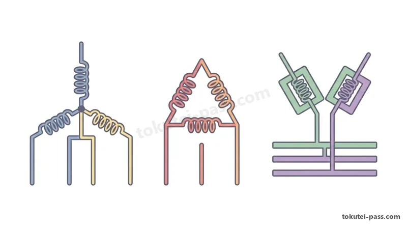
また問4で頻出なのが、交流電源(実効値V)に理想的な「半導体ダイオード」1個と抵抗Rを直列につないだ「半波整流回路」の消費電力Pを求める問題です。
A frequent Question 4 topic is finding the power consumption P of a "half-wave rectifier circuit" consisting of an AC source (RMS voltage V), a single ideal "semiconductor diode", and a resistor R connected in series.
ダイオードは一方向(順方向)にしか電流を通さないため、交流の1周期のうち正の半周期だけ電流が流れ、負の半周期は電流が0Aになります。したがって、抵抗Rで消費される平均電力Pはダイオードがないときの「半分(1/2)」、すなわち「P=V²÷(2×R)(W)」になります。
Because a diode conducts current in only one direction (forward bias), current flows only during the positive half-cycle of each AC period and is 0 A during the negative half-cycle. Consequently, the average power P consumed by resistor R is "exactly half (1/2)" that without a diode: "P = V² ÷ (2 × R) (W)".
Key points
- R-X並列回路では電流の直角三角形を作り、全電流「I=√(IR²+IX²)」、力率「cosθ=IR÷I」で計算する。
In an R-X parallel circuit, form a right triangle of branch currents to find total current "I = √(IR² + IX²)" and power factor "cosθ = IR ÷ I". - XL=XCとなる共振状態では、無効電流またはリアクタンス電圧が打ち消し合い、回路全体の力率cosθは1(100%)になる。
At resonance where XL = XC, reactive currents or voltages cancel out, making the overall circuit power factor cosθ = 1 (100%). - ダイオード1個の半波整流回路では正の半周期しか電流が流れないため、抵抗Rの消費電力は半分の「P=V²÷(2×R)(W)」になる。
In a single-diode half-wave rectifier circuit, current flows for only half a cycle, so power consumed in resistor R is halved: "P = V² ÷ (2 × R) (W)". - 【例】実効値 V = 100V の正弦波交流電源にダイオードと抵抗 R = 10Ωを直列接続したとき → 消費電力 P = 100² ÷(2 × 10)= 500W(1,000Wではないことに注意!)
Example: Connecting a diode and resistor R = 10Ω in series with a sinusoidal AC source of RMS voltage V = 100V → Power consumed P = 100² ÷ (2 × 10) = 500W (watch out for the 1,000W trap!)
| Word | Meaning |
|---|---|
| インピーダンス(Z)と力率(cosθ) | impedance (Z) and power factor (cosθ) |
| 共振状態(XL=XC) | resonance state (XL = XC) |
| 半波整流回路 | half-wave rectifier circuit |
| 半導体ダイオード | semiconductor diode |
対称三相3線式交流回路(Y結線・Δ結線・Δ-Y変換)
Balanced Three-Phase 3-Wire AC Circuits (Y Connection, Δ Connection, Δ-Y Conversion)
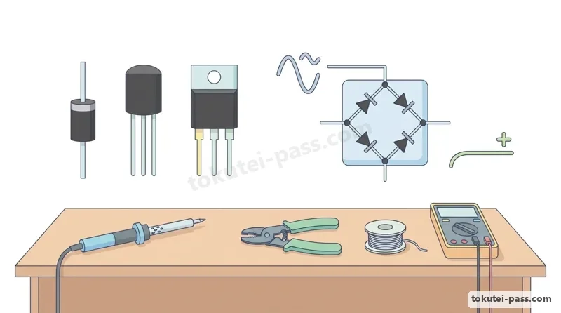
問5は必ず三相交流回路の計算問題です。Y結線(星形)では線電流Ilと相電流Ipが等しく(Il=Ip)、線間電圧Vlは相電圧Vpの√3倍(Vl=√3×Vp、よってVp=Vl÷√3)になります。
Question 5 is always a three-phase AC calculation problem. In a star (Y) connection, line current Il equals phase current Ip (Il = Ip), and line-to-line voltage Vl is √3 times phase voltage Vp (Vl = √3 × Vp, so Vp = Vl ÷ √3).
一方、Δ結線(環状・デルタ)では線間電圧Vlと相電圧Vpが等しく(Vl=Vp)、線電流Ilは相電流Ipの√3倍(Il=√3×Ip)になります。三相電力Pはどちらの結線でも「P=√3×Vl×Il×cosθ=3×Ip²×R(W)」です。
In a delta (Δ) connection, line-to-line voltage Vl equals phase voltage Vp (Vl = Vp), and line current Il is √3 times phase current Ip (Il = √3 × Ip). In either connection, three-phase active power P is "P = √3 × Vl × Il × cosθ = 3 × Ip² × R (W)".
第一種で特に重要なテクニックが「Δ-Y等価変換」です。1相あたりRΔ(Ω)の抵抗3個をΔ結線した負荷は、抵抗値を「3分の1(RY=RΔ÷3)」にしたY結線負荷と完全に等価になります(逆にY結線からΔ結線に変えると電流と電力は3倍になります)。
An essential First-Class shortcut is "Δ-Y equivalent conversion." Three resistors of RΔ (Ω) per phase connected in Δ are completely equivalent to a Y-connected load whose resistance per phase is "one-third (RY = RΔ ÷ 3)" (conversely, switching a load from Y to Δ triples both line current and power).
この変換を使えば、電線路に抵抗rがある回路や、Y結線負荷とΔ結線負荷が並列につながった複合回路でも、Δ結線を「RY=RΔ÷3」のY結線に置き換えて1相分の等価回路で簡単に線電流Ilを計算できます。
Using this conversion, even when a circuit includes line resistance r or combines a Y load and a Δ load in parallel, you can replace the Δ load with an equivalent Y load of "RY = RΔ ÷ 3" and easily compute the line current Il using a single-phase equivalent circuit.
Key points
- Y結線は「Vp=Vl÷√3、Il=Ip」、Δ結線は「Vp=Vl、Il=√3×Ip」、三相電力は「P=√3×Vl×Il×cosθ=3×Ip²×R」。
Y connection: "Vp = Vl ÷ √3, Il = Ip"; Δ connection: "Vp = Vl, Il = √3 × Ip"; 3-phase power: "P = √3 × Vl × Il × cosθ = 3 × Ip² × R". - Δ-Y等価変換:Δ結線のインピーダンスZΔは、1/3の値「ZY=ZΔ÷3」のY結線に置き換えることができる。
Δ-Y equivalent conversion: A Δ-connected impedance ZΔ can be replaced by a Y-connected impedance of one-third its value: "ZY = ZΔ ÷ 3". - 1相の抵抗RのY結線負荷とΔ結線負荷を同じ電源Vに並列接続すると、Δ側にはY側の3倍の線電流が流れ、合計線電流は「4V÷(√3R)」となる。
When a Y load (R per phase) and a Δ load (R per phase) are connected in parallel across line voltage V, the Δ load draws 3 times the line current of the Y load, giving a total line current of "4V ÷ (√3R)". - 【例】線間電圧 V = 200V の三相電源に、1相 R = 8Ω、XL = 6Ω(Z = 10Ω)の Y結線負荷を接続 → 相電圧 Vp = 200 ÷ 1.73 ≈ 115.6V、線電流 Il = 115.6 ÷ 10 ≈ 11.6A、抵抗Rの電圧 VR = 11.6 × 8 ≈ 92.5V
Example: A 3-phase source of line voltage V = 200V feeds a Y load with R = 8Ω and XL = 6Ω (Z = 10Ω) per phase → Phase voltage Vp = 200 ÷ 1.73 ≈ 115.6V, line current Il = 115.6 ÷ 10 ≈ 11.6A, voltage across R is VR = 11.6 × 8 ≈ 92.5V
| Word | Meaning |
|---|---|
| Y結線(星形結線) | Y connection (star connection) |
| Δ結線(三角結線) | Δ connection (delta connection) |
| Δ-Y等価変換(RY=RΔ÷3) | Δ-Y equivalent conversion (RY = RΔ ÷ 3) |
| 三相消費電力 | three-phase power consumption |
試験によく出るポイントと覚え方
Key Exam Points & How to Remember
問1のコンデンサ計算では、「1μF=10⁻⁶F」と「1mm=10⁻³m」の単位換算が勝負の分かれ目です。静電エネルギー「W=0.5×C×V²」では0.5を掛け忘れた2倍の数値が必ず選択肢にあるため注意しましょう。
In Question 1 capacitor calculations, unit conversion of "1μF = 10⁻⁶F" and "1mm = 10⁻³m" is the deciding factor. For electrostatic energy "W = 0.5 × C × V²", the choices always include a distractor that forgets the 0.5 factor (twice the true value), so stay alert.
問4の「ダイオード1個を使った半波整流回路」は超頻出のサービス問題です。波形の上半分しか通らないため、消費電力Pは通常の交流回路(V²÷R)のちょうど半分「P=V²÷(2R)」になると即答してください。
The "half-wave rectifier circuit with one diode" in Question 4 is a frequent bonus question. Because only the top half of the waveform passes through, immediately answer that power consumption P is half that of a normal AC circuit: "P = V² ÷ (2R)".
問5の三相交流では、文字式で電力Pや電流Iを問う問題もよく出ます。Δ結線の1相インピーダンスが「Z=√(R²+X²)」のとき、相電流は「Ip=V÷Z」、全消費電力は「P=3×Ip²×R=3V²R÷(R²+X²)」となります。
In Question 5 on three-phase AC, symbolic formula questions for power P or current I are also common. When one phase of a Δ load has impedance "Z = √(R² + X²)", phase current is "Ip = V ÷ Z" and total 3-phase power is "P = 3 × Ip² × R = 3V²R ÷ (R² + X²)".
Key points
- コンデンサの公式3点セット:電界「E=V÷d(V/m)」、電荷「Q=CV(C)」、静電エネルギー「W=0.5CV²(J)」。
Three core capacitor formulas: Electric field "E = V ÷ d (V/m)", Charge "Q = CV (C)", Electrostatic energy "W = 0.5CV² (J)". - ブリッジ平衡条件:向かい合う対辺の抵抗の積が等しい「R1×R4=R2×R3」のとき、中央の電流は0Aになる。
Bridge balance condition: When opposite resistor products are equal "R1 × R4 = R2 × R3", current in the center branch is 0 A. - 周波数fが50Hz→60Hz(1.2倍)になると、コイルのXLは「1.2倍」、コンデンサのXCは「1÷1.2倍」に変化する。
When frequency f changes from 50Hz → 60Hz (1.2×), coil reactance XL "increases by 1.2×" and capacitor reactance XC "decreases by 1 ÷ 1.2×". - 半波整流回路の鉄則:ダイオード1個を入れると、抵抗Rの消費電力は半分の「P=V²÷(2R)」になる。
Half-wave rectifier rule: Inserting one series diode cuts the power consumed by resistor R in half to "P = V² ÷ (2R)". - Δ-Y変換の鉄則:Δ結線の抵抗RΔは「RY=RΔ÷3」のY結線と等価であり、同じ抵抗ならΔ結線はY結線の3倍の電流・電力になる。
Δ-Y conversion rule: Resistance RΔ in delta equals "RY = RΔ ÷ 3" in star; for identical resistors, delta draws 3 times the line current and power of star.
| Word | Meaning |
|---|---|
| 単位換算(μF・mm) | unit conversion (μF, mm) |
| 半波整流の電力(V²÷2R) | half-wave rectifier power (V² ÷ 2R) |
| 直列共振と並列共振 | series resonance and parallel resonance |
| 1相分等価回路 | per-phase equivalent circuit |
Basic Electrical Theory
Practice this chapter in the appOfficial references
- 一般財団法人 電気技術者試験センター「第一種電気工事士学科試験 出題範囲・出題例(1. 電気に関する基礎理論)」 — https://www.shiken.or.jp/construction/first/department/
- 経済産業省「電気工事士法施行規則 第10条(第一種電気工事士試験の科目)」 — https://www.meti.go.jp/policy/safety_security/industrial_safety/sangyo/electric/