
Generators, Transformers, Motors, Electrical Applications, and Sequence Control
発電機・変圧器・電動機・電気応用とシーケンス制御
Class 1 Electrician 第一種電気工事士 (written exam) · 第一種電気工事士(学科試験) · Written by Tokutei Pass based on the official study texts; not copied verbatim.
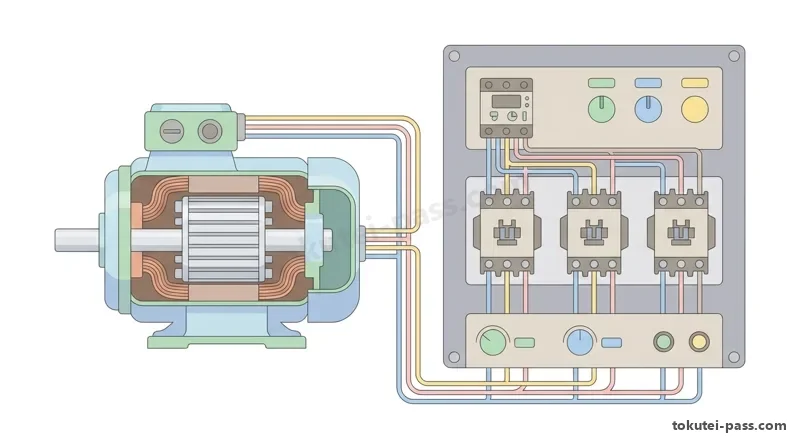
三相かご形誘導電動機の回転速度と始動法
Rotational Speed and Starting Methods of Three-Phase Squirrel-Cage Induction Motors
工場やビルの動力設備で広く使われる三相かご形誘導電動機では、固定子巻線に三相交流を流すと回転磁界が生じます。この速度を同期速度 Ns(min⁻¹)と呼び、電源周波数 f(Hz)と極数 p から Ns = 120 × f ÷ p で求まります。
In a three-phase squirrel-cage induction motor (三相かご形誘導電動機), which is the most widely used motor in factory and building power equipment, supplying three-phase AC current to the stator (固定子) windings generates a rotating magnetic field (回転磁界). The speed of this rotating magnetic field is called the synchronous speed Ns (min⁻¹), calculated from the power supply frequency f (Hz) and number of magnetic poles p as Ns = 120 × f ÷ p.
回転子の実際の回転速度 N(min⁻¹)は同期速度 Ns より少し遅くなり、その速度差の割合を滑り s = (Ns − N) ÷ Ns と定義します。よって回転速度は N = Ns × (1 − s) = (120 × f ÷ p) × (1 − s) となり、周波数 f にほぼ比例します。
The actual rotational speed N (min⁻¹) of the rotor (回転子) is slightly slower than the synchronous speed Ns, and the ratio of this speed difference is defined as slip (滑り) s = (Ns − N) ÷ Ns. Therefore, the rotational speed is N = Ns × (1 − s) = (120 × f ÷ p) × (1 − s), changing almost in direct proportion to the frequency f.
インバータ(VVVF:可変電圧可変周波数制御装置)を用い、電圧 V と周波数 f の比(V ÷ f)を一定に保ちながら周波数を変えると、磁束を一定に保って効率よく速度制御できます。60Hz から 50Hz 等へ変えたときの回転速度計算が頻出です。
By using an inverter (インバータ — VVVF: Variable Voltage Variable Frequency controller) to continuously vary the frequency while keeping the ratio of voltage V to frequency f (V ÷ f) constant, the rotational speed can be controlled efficiently without saturating the magnetic flux. Exam questions frequently ask you to calculate the rotational speed N when the frequency is changed from 60Hz to 50Hz or 45Hz.
かご形誘導電動機を直接電源につなぐ全電圧始動(じか入れ始動)では、定格電流の 5〜8倍の始動電流が流れます。大容量機では始動電流を抑えるため、始動時にスター(Y)結線、加速後にデルタ(Δ)結線へ切り替える Y-Δ 始動法が採用されます。
In full-voltage starting (全電圧始動 — direct-on-line starting じか入れ始動), where a squirrel-cage induction motor is connected directly to the power source, a large starting current (始動電流) of 5 to 8 times the rated current flows. For large-capacity motors, to suppress the starting current, the star-delta (Y-Δ始動法) starting method is used: the stator windings are connected in star (Y) during starting and switched to delta (Δ) after acceleration.
Y-Δ 始動法では、各相巻線の電圧が全電圧始動(Δ結線)の 1 ÷ √3 倍になるため、電源側の始動電流(線電流)と始動トルクはともに全電圧始動時の 1 ÷ 3 に減少します。なお二次抵抗始動法は巻線形専用であり、かご形には使えません。
In Y-Δ starting, the voltage applied to each phase winding becomes 1 ÷ √3 times that of full-voltage starting (Δ connection), so both the line current on the supply side (starting current) and the starting torque (始動トルク) decrease to 1 ÷ 3 (approximately 33%) of their full-voltage starting values. Note that secondary resistance starting (二次抵抗始動法) is exclusively for wound-rotor induction motors (巻線形誘導電動機) and cannot be used for squirrel-cage motors.
Key points
- 同期速度 Ns = 120 × f ÷ p(min⁻¹)、実回転速度 N = Ns × (1 − s)。4極・50Hz なら Ns = 1,500 min⁻¹、60Hz なら Ns = 1,800 min⁻¹
Synchronous speed Ns = 120 × f ÷ p (min⁻¹), actual rotational speed N = Ns × (1 − s). For 4 poles: Ns = 1,500 min⁻¹ at 50Hz, and Ns = 1,800 min⁻¹ at 60Hz - Y-Δ 始動法では、全電圧始動に比べて相電圧が 1 ÷ √3 倍、始動電流(線電流)と始動トルクはともに 1 ÷ 3 倍になる
In Y-Δ starting, compared to full-voltage starting, phase voltage is 1 ÷ √3 times, while both starting current (line current) and starting torque become 1 ÷ 3 times - かご形の始動法は全電圧始動・Y-Δ始動・リアクトル始動・始動補償器法であり、二次抵抗始動法は巻線形専用
Starting methods for squirrel-cage motors include direct-on-line, Y-Δ, reactor, and autotransformer starting; secondary resistance starting is exclusively for wound-rotor motors - 高効率のトップランナーモータ(IE3)へ更新すると、定格効率と回転速度は上がるが、始動電流は従来機より大きくなる点に注意
When upgrading to a high-efficiency Top Runner motor (IE3), rated efficiency and rotational speed increase, but be careful that the starting current is larger than in conventional motors
| Word | Meaning |
|---|---|
| 同期速度 | 同期速度 (どうきそくど): Synchronous speed (Ns = 120f ÷ p) |
| 滑り | 滑り (すべり): Slip (s = (Ns − N) ÷ Ns) |
| かご形誘導電動機 | かご形誘導電動機 (かごがたゆうどうでんどうき): Squirrel-cage induction motor |
| スター・デルタ始動 | スター・デルタ始動 (しどう): Star-delta (Y-Δ) starting |
| インバータ制御 | インバータ制御 (せいぎょ): Inverter control (VVVF) |
| 巻線形誘導電動機 | 巻線形誘導電動機 (まきせんがたゆうどうでんどうき): Wound-rotor induction motor |
変圧器の損失・最大効率条件と耐熱クラス
Transformer Losses, Maximum Efficiency Condition, and Thermal Classes
変圧器の損失は、負荷に無関係で一定の無負荷損(鉄損 Pi)と、負荷電流(負荷率 m)の 2乗に比例する負荷損(銅損 Pc)に分けられます。鉄損はヒステリシス損と渦電流損から成り、ケイ素鋼板やアモルファス合金鉄心で低減されます。
Transformer (変圧器) losses are divided into two types: no-load loss (無負荷損 — iron loss 鉄損 Pi), which occurs at a constant rate regardless of load size, and load loss (負荷損 — copper loss 銅損 Pc), which increases in proportion to the square of the load current (or the square of the load factor m). Iron loss consists of hysteresis loss (ヒステリシス損) and eddy-current loss (渦電流損), and is reduced by using silicon steel sheets (ケイ素鋼板) or amorphous alloys (アモルファス合金) for the iron core.
定格容量 Pn(W)の変圧器を負荷率 m(0 ≦ m ≦ 1)、力率 cosθ で運転するときの出力は Pout = m × Pn × cosθ で、銅損は全負荷銅損 Pc0 から m² × Pc0 となります。効率 η は Pout ÷ (Pout + Pi + m² × Pc0) × 100(%)です。
When a transformer with rated capacity Pn (W) is operated at a load factor m (0 ≤ m ≤ 1) and power factor cosθ, its output is Pout = m × Pn × cosθ, and the copper loss at that time is expressed using the full-load copper loss Pc0 as m² × Pc0. Therefore, the efficiency η is calculated by Pout ÷ (Pout + Pi + m² × Pc0) × 100 (%).
変圧器の効率 η が最大となるのは、無負荷損(鉄損 Pi)と運転時の負荷損(銅損 m² × Pc0)が等しくなるとき、すなわち Pi = m² × Pc0 のときです。これより最大効率となる負荷率 m は m = √(Pi ÷ Pc0) で求められます。
The efficiency η of a transformer reaches its maximum when the no-load loss (iron loss Pi) equals the operating load loss (copper loss m² × Pc0), that is, when Pi = m² × Pc0. From this, the load factor m at maximum efficiency is found by m = √(Pi ÷ Pc0), which appears almost every year as a calculation problem.
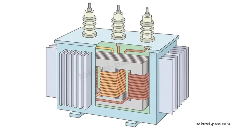
ビル等の受電室では、絶縁油を使わず高圧巻線をエポキシ樹脂で固めた難燃性のモールド変圧器が多用されます。写真鑑別では、上部の太いブスバーが低圧二次端子、細いがいし端子が高圧一次端子、中央の切替片がタップ端子です。
In receiving rooms of buildings and hospitals, flame-retardant cast-resin transformers (モールド変圧器), in which high-voltage windings are encapsulated in epoxy resin (エポキシ樹脂) without using insulating oil, are widely used. In photo identification questions, distinguish that the thick busbars at the top are the low-voltage secondary terminals (低圧二次端子), the thin insulator terminals are the high-voltage primary terminals (高圧一次端子), and the link plates near the center are the tap terminals (タップ端子) for voltage adjustment.
変圧器や電動機の絶縁材料は最高許容温度により耐熱クラス(JIS C 4003)が定まっています。低い順に Y(90℃)< A(105℃)< E(120℃)< B(130℃)< F(155℃)< H(180℃)< C(180℃超)となり、E・B・F・H が頻出です。
Furthermore, insulating materials of transformers and motors are classified into thermal classes (耐熱クラス — JIS C 4003) according to their maximum permissible temperature. In ascending order of permissible temperature, they are Y (90℃) < A (105℃) < E (120℃) < B (130℃) < F (155℃) < H (180℃) < C (over 180℃); the order and temperatures of E, B, F, and H are especially frequent on the exam.
Key points
- 無負荷損(鉄損 Pi = ヒステリシス損 + 渦電流損)は負荷に無関係で一定、負荷損(銅損)は負荷電流(負荷率 m)の 2乗に比例
No-load loss (iron loss Pi = hysteresis loss + eddy-current loss) is constant regardless of load; load loss (copper loss) is proportional to the square of load current (load factor m) - 最大効率条件は「鉄損 Pi = 運転時の銅損 m² × Pc0」であり、最大効率時の負荷率は m = √(Pi ÷ Pc0)
The maximum efficiency condition is Iron loss Pi = Operating copper loss m² × Pc0, and the load factor at maximum efficiency is m = √(Pi ÷ Pc0) - モールド変圧器はエポキシ樹脂絶縁で難燃性・保守容易だが、油入変圧器に比べて価格は高め
Cast-resin transformers use epoxy resin insulation, offering flame retardancy and easy maintenance, though they are more expensive than oil-immersed transformers - 絶縁材料の耐熱クラス:Y(90℃)< A(105℃)< E(120℃)< B(130℃)< F(155℃)< H(180℃)< C(180℃超)
Thermal classes of insulating materials: Y (90℃) < A (105℃) < E (120℃) < B (130℃) < F (155℃) < H (180℃) < C (over 180℃)
| Word | Meaning |
|---|---|
| 無負荷損(鉄損) | 無負荷損・鉄損 (むふかそん・てつそん): No-load loss / Iron loss (Pi) |
| 負荷損(銅損) | 負荷損・銅損 (ふかそん・どうそん): Load loss / Copper loss (Pc) |
| ヒステリシス損 | ヒステリシス損 (そん): Hysteresis loss |
| 渦電流損 | 渦電流損 (うずでんりゅうそん): Eddy-current loss |
| モールド変圧器 | モールド変圧器 (へんあつき): Cast-resin (molded) transformer |
| 耐熱クラス | 耐熱クラス (たいねつくらす): Thermal class (Y, A, E, B, F, H, C) |
照明・電熱計算と特殊場所用機器
Lighting, Electric Heating Calculations, and Special Location Equipment
照明工学の 4つの基本量は単位とセットで暗記します。光源から出る光の総量が光束 F(lm ルーメン)、特定方向への光の強さが光度 I(cd カンデラ)、照らされる面の明るさが照度 E(lx ルクス)、光源や反射面の輝きが輝度 L(cd/m²)です。
Memorize the four fundamental quantities of lighting engineering together with their units. The total amount of light emitted from a light source is luminous flux F (光束, unit: lm lumen), the strength of light in a specific direction is luminous intensity I (光度, cd candela), the brightness of an illuminated surface is illuminance E (照度, lx lux), and the brilliance (glare) of a light source or reflecting surface is luminance L (輝度, cd/m²).
LED は半導体の p-n 接合に電流を流して直接発光させるエレクトロルミネセンス(EL)を応用し、紫外線を蛍光体に当てる蛍光ランプ(ホトルミネセンス)とは原理が異なります。また断熱材施工天井には S形(SB・SG形)ダウンライトを選定します。
LED lamps utilize electroluminescence (エレクトロルミネセンス — EL), passing current through a semiconductor p-n junction to emit light directly, which differs in principle from fluorescent lamps (photoluminescence ホトルミネセンス) that shine ultraviolet rays onto phosphor. Also, for ceilings with thermal insulation construction, select S-type (SB-type, SG-type) recessed downlights designed for insulated ceilings.
電熱器で水 m(kg)を温度差 Δt(K)だけ加熱するとき、比熱 4.2 kJ/(kg・K)、熱効率 η、1kWh = 3,600kJ とすると、電力量 W(kWh)= (4.2 × m × Δt) ÷ (3,600 × η) です。エコキュートの冷媒には CO₂ を使います。
When heating a mass m (kg) of water by a temperature difference Δt (℃ or K) with an electric heater, taking the specific heat of water as 4.2 kJ/(kg·K), thermal efficiency as η (decimal), and electrical energy 1kWh = 3,600kJ, the required electrical energy W (kWh) is found by W = (4.2 × m × Δt) ÷ (3,600 × η). In natural refrigerant heat pump water heaters (エコキュート — EcoCute), carbon dioxide (CO₂) is used as the refrigerant.
工業用電気加熱では、交番磁束による渦電流で金属を溶かす誘導加熱、高周波電界で木材やプラスチックなど絶縁物を内部から均一に温める誘電加熱、ヒータからの電磁波で塗装面等の表面を乾かす赤外線加熱の区別が重要です。
In industrial electric heating, it is important to distinguish between induction heating (誘導加熱), which melts metals using eddy currents induced by alternating magnetic flux; dielectric heating (誘電加熱 — the principle of microwave ovens), which heats insulators such as wood and plastics uniformly from the inside using a high-frequency electric field; and infrared heating (赤外線加熱), which dries surfaces with electromagnetic waves from heaters placed slightly away from the heated object.
写真鑑別では、可燃性ガス等が存在する危険場所で使う厚いガラスグローブと保護網付きの防爆形照明器具や、大電流導体を鋼製ダクト内に絶縁支持して工場幹線に使うバスダクトがよく出題されます。
In photo identification of factory equipment, explosion-proof luminaires (防爆形照明器具) equipped with robust glass globes and protective guards for use in hazardous locations containing flammable gases or vapors, and bus ducts (バスダクト) that support large-current conductors (copper or aluminum) with insulators inside a steel duct for factory trunk lines, frequently appear on the exam.
Key points
- 光束=ルーメン(lm)、光度=カンデラ(cd)、照度=ルクス(lx)、輝度=cd/m²。LED はエレクトロルミネセンス(定格寿命約 40,000時間)
Luminous flux = lumen (lm), Luminous intensity = candela (cd), Illuminance = lux (lx), Luminance = cd/m². LEDs use electroluminescence (rated life approx. 40,000 hours) - 水加熱の電力量 W(kWh)= 4.2 × m(kg)× Δt(K)÷ (3,600 × η)。1 kWh = 3,600 kJ の換算を忘れないこと
Electrical energy for water heating W (kWh) = 4.2 × m (kg) × Δt (K) ÷ (3,600 × η). Do not forget the conversion 1 kWh = 3,600 kJ - 金属(導体)の溶解は渦電流による「誘導加熱」、木材・プラスチック(絶縁物)の内部加熱は「誘電加熱」
Melting metals (conductors) via eddy currents is induction heating (誘導加熱); internal heating of wood and plastics (insulators) is dielectric heating (誘電加熱) - エコキュートの冷媒は CO₂(二酸化炭素)。断熱天井には S形(SB・SG形)ダウンライト、危険場所には防爆形照明器具を使用
EcoCute refrigerant is CO₂ (carbon dioxide). Use S-type (SB, SG) downlights for insulated ceilings, and explosion-proof luminaires (防爆形照明器具) for hazardous locations
| Word | Meaning |
|---|---|
| 光束・光度・照度・輝度 | 光束・光度・照度・輝度: Luminous flux (lm), intensity (cd), illuminance (lx), luminance (cd/m²) |
| エレクトロルミネセンス | エレクトロルミネセンス: Electroluminescence (LED operating principle) |
| 誘導加熱 | 誘導加熱 (ゆうどうかねつ): Induction heating (heating conductors via eddy currents) |
| 誘電加熱 | 誘電加熱 (ゆうでんかねつ): Dielectric heating (heating insulators via high-frequency fields) |
| 防爆形照明器具 | 防爆形照明器具 (ぼうばくがたしょうめいきぐ): Explosion-proof luminaire |
| バスダクト | バスダクト: Bus duct (enclosed busbar trunking system) |
蓄電池設備とパワーエレクトロニクス
Storage Battery Systems and Power Electronics
受電設備の操作用直流電源等には蓄電池(二次電池)が使われます。鉛蓄電池は正極に二酸化鉛(PbO₂)、負極に鉛(Pb)、電解液に希硫酸(H₂SO₄)を用い、公称電圧は約 2.0V/セルです。放電が進むと両極が硫酸鉛になり電解液比重が低下します。
Secondary batteries (二次電池 / 蓄電池) are used for emergency power supplies and DC control power supplies in receiving substations. A lead-acid battery (鉛蓄電池) uses lead dioxide (PbO₂) for the positive plate, spongy lead (Pb) for the negative plate, and dilute sulfuric acid (希硫酸 H₂SO₄) for the electrolyte, with a nominal voltage of about 2.0V/cell. As discharging progresses, both electrodes turn into lead sulfate (PbSO₄) and the specific gravity of the electrolyte decreases.
一方、アルカリ蓄電池(ニッケル・カドミウム蓄電池等)は正極に水酸化ニッケル、負極にカドミウム、電解液に水酸化カリウム水溶液(KOH)を用い、公称電圧は約 1.2V/セルです。過放電や低温に強く長寿命という特徴があります。
On the other hand, an alkaline storage battery (アルカリ蓄電池, such as a nickel-cadmium battery) uses nickel hydroxide for the positive plate, cadmium for the negative plate, and an aqueous potassium hydroxide solution (水酸化カリウム水溶液 KOH) for the electrolyte, with a nominal voltage of about 1.2V/cell. Compared to lead-acid batteries, it is more resistant to over-discharging and low temperatures and has a longer service life.
直流電源装置の浮動充電方式は、充電器(整流器)・蓄電池・負荷の 3つをすべて並列接続する方式です。平常時は蓄電池の自己放電を補いつつ負荷へ給電し、停電時には無瞬断で蓄電池から負荷へ給電します。
The floating charge system (浮動充電方式) of a DC power supply unit connects the charger (rectifier), storage battery, and load all in parallel. During normal operation, the charger supplies power to the load while compensating for the self-discharge of the storage battery; during a power outage, power supply to the load switches from the battery without any interruption (無瞬断).
電力変換器では、交流を直流に変えるのがコンバータ、直流を交流に変えるのがインバータ、直流を別の直流電圧に変えるのがチョッパです。サイリスタのゲート信号で制御角 α を遅らせる位相制御では波形の一部が切り取られます。
In power electronics, organize the names of converters: a converter (コンバータ / 順変換器) changes AC to DC, an inverter (インバータ / 逆変換器) changes DC to AC, and a DC-DC converter (チョッパ — chopper) changes one DC voltage to another DC voltage. In phase control (位相制御), where a pulse is applied to the gate of a thyristor to delay the conduction start angle (control angle α), the output waveform has a portion of each half-cycle chopped off.
またポンプや送風機をインバータで速度制御すると、流量 Q は回転速度 N の 1乗、圧力 H は N の 2乗、消費電力(軸動力 P)は N の 3乗に比例するため、減速で大きな省エネ効果が得られます。
Furthermore, when the rotational speed of a pump or fan (送風機) is controlled by an inverter, the flow rate (air volume Q) is proportional to the 1st power of rotational speed N, pressure (head H) is proportional to the 2nd power of N, and shaft power (power consumption P) is proportional to the 3rd power of N. Therefore, even a slight reduction in rotational speed yields substantial energy savings.
Key points
- 鉛蓄電池は希硫酸・約 2.0V/セル(放電で比重低下)、アルカリ蓄電池は水酸化カリウム水溶液・約 1.2V/セル
Lead-acid battery = dilute sulfuric acid, approx. 2.0V/cell (specific gravity drops on discharge); Alkaline battery = aqueous KOH solution, approx. 1.2V/cell - 浮動充電方式は「充電器・蓄電池・負荷」をすべて並列接続し、常時微小充電しながら負荷へ給電する
Floating charge system connects Charger, Storage battery, and Load all in parallel, supplying the load while continuously trickle-charging the battery - コンバータ=交流→直流、インバータ=直流→交流、チョッパ=直流→直流。サイリスタはゲート信号で点弧角を制御
Converter = AC → DC, Inverter = DC → AC, Chopper = DC → DC. A thyristor controls the firing angle using a gate signal - ポンプ・ファンのインバータ制御:流量 Q ∝ N、揚程 H ∝ N²、消費電力(軸動力)P ∝ N³(3乗に比例)
Inverter control of pumps and fans: Flow rate Q ∝ N, Head H ∝ N², Power consumption (shaft power) P ∝ N³ (proportional to the cube of speed)
| Word | Meaning |
|---|---|
| 鉛蓄電池 | 鉛蓄電池 (なまりちくでんち): Lead-acid storage battery (2.0V/cell, dilute H₂SO₄) |
| アルカリ蓄電池 | アルカリ蓄電池 (ちくでんち): Alkaline storage battery (1.2V/cell, aqueous KOH) |
| 浮動充電方式 | 浮動充電方式 (ふどうじゅうでんほうしき): Floating charge system |
| コンバータ・インバータ | コンバータ・インバータ: Converter (AC→DC) and Inverter (DC→AC) |
| サイリスタ位相制御 | サイリスタ位相制御 (いそうせいぎょ): Thyristor phase control |
シーケンス制御①:接点図記号と自己保持回路
Sequence Control 1: Contact Symbols and Self-Holding Circuits
電動機を制御するシーケンス回路は毎年必出です。JIS C 0617 の接点記号として、操作しないとき開いており操作すると閉じる「a接点(メーク接点・常開接点)」と、操作しないとき閉じており操作すると開く「b接点(ブレーク接点・常閉接点)」を見分けましょう。
Sequence control circuits (シーケンス制御回路) that start, stop, and automatically operate electric motors are an essential topic appearing every year on the First-Class Electrician written exam. First, among JIS C 0617 contact symbols, reliably distinguish between an a-contact (a接点 / メーク接点 / 常開接点 — Normally Open), which is open when unactuated and closes when actuated, and a b-contact (b接点 / ブレーク接点 / 常閉接点 — Normally Closed), which is closed when unactuated and opens when actuated.
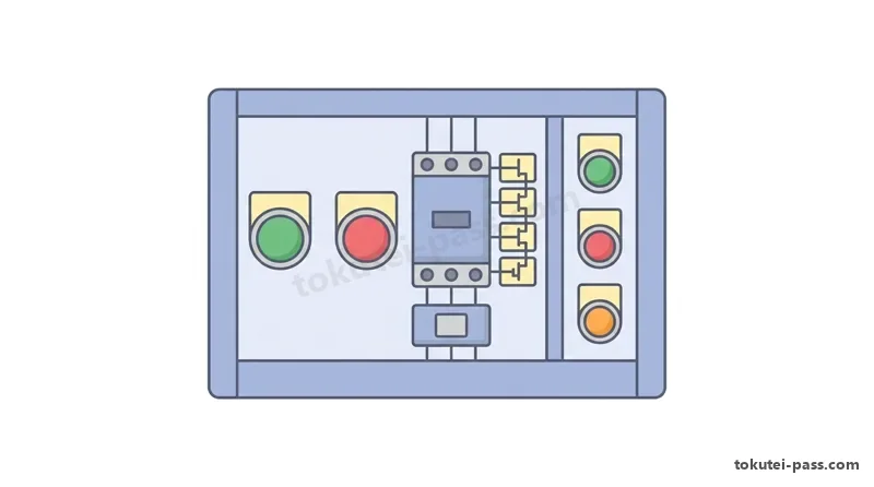
縦書きのシーケンス図では、縦線の右側に可動部が離れているのが a接点、左側で接触しているのが b接点です。押しボタンは T字形の頭、電磁接触器(MC)の補助接点は半円形のリンク記号、熱動継電器(THR)は四角い箱形要素が付きます。
In vertically drawn sequence diagrams, a movable contact drawn detached to the right of the vertical line is an a-contact, whereas one touching on the left side of the vertical line is a b-contact. A pushbutton (押しボタン) has a T-shaped head at the tip of the rod, an auxiliary contact of an electromagnetic contactor (電磁接触器 MC) has a semicircular link symbol, and a thermal relay (サーマルリレー THR) has a square box-shaped trip element.
押しボタンは指を離すと戻るため、始動用押しボタン BS(a接点)に電磁接触器の補助 a接点(MC-a)を「並列」に接続します。これにより BS を一瞬押すだけでコイル MC が励磁され続け、指を離しても運転を保つ「自己保持回路」となります。
Because a pushbutton returns to its original position when you release your finger, an auxiliary self-holding a-contact (MC-a) of the electromagnetic contactor is connected in parallel (並列) with the start pushbutton BS (a-contact). As a result, pressing BS for just a moment keeps the contactor coil MC energized, forming a self-holding circuit (自己保持回路) that maintains the running state even after the button is released.
自己保持を解除する停止用押しボタン(b接点)や、過負荷時に遮断するサーマルリレー接点 THR(b接点)は、自己保持回路およびコイル MC に対して必ず「直列」に挿入します。いずれかが開くとコイル電流が途切れて安全に停止します。
The stop pushbutton (b-contact) used to release self-holding and stop the motor, as well as the thermal relay contact THR (b-contact) that interrupts the circuit during an overload, must always be inserted in series (直列) with the self-holding circuit and coil MC. When either opens, current to coil MC is cut off, and the main contacts and self-holding contact open simultaneously for a safe stop.
2か所以上の場所から始動・停止を行う複数箇所操作回路では、「始動用 a接点(ONボタン)どうしは並列(OR回路)」、「停止用 b接点(OFFボタン)どうしは直列(AND回路)」に接続するのが絶対の鉄則です。
In a multi-point control circuit (複数箇所操作回路) that starts and stops equipment from two or more locations, the absolute ironclad rule is: connect start a-contacts (ON buttons) in parallel with each other (OR circuit), and connect stop b-contacts (OFF buttons) in series with each other (AND circuit).
Key points
- a接点(メーク接点)は常時開(右開き)、b接点(ブレーク接点)は常時閉(左閉じ)
An a-contact (make contact) is normally open (opens to the right); a b-contact (break contact) is normally closed (closes on the left) - 自己保持回路:始動ボタン(a接点)と電磁接触器の補助 a接点(MC-a)を並列にし、停止ボタン(b接点)と THR(b接点)を直列にする
Self-holding circuit: connect the start button (a-contact) and contactor auxiliary a-contact (MC-a) in parallel, and connect the stop button (b-contact) and THR (b-contact) in series - 複数箇所から操作する場合:始動ボタン(a接点)はすべて並列接続、停止ボタン(b接点)はすべて直列接続
When operating from multiple locations: connect all start buttons (a-contacts) in parallel, and connect all stop buttons (b-contacts) in series - サーマルリレー(THR)が動作すると THR の b接点が開き電動機を停止させ、THR の a接点が閉じて故障表示灯(OL など)を点灯させる
When the thermal relay (THR) trips, its THR b-contact opens to stop the motor, and its THR a-contact closes to light the fault indicator lamp (such as OL)
| Word | Meaning |
|---|---|
| a接点(メーク接点) | a接点・メーク接点 (せってん): a-contact / Make contact (Normally Open - NO) |
| b接点(ブレーク接点) | b接点・ブレーク接点 (せってん): b-contact / Break contact (Normally Closed - NC) |
| 自己保持回路 | 自己保持回路 (じこほじかいろ): Self-holding (latching) circuit |
| 電磁接触器(MC) | 電磁接触器 (でんじせっしょくき - MC): Electromagnetic contactor (MC) |
| 熱動継電器(THR) | 熱動継電器 (ねつどうけいでんき - THR): Thermal relay (THR) |
シーケンス制御②:正逆転インターロックとタイマ回路
Sequence Control 2: Forward-Reverse Interlock and Timer Circuits
三相誘導電動機を逆転させるには、主回路の三相 3本(R・S・T)のうち「いずれか 2本の接続を入れ替え」て回転磁界の向きを逆にします。3本すべてを順番に入れ替えても相回転の順が同じになり逆転しないため注意しましょう。
To reverse the direction of rotation of a three-phase induction motor, swap the connections of any two of the three phases (R, S, T or U, V, W) in the main circuit to reverse the direction of the rotating magnetic field. Be careful that if you shift all three wires in cyclic order, the phase sequence remains the same and the motor will not reverse.
正転用電磁接触器(MCF)と逆転用電磁接触器(MCR)が同時投入されると、主回路で相間短絡が起きて危険です。これを防ぐため、正転コイル MCF と直列に相手側の MCR-b 接点を入れ、逆転コイル MCR と直列に MCF-b 接点を入れる「インターロック回路」を設けます。
If the forward electromagnetic contactor (MCF or MC1) and reverse electromagnetic contactor (MCR or MC2) were ever closed simultaneously, a dangerous phase-to-phase short circuit would occur in the main circuit. To prevent this, an interlock circuit (インターロック回路 / 相互鎖錠回路) is provided by placing the opposite reverse auxiliary b-contact (MCR-b) in series with the forward coil MCF, and the forward auxiliary b-contact (MCF-b) in series with the reverse coil MCR.
設定時間後に動作する限時継電器(タイマ TLR)では、励磁後に一定時間遅れて閉じる「オンディレイ a接点」や、遅れて開く「オンディレイ b接点」が使われます。図記号では遅れる動作方向に傘マーク(半円弧)を描きます。
In a time-delay relay (限時継電器 / タイマ TLR) whose contacts operate after a set time, an on-delay a-contact (限時動作・瞬時復帰 a接点) that closes a fixed time after coil excitation and an on-delay b-contact that opens a fixed time after excitation are used. In schematic symbols, a rounded umbrella mark (semicircular arc) is drawn pointing in the direction the contact moves (the delayed direction).
Y-Δ 始動回路では、始動時に主接触器(MCM)・スター用(MCS)・タイマ(TLR)が同時励磁されて Y結線で始動します。設定時間後にタイマの限時 b接点で MCS を切り、限時 a接点でデルタ用(MCD)を投入して Δ運転へ移行します。MCS と MCD 間にもインターロックを組みます。
In a Y-Δ starting circuit, pressing the start button simultaneously energizes the main contactor (MCM), star contactor (MCS), and timer (TLR) to start the motor in Y-connection. After the set time, the timer's delayed b-contact opens to de-energize MCS, and its delayed a-contact closes to energize the delta contactor (MCD), transitioning to normal Δ-connected operation. An interlock is always installed between MCS and MCD as well.
制御盤の表示灯では、赤色灯(RL)が運転表示(MC の a接点で点灯)、緑色灯(GL)が停止表示(MC の b接点で点灯)、橙色灯等(OL・WL)が過負荷故障表示(THR の a接点で点灯)として結線されます。タイムチャートを追跡する問題も頻出です。
For indicator lamps on control panels, a red lamp (RL) is generally wired for running indication (lit by MC's a-contact), a green lamp (GL) for stopped indication (lit by MC's b-contact), and an orange or white lamp (OL, WL) for overload fault indication (lit by THR's a-contact). Exam questions frequently ask you to trace time charts (タイムチャート) and lamp states.
Key points
- 三相誘導電動機の逆転は、三相 3本のうち「2本を入れ替える」
To reverse a three-phase induction motor, swap 2 of the 3 wires in the three-phase main circuit - インターロック回路:同時投入による短絡防止のため、自分のコイルと直列に「相手側の b接点」を入れる
Interlock circuit: to prevent a short circuit from simultaneous closing, connect the opposite contactor's b-contact in series with each coil - オンディレイタイマ(TLR):励磁後に設定時間だけ遅れて動作し、消磁すると瞬時に元に戻る(傘マークの向きに注目)
On-delay timer (TLR): operates after a set time delay following excitation, and resets instantaneously when de-energized (pay attention to the direction of the umbrella mark) - Y-Δ 始動回路はタイマでスター用(MCS)からデルタ用(MCD)へ自動切替し、MCS と MCD の同時投入をインターロックで防ぐ
A Y-Δ starting circuit uses a timer to automatically switch from the star contactor (MCS) to the delta contactor (MCD), with an interlock preventing MCS and MCD from closing together
| Word | Meaning |
|---|---|
| 正逆転運転 | 正逆転運転 (せいぎゃくてんうんてん): Forward-reverse operation |
| インターロック回路 | インターロック回路 (かいろ): Interlock circuit |
| 限時継電器(タイマ) | 限時継電器・タイマ (げんじけいでんき): Time-delay relay / Timer (TLR) |
| 限時動作瞬時復帰接点 | 限時動作瞬時復帰接点: On-delay (timed-close/open, instantaneous-reset) contact |
| タイムチャート | タイムチャート: Time chart |
試験によく出るポイントと覚え方
Key Exam Points and Memory Tricks
電動機と変圧器の計算は 3つの公式で解けます。①回転速度 N = (120 × f ÷ p) × (1 − s)、②Y-Δ 始動は「始動電流もトルクも全電圧始動の 1 ÷ 3」、③変圧器最大効率は m = √(Pi ÷ Pc0) です。
Motor and transformer calculation problems can be solved completely with 3 formulas: (1) Rotational speed N = (120 × f ÷ p) × (1 − s); (2) In Y-Δ starting, both starting current and starting torque are 1 ÷ 3 of full-voltage starting; (3) Maximum transformer efficiency occurs when Iron loss Pi = Operating copper loss m² × Pc0, meaning m = √(Pi ÷ Pc0).
耐熱クラスの順番は「Y(90℃)・A(105℃)・E(120℃)・B(130℃)・F(155℃)・H(180℃)・C(180℃超)」で暗記しましょう。特に E(120℃)→ B(130℃)→ F(155℃)→ H(180℃)の温度入替ひっかけが頻出です。
Memorize the thermal class order as: Y (90℃) → A (105℃) → E (120℃) → B (130℃) → F (155℃) → H (180℃) → C (over 180℃). Watch out for frequent exam traps that swap the temperatures among E (120℃) → B (130℃) → F (155℃) → H (180℃).
照明単位は「光束=lm、光度=cd、照度=lx、輝度=cd/m²」です。電熱では「金属=渦電流による誘導加熱」「絶縁物=高周波電界による誘電加熱」と漢字 1文字(導と電)の違いを正確に見分けてください。
Lighting units are: Luminous flux = lumen (lm), Luminous intensity = candela (cd), Illuminance = lux (lx), and Luminance = cd/m². For electric heating, accurately distinguish the single kanji difference: Metals = Induction heating (誘導加熱) via eddy currents, whereas Insulators = Dielectric heating (誘電加熱) via high-frequency electric fields.
シーケンスの空欄補充は、①始動ボタンと並列は「自分の補助 a接点(自己保持)」、②同時投入防止でコイルと直列は「相手の補助 b接点(インターロック)」、③複数箇所の始動は「a接点並列」・停止は「b接点直列」で解けます。
Fill-in-the-blank sequence control problems can be solved with 3 principles: (1) Connected in parallel with the start button is its own auxiliary a-contact (self-holding); (2) Connected in series with a coil that must never close simultaneously with the other side is the opposite side's auxiliary b-contact (interlock); (3) Multi-point start uses parallel a-contacts, while multi-point stop uses series b-contacts.
Key points
- Y-Δ 始動=始動電流 1 ÷ 3・始動トルク 1 ÷ 3、最大効率負荷率 m = √(鉄損 ÷ 全負荷銅損)
Y-Δ starting = 1 ÷ 3 starting current and 1 ÷ 3 starting torque; Maximum efficiency load factor m = √(Iron loss ÷ Full-load copper loss) - 耐熱クラス「Y(90)・A(105)・E(120)・B(130)・F(155)・H(180)・C(180超)」と照明単位「光束 lm・光度 cd・照度 lx・輝度 cd/m²」
Thermal classes Y(90), A(105), E(120), B(130), F(155), H(180), C(over 180) and lighting units: flux lm, intensity cd, illuminance lx, luminance cd/m² - 鉛蓄電池=希硫酸 2.0V、アルカリ蓄電池=KOH 1.2V、ポンプ消費電力 P ∝ 回転速度 N³
Lead-acid battery = dilute H₂SO₄ 2.0V; Alkaline battery = KOH 1.2V; Pump power consumption P ∝ rotational speed N³ - シーケンス 3原則:自己保持は「自分の a接点並列」、インターロックは「相手の b接点直列」、複数停止は「b接点直列」
3 Sequence Principles: Self-holding = own a-contact in parallel; Interlock = opposite b-contact in series; Multi-point stop = b-contacts in series
| Word | Meaning |
|---|---|
| 最大効率条件 | 最大効率条件 (さいだいこうりつじょうけん): Maximum efficiency condition (Pi = m² × Pc0) |
| 耐熱クラス(Y・A・E・B・F・H・C) | 耐熱クラス (Y・A・E・B・F・H・C): Thermal insulation classes |
| 自己保持とインターロック | 自己保持とインターロック: Self-holding and Interlock |
Electrical Machines, Applications & Sequence Control
Practice this chapter in the appOfficial references
- 一般財団法人 電気技術者試験センター — 第一種電気工事士 試験問題と解答 — https://www.shiken.or.jp/situation/past_exam.html
- 日本産業規格 JIS C 0617 — 電気用図記号 / JIS C 4003 — 電気絶縁の熱的耐久性評価及び呼び — https://www.jisc.go.jp/