
Reading Single-Line Diagrams and Control Circuit Diagrams
単線結線図・制御回路図の読図
Class 1 Electrician 第一種電気工事士 (written exam) · 第一種電気工事士(学科試験) · Written by Tokutei Pass based on the official study texts; not copied verbatim.
高圧受電設備の単線結線図と機器の配置順序
Single-Line Diagrams of High-Voltage Receiving Equipment and Equipment Arrangement Order
第一種電気工事士の筆記試験では、後半の問31から問50までの20問(40点分)が「自家用電気工作物の配線図問題」として出題されます。
In the Class 1 Electrician written exam, the last 20 questions from Question 31 to Question 50 (worth 40 points) are presented as wiring diagram questions on private electrical installations.
その中心となるのが、6.6kV高圧受電設備(キュービクル等)の単線結線図と、低圧動力制御回路の読図です。
The core of this section is reading single-line diagrams of 6.6kV high-voltage power receiving equipment (such as cubicles) and low-voltage motor control circuits.
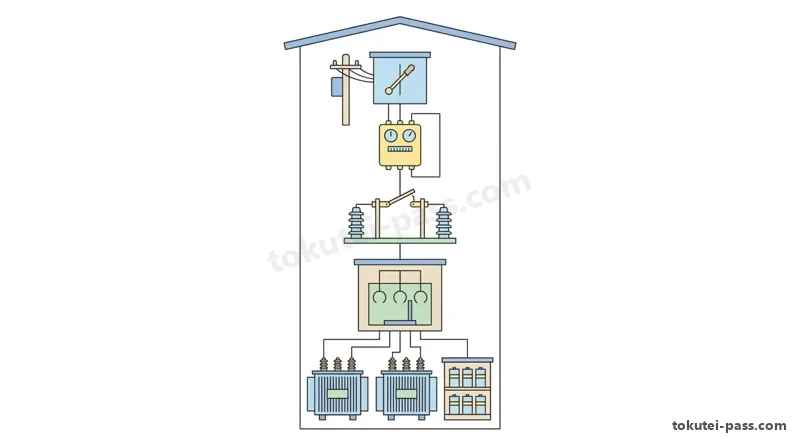
単線結線図を読むときは、電源側(引込柱)から負荷側(低圧分電盤)へ向かう電気の流れと機器の配置順序を正確に把握します。
When reading a single-line diagram, accurately grasp the flow of electricity and the arrangement order of equipment from the power source side (Pole No. 1) toward the load side (low-voltage distribution board).
①責任分界点:第1号柱の「GR付PAS(地絡継電装置付高圧交流負荷開閉器)」または地中引込用の「UGS」に設けられます。
① Demarcation Point of Responsibility: Installed at the Pole-mounted High-Voltage AC Load Break Switch with Ground Relay (PAS with GR) on Pole No. 1 for overhead drops, or at the Underground Disconnecting Switch (UGS) for underground service.
PASやUGSには零相変流器(ZCT)が内蔵され、地絡方向継電器(DGR)と連動して構内の地絡事故を遮断し、波及事故を防ぎます。
A Zero-Phase Current Transformer (ZCT) is built into the PAS or UGS and operates in conjunction with a Directional Ground Relay (DGR) to trip internal ground faults and prevent fault propagation to the utility grid.
②引込高圧ケーブル〜受電点:6600V CVTケーブル等で終端接続部(ケーブルヘッドCH)を介してキュービクルへ引き込み、最初に電力需給用計器用変成器(VCTまたはMOF)および取引メータである電力量計(Wh)を接続します。
② High-Voltage Service Cable to Receiving Point: Power is drawn into the cubicle via a 6600V CVT cable through a cable head (CH), connecting first to the Combined Metering Transformer (VCT or MOF) and the utility watt-hour meter (Wh).
Key points
- 責任分界点にはGR付PAS(架空引込)またはUGS(地中引込)が設置され、ZCTとGR(またはDGR)で地絡保護を行う
At the demarcation point of responsibility, a PAS with GR (overhead drop) or UGS (underground drop) is installed to provide ground-fault protection using a ZCT and GR (or DGR) - VCT(MOF)は取引メータ(電力量計Wh)用の変成器であり、断路器(DS)や遮断器(CB)より電源側に配置されることが多い
The VCT (MOF) is a combined instrument transformer for the utility billing watt-hour meter (Wh) and is usually placed on the source side ahead of the disconnecting switch (DS) and circuit breaker (CB) - 避雷器(LA)は高圧母線の電源側に断路器(DS)を介して接続され、A種接地工事(接地線14mm²以上)を施す
A lightning arrester (LA) is connected to the source side of the high-voltage busbar via a disconnecting switch (DS) and must be grounded with Class A grounding (grounding conductor 14mm² or larger)
| Word | Meaning |
|---|---|
| 単線結線図 | tansen kessenzu (single-line diagram): a simplified diagram representing a three-phase power circuit with a single line to show the sequence and connection of equipment |
| 責任分界点 | sekinin bunkaiten (demarcation point of responsibility): the boundary dividing maintenance and safety responsibility between the electric power company and the private consumer |
| 地絡継電装置付高圧交流負荷開閉器 | chiraku keiden sōchitsuki kōatsu kōryū fuka kaiheiki (PAS with GR): a pole-mounted high-voltage AC load break switch equipped with a ground-fault relay system |
| 電力需給用計器用変成器 | denryoku jukyūyō keikiyō henseiki (VCT / MOF - combined metering transformer): a single unit housing voltage transformers (VT) and current transformers (CT) for utility revenue metering |
| 高圧受電設備 | kōatsu juden setsubi (high-voltage power receiving equipment): cubicle or substation equipment that receives 6.6kV power from the utility grid and steps it down to 100V/200V |
主遮断装置(CB形・PF・S形)と変圧器・進相コンデンサ回路
Main Circuit Breakers (CB Type vs. PF-S Type), Transformers, and Power Capacitor Circuits
③主遮断装置:受電設備容量300kVA超では「CB形」として、断路器(DS)+真空遮断器(VCB)+変流器(CT)+過電流継電器(OCR)を用います。
③ Main Circuit Breaker Unit: For receiving capacities over 300kVA, the CB type is used, consisting of a Disconnecting Switch (DS) + Vacuum Circuit Breaker (VCB) + Current Transformer (CT) + Overcurrent Relay (OCR).
受電設備容量300kVA以下の簡易受電設備では「PF・S形」として、限流ヒューズ付高圧交流負荷開閉器(LBS+PF)を主遮断装置に用います。
For simplified receiving equipment of 300kVA or less, the PF-S type is used as the main interrupting device, consisting of a High-Voltage AC Load Break Switch with Current-Limiting Power Fuses (LBS + PF).
④計器用変成器:高圧母線の電圧を110Vに降圧する計器用変圧器(VT)には、1次側に2本の電力ヒューズ(PF)を設けます。
④ Instrument Transformers: The Voltage Transformer (VT), which steps down the high-voltage bus voltage to 110V, is protected on its primary side by two Power Fuses (PF).
⑤変圧器分岐回路:LBS(PF付)または高圧カットアウト(PC)を経由して、三相変圧器(3φT:動力用)や単相変圧器(1φT:電灯用)へ接続します。
⑤ Transformer Branch Circuits: Connected via an LBS (with PF) or High-Voltage Cutout (PC) to a three-phase transformer (3φT for motor power) or a single-phase transformer (1φT for lighting).
変圧器の低圧側中性点(または1端子)には、高低圧混触時の電位上昇を防ぐため「B種接地工事(EB)」が必ず施されます。
Class B grounding work (EB) is always applied to the low-voltage neutral point (or one terminal) of the transformer to prevent potential rise during a high-to-low voltage contact fault.
⑥力率改善回路:LBS(PF付)またはPCの下流に、放電コイル(DC)内蔵の進相コンデンサ(SC)と、その電源側に高調波抑制用の直列リアクトル(SR)を接続します。
⑥ Power Factor Correction Circuit: Downstream of an LBS (with PF) or PC, a Static Capacitor (SC) with a built-in Discharge Coil (DC) is connected, along with a Series Reactor (SR) on the source side of the SC to suppress harmonics.
Key points
- 主遮断装置のCB形は「DS+VCB(またはCB)+CT+OCR」、PF・S形は「高圧交流負荷開閉器(LBS)+電力ヒューズ(PF)」で構成される
A CB-type main breaker consists of DS + VCB (or CB) + CT + OCR, whereas a PF-S-type main breaker consists of a High-Voltage AC Load Break Switch (LBS) + Power Fuses (PF) - 高圧進相コンデンサ(SC)の電源側には第5調波対策および突入電流抑制用の直列リアクトル(SR:容量6%)を直列接続する
A Series Reactor (SR: 6% reactance capacity) is connected in series on the power source side of the High-Voltage Static Capacitor (SC) to suppress 5th harmonics and limit inrush current - 単線結線図で変圧器の2次側から引き出された接地(EB)はB種接地工事、機器外箱やCT・VT2次側の接地(EA・ED)はA種またはD種接地工事
In a single-line diagram, grounding drawn from the transformer secondary (EB) is Class B grounding, while equipment enclosure and CT/VT secondary grounding (EA, ED) is Class A or Class D grounding
| Word | Meaning |
|---|---|
| 主遮断装置 | shushadan sōchi (main interrupting device / main breaker): the primary protective switching assembly that isolates the entire high-voltage installation during a short-circuit fault |
| 真空遮断器 | shinkū shadanki (VCB - vacuum circuit breaker): a high-voltage circuit breaker that extinguishes arcs inside high-vacuum interrupter bottles, offering compactness and long life |
| 高圧交流負荷開閉器 | kōatsu kōryū fuka kaiheiki (LBS - high-voltage AC load break switch): a switch capable of making and breaking normal load current, combined with power fuses (PF) to interrupt short-circuit currents |
| 高圧カットアウト | kōatsu kattoauto (PC - high-voltage porcelain cutout): a compact fuse-holder switch used for small transformers (300kVA or less) or capacitor bank branches |
| 直列リアクトル | chokuretsu riakutoru (SR - series reactor): an inductor connected in series on the source side of a power capacitor (SC) to prevent 5th harmonic waveform distortion and reduce switching inrush current |
JIS C 0617 図記号と略号の完全整理
Complete Guide to JIS C 0617 Graphical Symbols and Abbreviations
配線図問題では、単線結線図中の図記号や略号から、機器の名称・写真・役割を答える問題が毎年必ず出題されます。
In the wiring diagram section, questions asking for the name, photograph, and function of equipment from its graphical symbol or abbreviation in the single-line diagram appear every single year.
開閉器・遮断器類の図記号は、接点部分(可動部と固定部)のマークで区別します。丸印(○)があれば負荷電流を開閉できる開閉器(LBS・PAS)です。
Switches and circuit breakers are distinguished by the mark at the contact point (between the moving and fixed blades): a circle (○) indicates a load break switch capable of switching load current (LBS, PAS).
バツ印(×)があれば故障電流(短絡電流)を遮断できる遮断器(VCB・CB・MCCB)であり、横棒(―)のみは電流を開閉できない断路器(DS)です。
An X mark (×) indicates a circuit breaker capable of interrupting fault (short-circuit) current (VCB, CB, MCCB), whereas a simple horizontal bar (―) alone indicates a disconnecting switch (DS) that cannot switch load current.
変成器類の図記号は、高圧母線を貫通する丸または半円と斜線で表されます。ZCTは三相一括貫通、CTは各相貫通(通例2相分)です。
Current transformer symbols are drawn as a circle or semicircle passing around the high-voltage busbar with diagonal slashes: a ZCT encloses all three phases together, while a CT is installed per phase (usually on 2 phases).
VTは変圧器と同じ2つの円が重なる記号(または巻線記号)で高圧母線から分岐し、ZVT(EVT)は3個の巻線と接地記号で表されます。
A VT is represented by two overlapping circles (or winding symbols) branching off the high-voltage busbar just like a transformer, while a ZVT (EVT) is shown as three windings with a ground symbol.
直列リアクトル(SR)はコンデンサ(SC)の直前に描かれるインダクタンス記号で、放電コイル(DC)はSCに並列に接続される三角印または巻線記号です。
A Series Reactor (SR) is drawn as an inductance symbol immediately ahead of the capacitor (SC), and a Discharge Coil (DC) is drawn as a triangle or winding connected in parallel across the SC.
Key points
- 接点記号の見分け方:「―(横棒)」=断路器(DS)、「○(丸)」=負荷開閉器(LBS・PAS)、「×(バツ)」=遮断器(VCB・CB・MCCB)
How to distinguish contact symbols: horizontal bar (―) = Disconnecting Switch (DS); circle (○) = Load Break Switch (LBS, PAS); cross (×) = Circuit Breaker (VCB, CB, MCCB) - 主要略号:LA(避雷器)、VCT/MOF(電力需給用計器用変成器)、VMC(高圧真空電磁接触器)、PC(高圧カットアウト)
Key abbreviations: LA (Lightning Arrester), VCT/MOF (Combined Metering Transformer), VMC (High-Voltage Vacuum Magnetic Contactor), PC (High-Voltage Cutout) - コンデンサ周辺の略号:SC(高圧進相コンデンサ)、SR(高圧直列リアクトル)、DC(放電コイル)
Capacitor bank abbreviations: SC (High-Voltage Static Capacitor), SR (High-Voltage Series Reactor), DC (Discharge Coil)
| Word | Meaning |
|---|---|
| 図記号 | zukigō (graphical symbol): standard schematic symbols defined by JIS C 0617 used to represent electrical devices on wiring diagrams |
| 断路器 | danroki (DS - disconnecting switch): an isolating switch used to create a visible open gap during maintenance; it has no arc chute and must never open or close load current |
| 高圧真空電磁接触器 | kōatsu shinkū denji sesshokuki (VMC - high-voltage vacuum magnetic contactor): an electromagnetically operated vacuum switch suited for frequent switching of high-voltage motors or capacitors |
| 零相変流器 | reisō henryūki (ZCT - zero-phase current transformer): a ring-type current transformer surrounding all three phase conductors to detect zero-phase (ground-fault) current |
| 放電コイル | hōden koiru (DC - discharge coil): a coil connected in parallel with a power capacitor (SC) to safely discharge residual voltage within 5 seconds (or 3 minutes) after disconnection |
制御器具番号と保護継電器・試験器・計器類
Control Device Numbers (JEM 1038), Protective Relays, Testers, and Meters
単線結線図内の四角枠や丸枠に書かれた数字は「制御器具番号(JEM 1038)」であり、番号と略号・名称の対応は暗記必須です。
Numbers written inside squares or circles on a single-line diagram are Control Device Numbers (JEM 1038); memorizing the correspondence between numbers, abbreviations, and names is mandatory.
電流・地絡系:「51」=過電流継電器(OCR、CTに接続)、「67」=地絡方向継電器(DGR、ZCTとZVTの両方に接続)、「64」=地絡過電圧継電器(OVGR)。
Current and ground-fault relays: 51 = Overcurrent Relay (OCR, connected to CT); 67 = Directional Ground Relay (DGR, connected to both ZCT and ZVT); 64 = Ground Overvoltage Relay (OVGR).
電圧・温度・遮断器系:「27」=不足電圧継電器(UVR、VTに接続)、「59」=過電圧継電器(OVR)、「49」=熱動継電器(THR)、「26」=温度継電器、「52」=交流遮断器(VCB)。
Voltage, thermal, and breaker numbers: 27 = Undervoltage Relay (UVR, connected to VT); 59 = Overvoltage Relay (OVR); 49 = Thermal Relay (THR); 26 = Transformer Temperature Relay; 52 = AC Circuit Breaker (VCB).
計器切替開閉器:CTの2次側には電流計(A)と「電流計切替開閉器(AS)」、VTの2次側には電圧計(V)と「電圧計切替開閉器(VS)」を設けます。
Meter selector switches: On the CT secondary side, an ammeter (A) and Ammeter Switch (AS) are provided; on the VT secondary side, a voltmeter (V) and Voltmeter Switch (VS) are provided.
保護継電器の動作試験を行うため、CT回路には「電流試験端子(CTT)」、VT回路には「電圧試験端子(VTT)」が設けられます。
To perform operating tests on protective relays, a Current Test Terminal (CTT) is installed in the CT circuit, and a Voltage Test Terminal (VTT) is installed in the VT circuit.
試験時には、CTTやVTTに「過電流継電器試験器(OCR試験器)」や「地絡方向継電器試験器(DGR試験器)」を接続して整定値と動作時間を確認します。
During testing, an Overcurrent Relay Tester (OCR tester) or Directional Ground Relay Tester (DGR tester) is connected to the CTT and VTT to verify relay pickup settings and operating times.
Key points
- 頻出制御器具番号:27=UVR(不足電圧)、49=THR(熱動)、51=OCR(過電流)、52=VCB(遮断器)、59=OVR(過電圧)、64=OVGR(地絡過電圧)、67=DGR(地絡方向)
Frequently tested Control Device Numbers: 27 = UVR (Undervoltage), 49 = THR (Thermal), 51 = OCR (Overcurrent), 52 = VCB (Circuit Breaker), 59 = OVR (Overvoltage), 64 = OVGR (Ground Overvoltage), 67 = DGR (Directional Ground) - CT回路にはA(電流計)・AS(電流計切替開閉器)・CTT(電流試験端子)・OCR(51)が接続される
The CT secondary circuit connects to A (Ammeter), AS (Ammeter Selector Switch), CTT (Current Test Terminal), and OCR (51) - VT回路にはV(電圧計)・VS(電圧計切替開閉器)・VTT(電圧試験端子)・UVR(27)やOVR(59)が接続される
The VT secondary circuit connects to V (Voltmeter), VS (Voltmeter Selector Switch), VTT (Voltage Test Terminal), and UVR (27) or OVR (59)
| Word | Meaning |
|---|---|
| 制御器具番号 | seigyo kigu bangō (control device number): standard JEM 1038 function numbers identifying protective relays, breakers, and control devices in substations |
| 電流計切替開閉器 | denryūkei kirikae kaiheiki (AS - ammeter selector switch): a rotary switch allowing a single ammeter to read the current in each of the R, S, and T phases without open-circuiting the CT |
| 電圧計切替開閉器 | den'atsukei kirikae kaiheiki (VS - voltmeter selector switch): a rotary switch allowing a single voltmeter to read line-to-line voltages across R-S, S-T, and T-R |
| 電流試験端子 | denryū shiken tanshi (CTT - current test terminal): a terminal block in the CT secondary circuit used to inject test current into the OCR or replace meters without opening the CT secondary |
| 不足電圧継電器 | fusoku den'atsu keidenki (UVR - undervoltage relay, No. 27): a protective relay that operates when bus voltage drops below a preset threshold or during a power outage |
高圧ケーブル(CVT・KIP)とCT・VTの複線図・開閉手順
High-Voltage Cables (CVT, KIP), CT/VT Multi-Line Diagrams, and Switching Sequence
高圧受電設備の引込線には「6600V架橋ポリエチレン絶縁ビニルシースケーブルトリプレックス形(CVT)」が最も多く使用されます。
For high-voltage service entrance cables, the 6600V Cross-linked Polyethylene Insulated Vinyl Sheathed Triplex Cable (CVT) is the most widely used.
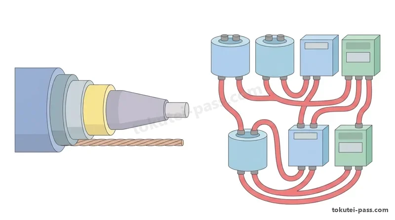
CVTの断面構造は中心から順に、①導体→②内部半導電層→③架橋ポリエチレン絶縁体→④外部半導電層→⑤銅テープ遮へい層→⑥ビニルシースの6層です。
The cross-sectional structure of a CVT cable from the center outward consists of 6 layers: ① Conductor → ② Inner Semiconducting Layer → ③ XLPE Insulation → ④ Outer Semiconducting Layer → ⑤ Copper Tape Shield Layer → ⑥ Vinyl Sheath.
一方、キュービクル内の機器間配線に使う「高圧機器内配線用電線(KIP)」は、①導体→②半導電層→③EPゴム絶縁体の3層構造で遮へい層がありません。
In contrast, High-Voltage Equipment Internal Wire (KIP) used for inter-device wiring inside a cubicle has a 3-layer structure: ① Conductor → ② Semiconducting Layer → ③ EP Rubber Insulation, with no metallic shield layer.
CT(2個)の複線結線図では、1次側極性(Kが電源側、Lが負荷側)に合わせ、2次側(k・l)のl端子(R相とT相)を共通接続してD種接地します。
In the multi-line connection diagram of two CTs, matching the primary polarity (K on source side, L on load side), the secondary l terminals (for R and T phases) are tied together in common and grounded with Class D grounding.
VT(2個)のV-V結線図では、1次側を3相母線(R-S間・S-T間)にPFを介して接続し、2次側の共通端子(v端子)にD種接地工事を施します。
In the V-V connection diagram of two VTs, the primary windings connect to the 3-phase busbars (R-S and S-T) via PFs, and the common secondary terminal (v terminal) receives Class D grounding.
また点検時に停電させる順序は「低圧MCCB切り→VCB切り→DS切り」、復電(投入)順序は「DS入れ→VCB入れ→低圧MCCB入れ」が鉄則です。
Furthermore, the ironclad rule for de-energizing during maintenance is Low-Voltage MCCB OFF → VCB OFF → DS OFF; and for re-energizing (closing), DS ON → VCB ON → Low-Voltage MCCB ON.
Key points
- 6600V CVTケーブルは内部・外部半導電層と銅テープ遮へい層(A種接地)を持つが、KIP(EPゴム絶縁)には遮へい層やシースがない
A 6600V CVT cable has inner/outer semiconducting layers and a copper tape shield (Class A grounding), whereas KIP wire (EP rubber insulation) has no shield layer and no sheath - CT・VTの2次側は絶縁破壊時の高圧侵入防止のためD種接地工事を施し、CTの2次側は通電中に絶対に開放してはならない
The secondary sides of high-voltage CTs and VTs require Class D grounding to prevent high-voltage intrusion if insulation fails, and a CT secondary must never be open-circuited while energized - 断路器(DS)は負荷電流を開閉できないため、遮断時は必ず「VCBを切ってからDSを切る」、投入時は「DSを入れてからVCBを入れる」
Because a Disconnecting Switch (DS) cannot break load current, when opening you must always trip the VCB first before opening the DS; when closing, close the DS first before closing the VCB
| Word | Meaning |
|---|---|
| 架橋ポリエチレン絶縁ビニルシースケーブル | kakyō poriechiren zetsuen biniru shīsu kēburu (CV / CVT cable): a high-voltage XLPE-insulated cable with superior thermal resistance (90°C continuous rating) and low dielectric loss |
| 高圧機器内配線用電線 | kōatsu kikinai haisen'yō densen (KIP wire): flexible ethylene-propylene (EP) rubber insulated high-voltage wire used for internal jumpers inside cubicles |
| 半導電層 | handōdensō (semiconducting layer): thin conductive layers bonded to the inner and outer surfaces of CVT cable insulation to equalize the electric field and prevent corona discharge |
| 銅テープ遮へい層 | dō tēpu shaheisō (copper tape shield layer): a metallic shield wrapped around a high-voltage cable core to carry charging current and fault current safely to earth via Class A grounding |
| 自己融着性テープ | jiko yūchakusei tēpu (self-amalgamating insulating tape): rubber insulating tape used in high-voltage cable terminations that fuses into a void-free homogeneous layer when stretched and wrapped |
動力制御盤(Y-Δ始動・正逆転)と非常用予備発電装置
Motor Control Panels (Y-Δ Starting, Reversing) and Emergency Standby Generators
単線結線図の低圧側にある「動力制御盤」の問題では、三相誘導電動機(3φM)の配線本数や電磁接触器の展開接続図が出題されます。
In questions on the low-voltage Motor Control Panel shown on the single-line diagram, the number of wires to a three-phase induction motor (3φM) and schematic control diagrams of magnetic contactors are tested.
Y-Δ(スター・デルタ)始動法では、電動機の3相各巻線の両端(U・V・WとX・Y・Z)を盤内へ引き出すため、制御盤と電動機間の主回路電線は「6本」(接地線を含め7本)になります。
In Y-Δ (star-delta) starting, because both ends of each of the 3 phase windings (U, V, W and X, Y, Z) are brought out into the control panel, the number of main circuit power conductors between the panel and the motor is 6 wires (7 including the grounding wire).
Y-Δ始動回路には3個の電磁接触器(メイン用MC、スター用MCS、デルタ用MCD)とタイマ(TLR)を使い、MCSとMCDには同時投入防止のb接点インターロックを設けます。
A Y-Δ starter circuit uses 3 magnetic contactors (main MC, star MCS, delta MCD) and a timer (TLR), with normally-closed (b-contact) interlocks wired between MCS and MCD to prevent simultaneous closing.
また「非常用予備発電装置(G)」が接続される単線結線図では、商用電源側遮断器と発電機側遮断器が同時に投入されないよう「インターロック(鎖錠装置)」を設けます。
Additionally, in a single-line diagram connected to an Emergency Standby Generator (G), an interlock (locking device) is installed between the commercial utility breaker and the generator breaker.
これは発電機からの電力が商用配電線へ逆潮流して感電事故を起こすのを防ぐためです。
This prevents both breakers from closing simultaneously, which would cause reverse power flow (backfeed) from the generator into the utility distribution line and endanger line workers.
なお、非常用予備発電装置の工事は「特殊電気工事」であり、第一種電気工事士であっても「特種電気工事資格者」の認定がなければ施工できません。
Note that installation work on an emergency standby generator is Special Electrical Work; even a Class 1 Electrician cannot perform this work without certification as a Special Electrical Work Qualifier.
Key points
- 三相誘導電動機のY-Δ始動器と電動機端子箱を結ぶ主回路電線本数は「6本」(接地線を除く)
The number of main circuit conductors connecting a Y-Δ starter to a three-phase induction motor terminal box is 6 wires (excluding the grounding conductor) - 商用電源と非常用予備発電機(G)の切替開閉器・遮断器間には、同時投入(逆送電)を防ぐインターロックが不可欠
An interlock between the commercial power switch/breaker and the emergency standby generator (G) breaker is essential to prevent simultaneous closing (reverse power transmission) - 最大電力500kW未満の自家用電気工作物であっても、非常用予備発電装置工事とネオン工事には「特種電気工事資格者」が必要
Even in private electrical installations under 500kW, emergency standby generator work and neon work require a certified Special Electrical Work Qualifier
| Word | Meaning |
|---|---|
| 動力制御盤 | dōryoku seigyoban (motor control panel): an enclosure housing MCCBs, magnetic contactors, thermal relays, and pushbuttons to control and protect three-phase motors |
| 展開接続図 | tenkai setsuzokuzu (elementary / schematic control diagram): a circuit diagram separating the main power circuit and the control circuit in functional sequence for easy reading |
| 非常用予備発電装置 | hijōyō yobi hatsuden sōchi (emergency standby generator unit - G): an engine-generator set that automatically starts during a utility outage to supply firefighting and emergency loads |
| 鎖錠装置 | sajō sōchi (interlock / locking device): a mechanical or electrical interlocking mechanism that prevents two switches or breakers from being closed at the same time |
| 特種電気工事資格者 | tokushu denki kōji shikakusha (Special Electrical Work Qualifier): a specialized certification required in addition to an electrician license to perform neon or emergency generator installation work |
試験によく出るポイントと覚え方
Frequently Tested Points and Memory Tips
問31〜50の配線図問題は、出題パターンが非常に定型化されており、覚えるべきポイントを押さえれば18問以上(36点以上)の得点源になります。
The 20 wiring diagram questions from Question 31 to Question 50 follow highly predictable patterns; mastering the rules below turns this section into a 36+ point (18+ correct answers) scoring opportunity.
①接地工事の種別判定:高圧機器の金属外箱・鉄台・LA・CVT遮へい層=「A種(10Ω以下)」、変圧器2次側中性点=「B種」、CT・VTの2次側と300V以下低圧機器=「D種」。
① Grounding Class Identification: High-voltage metal enclosures, iron frames, LA, and CVT cable shields = Class A (10Ω or less); transformer secondary neutral point = Class B; high-voltage CT/VT secondaries and low-voltage equipment 300V or less = Class D.
②制御器具番号の語呂合わせ:「27(不=不足な)UVR」、「49(よく=熱が出る)THR」、「51(こい=過電流)OCR」、「52(ゴツい)VCB」、「59(ごく=過電圧)OVR」、「64(むし=地絡過電圧)OVGR」、「67(ろくな=地絡方向)DGR」。
② Control Device Number Mnemonics: 27 = UVR (Undervoltage), 49 = THR (Thermal), 51 = OCR (Overcurrent), 52 = VCB (Breaker), 59 = OVR (Overvoltage), 64 = OVGR (Ground Overvoltage), 67 = DGR (Directional Ground).
③開閉器の操作順序:「切るときは負荷側(MCCB→VCB→DS)から、入れるときは電源側(DS→VCB→MCCB)から」。DSで負荷電流を切る選択肢は必ず誤りです。
③ Switching Operation Sequence: When opening (turning OFF), work from the load side (MCCB → VCB → DS); when closing (turning ON), work from the source side (DS → VCB → MCCB). Any choice that opens a DS before the VCB is always wrong.
④SC回路の引っかけ:コンデンサ(SC)の電源側に直列に入るのは「直列リアクトル(SR)」、SCに並列に入るのは「放電コイル(DC)」です。
④ Capacitor (SC) Circuit Trap: Connected in series on the source side of the capacitor (SC) is the Series Reactor (SR); connected in parallel across the SC is the Discharge Coil (DC).
⑤検相器の用途:三相回路の相順(R・S・Tの回転方向)を確かめ、電動機の逆回転を防ぐ測定器は「検相器」です。
⑤ Application of Phase Rotation Meter: The measuring instrument used to check phase sequence (R-S-T rotation direction) in a three-phase circuit to prevent reverse motor rotation is the Phase Rotation Meter (検相器).
Key points
- LA(避雷器)と高圧機器外箱はA種接地、変圧器の低圧側1端子(EB)はB種接地、高圧CT・VTの2次側はD種接地
Lightning arresters (LA) and high-voltage metal enclosures use Class A grounding; one terminal of the transformer low-voltage side (EB) uses Class B grounding; high-voltage CT and VT secondaries use Class D grounding - ZCTとZVT(またはEVT)の2つから信号線が入っている継電器は必ず「67:地絡方向継電器(DGR)」である
A protective relay receiving signal lines from both a ZCT and a ZVT (or EVT) is always 67: Directional Ground Relay (DGR) - 制御回路で「自己保持接点」は起動押しボタン(BS1・ON)に並列なa接点、「インターロック接点」は相手側電磁接触器コイルに直列なb接点
In motor control circuits, the self-holding contact is a normally-open (a) contact in parallel with the START pushbutton (BS1/ON), and the interlock contact is a normally-closed (b) contact in series with the opposing contactor coil
| Word | Meaning |
|---|---|
| 地絡方向継電器 | chiraku hōkō keidenki (DGR - directional ground relay, No. 67): a relay that receives zero-phase current from a ZCT and zero-phase voltage from a ZVT to selectively detect internal ground faults |
| 過電流継電器 | kadenryū keidenki (OCR - overcurrent relay, No. 51): a relay fed by a CT that trips the VCB when overload or short-circuit current flows |
| 地絡過電圧継電器 | chiraku kaden'atsu keidenki (OVGR - ground overvoltage relay, No. 64): a relay that detects zero-phase voltage from a ZVT (EVT) during a ground fault |
| 自己保持接点 | jiko hoji setten (self-holding / seal-in contact): an auxiliary normally-open (a) contact wired in parallel with the start button to keep the contactor coil energized after the button is released |
| インターロック接点 | intārokku setten (interlock contact): an auxiliary normally-closed (b) contact wired in series with the opposite contactor coil to prevent two contactors from energizing simultaneously |
HV Single-Line Wiring Diagrams (配線図)
Practice this chapter in the appOfficial references
- 一般財団法人 電気技術者試験センター 第一種電気工事士 学科試験 過去問題 — https://www.shiken.or.jp/situation/past_exam.html
- JISC 日本産業標準調査会 JIS C 0617 電気用図記号 — https://www.jisc.go.jp/