
Wiring Diagrams
配線図
Class 2 Electrician 第二種電気工事士 (written exam) · 第二種電気工事士(学科試験) · Written by Tokutei Pass based on the official study texts; not copied verbatim.
構内電気設備の配線用図記号(JIS C 0303)①:照明・盤類・機器
Graphical Symbols for Interior Wiring (JIS C 0303) ①: Lighting, Panels, and Equipment
学科試験の後半20問(問31〜問50)は「配線図問題」であり、JIS C 0303(構内電気設備の配線用図記号)の暗記がそのまま得点に直結します。
The final 20 questions of the written exam (Questions 31 to 50) are wiring diagram problems, so memorizing the JIS C 0303 graphical symbols directly translates into guaranteed points.
照明器具の図記号では、丸印(○)が白熱灯やLED等の一般照明を表します。傍記文字として「CL」はシーリングライト(天井直付灯)、「DL」はダウンライト(天井埋込灯)、「Ch」はシャンデリアを表します。
Among lighting fixture symbols, an open circle (○) represents a general luminaire (incandescent, LED, etc.). As side notations, CL stands for ceiling light (surface-mounted ceiling fixture), DL stands for downlight (recessed ceiling fixture), and Ch stands for chandelier.
丸印に短い縦線(壁)がついた記号は「壁付灯(ブラケット)」、丸から斜めの引き出し線(またはP傍記)がついたものは「プルスイッチ付照明」です。また、黒丸(●)は「非常用照明器具」、長方形の中に黒丸は「誘導灯」です。
A circle with a short vertical wall line attached represents a wall bracket light, and a circle with a diagonal leader line (or P notation) represents a pull-switch luminaire. A solid black circle (●) indicates an emergency lighting fixture, while a solid black circle inside a rectangle indicates an exit sign (guidance light).
盤類の図記号では、長方形の対角線の片側を黒く塗りつぶしたものが「分電盤」、四角形の四隅に斜線を入れたものが「制御盤」です。また、正方形の中に「×」を書き「PB」と傍記したものは「プルボックス」です。
Among panel board symbols, a rectangle split diagonally with one half shaded black is a distribution board (panelboard), and a rectangle with diagonal lines across all four corners is a control panel. A square containing an × mark with the notation PB is a pull box.
機器・接地の図記号では、丸の中にプロペラ(羽根)を書いたものが「換気扇」、四角の上に半円を重ねて「WHM」と書いたものが「電力量計」、3本の横線(T字が逆に重なった形)が「接地(アース)」を表します。
Among equipment and grounding symbols, a circle containing propeller blades is a ventilating fan, a rectangle topped by a semicircle labeled WHM is a watt-hour meter, and three horizontal lines of decreasing length (an inverted T shape) represent grounding (earth).
Key points
- 照明の傍記:「CL」はシーリングライト、「DL」はダウンライト、「Ch」はシャンデリア
Lighting notations: CL is ceiling light, DL is downlight, and Ch is chandelier - 壁線付き丸はブラケット(壁付灯)、黒丸(●)は非常用照明、長方形に黒丸は誘導灯
A circle on a wall line is a bracket light, a black circle (●) is an emergency light, and a black circle in a rectangle is an exit sign - 分電盤は対角線の片側黒塗り、制御盤は四隅に斜線、PB(×印)はプルボックス
A distribution board has one diagonal half shaded black; a control panel has corner slashes; PB (with an ×) is a pull box - WHMは電力量計、丸に羽根は換気扇
WHM is a watt-hour meter, and a circle with fan blades is a ventilating fan
| Word | Meaning |
|---|---|
| 配線用図記号 | graphical symbols for electrical wiring |
| シーリングライト | ceiling light |
| ダウンライト | downlight (recessed light) |
| 分電盤 | distribution board (panelboard) |
| プルボックス | pull box |
配線用図記号(JIS C 0303)②:点滅器(スイッチ)の傍記表示
Graphical Symbols for Interior Wiring (JIS C 0303) ②: Switch Side Notations
配線図において、小さな黒丸(●)は「点滅器(スイッチ)」を表します。何も文字が書かれていない黒丸は「単極スイッチ(片切スイッチ)」であり、横に書かれた数字やアルファベット(傍記)によって種類を区別します。
On a wiring diagram, a small solid black circle (●) represents a switch. A plain black circle with no accompanying letters is a single-pole switch, while numbers or letters written beside it (side notations) distinguish specialized switch types.
数字の傍記では、「2P」が「2極スイッチ(両切スイッチ)」、「3」が「3路スイッチ」、「4」が「4路スイッチ」です。2か所から照明をON/OFFするときは2個の「3」を使い、3か所以上から操作するときは両端の「3」の間に「4」を入れます。
Among numerical notations, 2P indicates a double-pole switch (disconnects both wires), 3 indicates a 3-way switch, and 4 indicates a 4-way switch. Two 3-way switches (3) are used to turn a light ON/OFF from two locations, and a 4-way switch (4) is placed between two 3-way switches to control a light from three or more locations.
ランプ内蔵スイッチの区別は超頻出です。「H」は「位置表示灯内蔵スイッチ(ホタルスイッチ:照明がOFFのときに緑色に点灯してスイッチの場所を教える)」、「P」は「確認表示灯内蔵スイッチ(パイロットスイッチ:換気扇などがONのときに赤色に点灯する)」です。
Distinguishing indicator-equipped switches is tested constantly: H indicates a location-indicator switch (Hotaru / glow switch: glows green when the light is OFF so you can find the switch in the dark), whereas P indicates a pilot-lamp switch (glows red when a load such as a ventilating fan is ON).
その他の傍記では、「D」が「遅延スイッチ(切った後もしばらく換気扇などが回り続ける)」、「WP」が「防雨形スイッチ(屋外用)」、「R」が「リモコンスイッチ」、「L」が「電磁開閉器用押しボタン」、「A」が「自動点滅器(明暗センサ)」、「LC」が「調光器(ライトコントロール)」です。
Other switch notations include: D for a delayed-off switch (keeps a ventilating fan running briefly after being turned off), WP for a weatherproof (rainproof) switch, R for a remote control switch, L for an electromagnetic contactor pushbutton, A for an automatic photocell switch (daylight sensor), and LC for a dimmer (light control).
Key points
- 黒丸(●)のみは単極スイッチ、「2P」は2極(両切)、「3」は3路、「4」は4路スイッチ
A plain black circle (●) is a single-pole switch; 2P is double-pole; 3 is a 3-way switch; 4 is a 4-way switch - 「H」は位置表示灯内蔵(OFF時に点灯)、「P」は確認表示灯内蔵(ON時に点灯)
H is a location-indicator switch (lit when OFF); P is a confirmation pilot switch (lit when ON) - 「D」は遅延スイッチ、「WP」は防雨形、「R」はリモコンスイッチ
D is a delayed-off switch, WP is weatherproof, and R is a remote control switch - 「A」は自動点滅器(明るさセンサ)、「LC」は調光器(ライトコントロール)
A is an automatic switch (photocell sensor), and LC is a dimmer (light control)
| Word | Meaning |
|---|---|
| 位置表示灯内蔵スイッチ | location-indicator switch (glows when OFF - notation H) |
| 確認表示灯内蔵スイッチ | confirmation pilot-lamp switch (glows when ON - notation P) |
| 遅延スイッチ | delayed-off switch (notation D) |
| 調光器 | dimmer / light control (notation LC) |
配線用図記号(JIS C 0303)③:コンセントと配線・電線管の記号
Graphical Symbols for Interior Wiring (JIS C 0303) ③: Receptacles, Wiring Lines, and Conduits
壁付きの半円ドーム形の記号は「コンセント」を表します(丸の中にドーム形が入ったものは「床コンセント[フロアコンセント]」、黒塗りのドームは「天井付きコンセント」です)。数字の「2」「3」は口数(2口・3口)を表します。
A semicircular dome symbol attached to a wall line represents a receptacle (outlet) (a dome enclosed inside a circle is a floor outlet, and a solid black dome is a ceiling outlet). A number 2 or 3 beside it indicates the number of outlets (duplex or triplex receptacle).
アース関連の傍記は最も重要です。「E」は「接地極付コンセント(差込口にアースピン穴がある)」、「ET」は「接地ターミナル付コンセント(アース線をつなぐねじ端子がある)」、「EET」は「接地極付接地ターミナル付コンセント(両方ある)」です。
Grounding-related notations are the most important: E indicates a grounding-pole receptacle (has a grounding pin slot), ET indicates a grounding-terminal receptacle (has a screw terminal for a ground wire), and EET indicates a receptacle equipped with both a grounding pole and a grounding terminal.
機能・容量の傍記では、「LK」が「抜け止め形」、「T」が「引掛形」、「WP」が「防雨形」、「EL」が「漏電遮断器付」です。また、「20A 250V E」と書かれていれば、エアコン等に使う「20A・250V接地極付コンセント」です。
For function and rating notations: LK is a locking (twist-to-hold) blade receptacle, T is a twist-lock receptacle, WP is a weatherproof receptacle, and EL is a receptacle with a built-in earth leakage breaker. A notation of 20A 250V E denotes a 20A, 250V receptacle with a grounding pole (commonly used for air conditioners).
配線の線種記号では、「実線(―)」が「天井隠ぺい配線または壁内隠ぺい配線」、「破線(― ―)」が「床隠ぺい配線」、「点線(‐‐‐)」が「露出配線」、「一点鎖線(―・―)」が「地中埋設配線」を表します。また、丸から矢印が出る記号は上階への「立ち上がり」、丸に向かって矢印が入る記号は下階への「立ち下がり」です。
For wiring line styles: a solid line (―) indicates concealed ceiling or wall wiring, a long-dash line (― ―) indicates concealed floor wiring, a short-dash dotted line (‐‐‐) indicates exposed wiring, and a dash-dot line (―・―) indicates underground wiring. A circle with an outward-pointing arrow indicates a riser going up to the floor above, while an arrow pointing into a circle indicates a drop going down to the floor below.
電線管の傍記記号では、「VE」が硬質ポリ塩化ビニル電線管、「CD」が合成樹脂製可とう電線管(CD管)、「PF」がPF管、「FEP」が波付硬質合成樹脂管(地中用)、「E」がねじなし電線管、「G」が厚鋼電線管、「C」が薄鋼電線管、「F2」が2種金属製可とう電線管です(例:VE22は呼び22mmのVE管)。
For conduit notations: VE is rigid PVC conduit, CD is non-flame-retardant flexible resin conduit, PF is flame-retardant flexible resin conduit, FEP is corrugated hard polyethylene conduit (for underground use), E is threadless metal conduit, G is thick-wall steel conduit, C is thin-wall steel conduit, and F2 is Type 2 flexible metal conduit (e.g., VE22 means 22mm nominal size VE conduit).
Key points
- コンセントの傍記:「E」は接地極付、「ET」は接地ターミナル付、「EET」は両方付
Receptacle notations: E has a grounding pole, ET has a grounding terminal, and EET has both - 「LK」は抜け止め形、「T」は引掛形、「WP」は防雨形、「EL」は漏電遮断器付
LK is blade-retaining (locking), T is twist-lock, WP is weatherproof, and EL has an earth leakage breaker - 配線の線種:実線=天井・壁隠ぺい、破線=床隠ぺい、点線=露出、一点鎖線=地中配線
Line styles: solid line = concealed ceiling/wall, long dashes = concealed floor, short dashes = exposed, dash-dot = underground - 電線管の記号:VE=硬質ビニル管、FEP=地中用波付管、E=ねじなし管、G=厚鋼管、C=薄鋼管
Conduit symbols: VE = rigid PVC, FEP = underground corrugated resin, E = threadless steel, G = thick steel, C = thin steel
| Word | Meaning |
|---|---|
| 接地極付コンセント | grounding-pole receptacle (notation E) |
| 接地ターミナル | grounding terminal (notation ET) |
| 天井隠ぺい配線 | concealed ceiling wiring |
| 床隠ぺい配線 | concealed floor wiring |
| 露出配線 | exposed wiring |
単線図から複線図への書き換え4ステップ
Four Steps to Convert a Single-Line Diagram into a Multi-Line Diagram
試験の配線図は、電線を1本の線で省略して描いた「単線図」で与えられます。電線の本数やスリーブの刻印を求めるには、実際の心線1本ずつを描き出す「複線図」への書き換えが必要です。複線図は必ず決まった「4ステップ」の順番で描きます。
Exam wiring diagrams are given as single-line diagrams, where each cable run is simplified into a single line. To determine the number of individual wires or ring sleeve stamp marks, you must convert the diagram into a multi-line diagram showing every core conductor using four fixed steps.
【ステップ①】電源の「接地側電線(白線:N)」を、スイッチ以外のすべての「負荷(照明器具・コンセント・換気扇・パイロットランプ)」に接続します(単極スイッチや3路・4路スイッチには白線をつなぎません)。
Step ①: Connect the grounded conductor (white wire: N) from the power source to all loads (lighting fixtures, receptacles, ventilating fans, pilot lamps) except switches (never connect the white wire to single-pole, 3-way, or 4-way switches).
【ステップ②】電源の「非接地側電線(黒線:L)」を、すべての「単極スイッチ」と「コンセント」(および常時点灯のパイロットランプ)に接続します。3路スイッチがある場合は、電源側の3路スイッチの「0番端子」に黒線をつなぎます。
Step ②: Connect the ungrounded conductor (black wire: L) from the power source to all single-pole switches and receptacles (as well as any always-on pilot lamps). If there is a 3-way switch circuit, connect the source black wire to terminal 0 of the source-side 3-way switch.
【ステップ③】単極スイッチの反対側の端子から、同じカタカナ記号(イ・ロ・ハなど)が付いた対応する「照明器具(負荷)」へ線(返り線)をつなぎます。
Step ③: From the opposite terminal of each single-pole switch, draw a switch-leg (return wire) to the corresponding lighting fixture (load) labeled with the matching katakana symbol (イ, ロ, ハ, etc.).
【ステップ④】3路スイッチがある場合は、照明側の3路スイッチの「0番端子」から照明器具へつなぎ、2つの3路スイッチの「1番端子と3番端子」どうしを2本の連絡線でつなぎます(4路スイッチがあるときは、その間の連絡線2本を中継します)。
Step ④: If there are 3-way switches, connect terminal 0 of the load-side 3-way switch to the lighting fixture, and connect terminals 1 and 3 of the two 3-way switches together using two traveler wires (if a 4-way switch is used, route the two pairs of traveler wires through the 4-way switch).
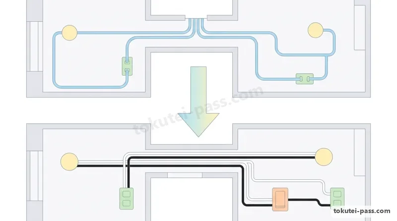
Key points
- ステップ①:電源の接地側(白線)を「照明・コンセント」などの負荷へつなぐ
Step ①: Connect the source grounded wire (white) to all loads (lights and receptacles) - ステップ②:電源の非接地側(黒線)を「スイッチ・コンセント」へつなぐ
Step ②: Connect the source ungrounded wire (black) to all switches and receptacles - ステップ③:スイッチから対応する照明器具(イ・ロ・ハ)へ返り線をつなぐ
Step ③: Connect the return wire from each switch to its matching lighting fixture (イ, ロ, ハ) - ステップ④:3路スイッチは電源黒線と照明を「0番」につなぎ、「1番・3番」どうしを2本で結ぶ
Step ④: For 3-way switches, connect the source black wire and light to terminals 0, and link terminals 1 and 3 with 2 wires
| Word | Meaning |
|---|---|
| 単線図 | single-line diagram |
| 複線図 | multi-line (detailed) wiring diagram |
| 返り線 | switch-leg / return wire (from switch to luminaire) |
| 連絡線 | traveler wires (between 3-way and 4-way switches) |
最少電線本数(心線数)の数え方の法則
Rules for Counting the Minimum Number of Wires (Conductors)
配線図問題で必ず2〜3問出題されるのが「矢印で示された箇所の最少電線本数は何本か」という問題です。複線図を描けば確実に分かりますが、よく出るパターンは法則として覚えておくと一瞬で解けます。
Every wiring diagram section includes 2 to 3 questions asking for the minimum number of wires at an arrow-marked location. Drawing a multi-line diagram always gives the right answer, but memorizing the rules for common patterns lets you solve them instantly.
まず基本として、単相100Vの電源線のみ、照明器具1個のみ、コンセントのみ、単極スイッチ1個のみの配線はすべて「2本」です。
First, as a baseline, a run carrying only a single-phase 100V power feed, only 1 lighting fixture, only a receptacle, or only 1 single-pole switch always requires 2 wires.
単極スイッチが複数並んでいる場合は、黒線(電源)1本を共通で渡り配線し、それぞれのスイッチから返り線が1本ずつ出るため、「スイッチの個数+1本」になります(スイッチ2個なら「3本」、スイッチ3個なら「4本」です)。
When multiple single-pole switches are grouped together, a single black (live) wire is shared via jumpers across all switches while 1 return wire leaves each switch, making the wire count equal to Number of switches + 1 (2 switches = 3 wires; 3 switches = 4 wires).
また、「単極スイッチ1個とコンセント」が同じ場所にある場合は、黒線(共通)・白線(コンセント用)・スイッチの返り線の合計「3本」になります(単極スイッチ2個+コンセントなら「4本」です)。
When 1 single-pole switch and a receptacle are at the same location, they require a black wire (shared), a white wire (for the receptacle), and a switch return wire, totaling 3 wires (2 single-pole switches + a receptacle = 4 wires).
3路・4路スイッチでは、3路スイッチのみへ向かう配線は「3本」(0番・1番・3番)、4路スイッチのみへ向かう配線は「4本」(左右の連絡線2本×2)です。なお、コンセントに「E」や「ET」の傍記があり、ボックスから接地線も一緒に管内を通す場合は、接地線の分として「+1本」を加えます。
For 3-way and 4-way switches, a run going solely to a 3-way switch requires 3 wires (terminals 0, 1, and 3), and a run going solely to a 4-way switch requires 4 wires (two pairs of traveler wires). Note that if a receptacle has an E or ET notation and its grounding wire runs inside the same conduit from the box, add +1 wire for the grounding conductor.
Key points
- 単極スイッチのみが並ぶ配線の最少電線本数は「スイッチの個数+1本」
Minimum wire count for a group of single-pole switches = Number of switches + 1 - 単極スイッチとコンセントが並ぶ配線は「スイッチの個数+2本」(1個+コンセント=3本)
Minimum wire count for single-pole switches plus a receptacle = Number of switches + 2 (1 switch + outlet = 3 wires) - 3路スイッチ単独への配線は「3本」、4路スイッチ単独への配線は「4本」
A run to a single 3-way switch uses 3 wires; a run to a single 4-way switch uses 4 wires - 同じ管内に接地線(アース線)も通す場合は、計算した本数に「+1本」する
If a grounding wire runs inside the same conduit, add +1 wire to the calculated count
| Word | Meaning |
|---|---|
| 最少電線本数 | minimum number of wires (conductors) |
| 渡り配線 | jumper wire (bridging adjacent terminals) |
| 共通線 | common wire |
リモコン配線システム(RT・RR・R)の仕組みと電線本数
Remote Control Wiring System (RT, RR, R) Mechanism and Wire Count
学校やオフィスビルなどで、たくさんの照明を1か所からまとめて操作したり手元で安全に操作したりするときに使われるのが「遠隔操作(リモコン)配線システム」です。構成する3つの機器の役割を理解しましょう。
In schools and office buildings, a remote control wiring system is used to control many lights centrally from one place or operate them safely at low voltage. Make sure you understand the roles of its three component devices.
①「リモコン変圧器(リモコンランス:図記号 RT)」:AC100Vまたは200Vの電源電圧を、安全な「AC24V」の操作用低電圧に降圧する小型変圧器です。
① Remote control transformer (symbol RT): a small step-down transformer that lowers the AC 100V or 200V supply voltage to a safe AC 24V control voltage.
②「リモコンリレー(図記号 RR)」:分電盤やプルボックス内に設置され、24V信号を受けて100V/200Vの照明回路を開閉(ON/OFF)する継電器です。③「リモコンスイッチ(図記号 ●R)」:壁に取り付け、24Vの信号を送る小形スイッチです(集合形の「リモコンセレクタスイッチ」もあります)。
② Remote control relay (symbol RR): installed inside a distribution board or pull box, it receives the 24V control signal and physically switches the 100V/200V main lighting circuit ON and OFF. ③ Remote control switch (symbol ●R): mounted on the wall, this low-voltage switch sends the 24V signal (multi-switch panels are called remote selector switches).
リモコンスイッチ(●R)とリモコンリレー(RR)・変圧器(RT)の間は24Vの小勢力回路となるため、細い通信線や小勢力線で配線でき、その最少電線本数は単極スイッチとまったく同じく「リモコンスイッチの個数+1本」(Rが3個なら4本)になります。
Because the wiring between the remote control switches (●R), relays (RR), and transformer (RT) is a 24V small-power circuit, thin control wires can be used, and the minimum number of wires going to a group of remote switches follows the exact same rule as single-pole switches: Number of remote switches + 1 (e.g., 3 R switches require 4 wires).
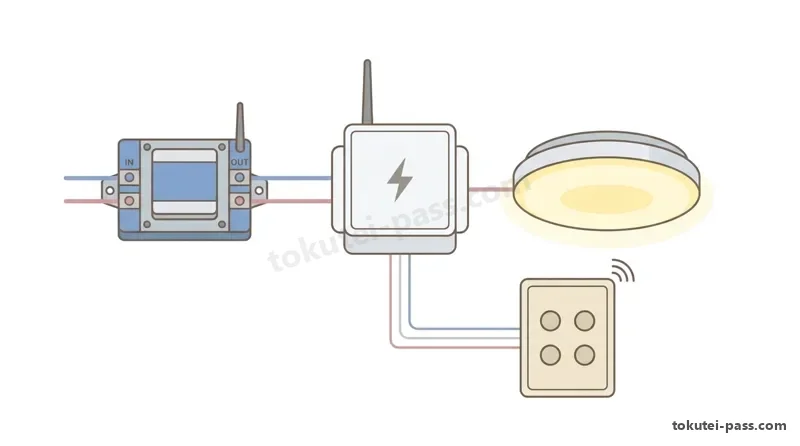
Key points
- リモコン変圧器(RT)は100V/200Vを安全な「AC24V」に降圧する
A remote control transformer (RT) steps 100V/200V down to a safe AC 24V - リモコンリレー(RR)は24V信号を受けて100V/200Vの照明回路を実際にON/OFFする
A remote control relay (RR) receives 24V signals to switch the 100V/200V lighting circuit ON/OFF - リモコンスイッチ(R)は手元で24V回路を操作するスイッチである
A remote control switch (R) is the wall switch used to operate the 24V control circuit - リモコンスイッチへの最少電線本数は「スイッチの個数+1本」で求められる
The minimum number of wires to a group of remote control switches (R) is Number of switches + 1
| Word | Meaning |
|---|---|
| リモコン変圧器 | remote control transformer (100V/200V to 24V - symbol RT) |
| リモコンリレー | remote control relay (symbol RR) |
| リモコンスイッチ | remote control switch (symbol R) |
| リモコンセレクタスイッチ | remote selector switch (multi-switch control panel) |
配線図問題でのリングスリーブ刻印・コネクタ数・使用工具の判定
Determining Ring Sleeve Marks, Connector Counts, and Unused Tools on Diagrams
配線図問題の最後(問48〜問50あたり)では、指定されたボックス内での「リングスリーブの個数と刻印(○・小・中)」または「差込形コネクタ(2本用・3本用・4本用)の組合わせ」が必ず出題されます。
Near the end of the wiring diagram section (around Questions 48 to 50), you will always be asked for the number and stamp marks of ring sleeves (○, 小, 中) or the combination of push-in connectors (2-port, 3-port, 4-port) inside a specified junction box.
これを解くときは、対象のボックスに入ってくるケーブルの太さ(傍記がなければ「VVF1.6mm」、電源幹線などで「2.0」の傍記があれば「VVF2.0mm」)を必ず確認します。その上で複線図を描き、各接続点で何本の電線がつながるかを数えます。
To solve these, first check the cable size entering the specified box: unless otherwise noted, cables are VVF 1.6mm, whereas feeder lines marked with 2.0 are VVF 2.0mm. Next, draw the multi-line diagram for that box and count how many wires join at each splice point.
たとえば電源側がVVF2.0mmで、VVF1.6mmの照明とスイッチに分岐する場合、白線と黒線の接続点はそれぞれ「2.0mm×1本+1.6mm×1本=3点(小スリーブ・刻印小)」、照明とスイッチの返り線は「1.6mm×2本=2点(小スリーブ・刻印○)」となります。
For example, if the incoming power feed is VVF 2.0mm and branches to a VVF 1.6mm light and a VVF 1.6mm switch: the white-wire splice joins 2.0mm × 1 + 1.6mm × 1 = 3 points (Small sleeve, mark 小); the black-wire splice also joins 2.0mm × 1 + 1.6mm × 1 = 3 points (Small sleeve, mark 小); and the switch-to-light return splice joins 1.6mm × 2 = 2 points (Small sleeve, mark ○).
また、「この工事で使用しない工具(または材料)はどれか」という問題では、配線図の管種記号を見ます。例えば図中に金属管(EやG)が1か所もないのに「パイプベンダ」や「リーマ」があればそれが不使用工具であり、合成樹脂管(VE)がないのに「塩ビカッタ」や「面取り器」があればそれが正解になります。
For questions asking Which tool (or material) is NOT used in this construction work?, inspect the conduit notations on the diagram. For instance, if there are no metal conduits (E or G) anywhere on the plan, a pipe bender or reamer is unused; if there are no rigid PVC conduits (VE), a PVC pipe cutter or chamfering tool is the unused tool.
Key points
- 配線図に特に太さの指定がない部分は「1.6mm」、幹線など「2.0」の傍記がある部分は「2.0mm」で計算する
Unmarked cables on the diagram are calculated as 1.6mm; lines marked with 2.0 are calculated as 2.0mm - 複線図の各接続点ごとに本数を数えて、差込形コネクタ(2本用・3本用・4本用)の個数を選ぶ
Count the wires at each splice in the multi-line diagram to select the right push-in connectors (2-, 3-, or 4-port) - リングスリーブは「1.6mm×2本=○」「3〜4点=小」「5〜8点=中」で刻印を判定する
For ring sleeves, determine stamp marks using: 1.6mm × 2 = ○, 3 to 4 pts = 小, and 5 to 8 pts = 中 - 使用工具問題では、図中に金属管(E・G)や樹脂管(VE)があるかどうかを確認する
For tool questions, check whether metal conduits (E, G) or synthetic resin conduits (VE) appear on the diagram - 【例】電源からの 2.0mm×1本(2点)と器具への 1.6mm×2本(各1点)を接続 → 合計本数は 1+2=3本(差込形コネクタは 3本用)、リングスリーブは 2×1+1×2=4点で「小スリーブ・刻印 小」
Example: Splicing one 2.0mm power wire (2 pts) with two 1.6mm device wires (1 pt each) → Total wires = 1 + 2 = 3 (use a 3-port push-in connector); for a ring sleeve, total points = 2 × 1 + 1 × 2 = 4 pts, requiring a "Small sleeve, mark 小"
| Word | Meaning |
|---|---|
| 接続点 | connection point / splice |
| 傍記 | side notation (letters/numbers written next to a symbol) |
| 幹線 | feeder / main line |
試験によく出るポイントと覚え方
Frequent Exam Points and Memory Tricks
スイッチとコンセントの傍記は頭文字で覚えます。「H=ホタル(OFF点灯の位置表示灯)」「P=パイロット(ON点灯の確認表示灯)」「D=ディレイ(遅延)」「WP=ウォータープルーフ(防雨形)」「LK=ロック(抜け止め形)」です。
Switch and receptacle letter notations are easy to remember from their English/Japanese initials: H = Hotaru (firefly: glows in the dark = location indicator lit when OFF); P = Pilot (lit when running = confirmation indicator lit when ON); D = Delay (delayed off); WP = Waterproof (rainproof); LK = Lock (blade-locking outlet).
コンセントのアース記号は、「E=アース極(穴)」「T=ターミナル(ねじ端子)」なので、「E=接地極付」「ET=接地ターミナル付」「EET=接地極付接地ターミナル付(EとETの合体)」とパズルのように分解すれば絶対に迷いません。
For receptacle grounding symbols: E = Earth pole (slot) and T = Terminal (screw). Breaking them down like puzzle pieces—E = grounding pole, ET = grounding terminal, and EET = both E and ET combined—ensures you never confuse them.
複線図の4ステップ「①白を負荷へ→②黒をスイッチとコンセントへ→③スイッチから照明へ→④3路の連絡線」は、問題用紙の余白にすぐ描けるように練習しておきましょう。
Practice sketching the 4 multi-line diagram steps in the margin of your question booklet: ① White to loads → ② Black to switches & outlets → ③ Switch to matching light → ④ Two traveler wires between 3-way switches.
Key points
- スイッチ傍記:H=位置表示灯(OFF点灯)、P=確認表示灯(ON点灯)、D=遅延、A=自動点滅器、3=3路、4=4路
Switch notations: H = location light (ON when OFF), P = pilot light (ON when ON), D = delay, A = auto sensor, 3 = 3-way, 4 = 4-way - コンセント傍記:E=接地極付、ET=接地ターミナル付、EET=両方付、LK=抜け止め、T=引掛形、WP=防雨形
Outlet notations: E = ground pole, ET = ground terminal, EET = both, LK = locking, T = twist-lock, WP = weatherproof - 配線記号:実線=天井・壁隠ぺい、破線=床隠ぺい、点線=露出、一点鎖線=地中。VE=硬質ビニル管、FEP=波付硬質合成樹脂管
Line styles: solid = ceiling/wall concealed, long dashes = floor, short dashes = exposed, dash-dot = underground. VE = rigid PVC, FEP = corrugated underground pipe - 最少電線本数:片切スイッチn個=n+1本、3路=3本、4路=4本、リモコンRがn個=n+1本
Minimum wires: n single-pole switches = n + 1 wires; 3-way = 3 wires; 4-way = 4 wires; n remote R switches = n + 1 wires - 複線図の鉄則:「①白を負荷へ、②黒をスイッチ・コンセントへ、③スイッチから照明へ」の順に描く
Multi-line rule: draw in the order ① White to loads → ② Black to switches & outlets → ③ Switch to corresponding light
| Word | Meaning |
|---|---|
| ホタルスイッチ | glow switch / Hotaru switch (lit when OFF - notation H) |
| パイロットスイッチ | pilot-lamp switch (lit when ON - notation P) |
| 抜け止め形コンセント | locking-blade receptacle (notation LK) |
Reading Wiring Diagrams (配線図)
Practice this chapter in the appOfficial references
- 日本産業規格「JIS C 0303 構内電気設備の配線用図記号」 — https://www.jisc.go.jp/
- 一般財団法人 電気技術者試験センター「第二種電気工事士試験 学科試験(配線図)」 — https://www.shiken.or.jp/