
Technical Drawings, Tolerances, and Precision Measuring Instruments
図面・公差・測定器
Industrial Manufacturing (SSW 2) · 製造分野(2号) · Written by Tokutei Pass based on the official study texts; not copied verbatim.
第三角法・図面の線と寸法補助記号
Third-Angle Projection, Drawing Lines, and Dimension Symbols
日本の機械製図(JIS)で標準の「第三角法」では、正面図の上に平面図、右に右側面図、左に左側面図を配置します。
In JIS standard 'Third-Angle Projection', the top view is placed above the front view, the right side view to the right, and the left side view to the left.
外形線には太い実線、寸法線・引出線には細い実線、見えないかくれ線には破線(点線)、中心線には一点鎖線を使います。
Visible outlines use thick continuous lines, dimension/extension lines use thin continuous lines, hidden outlines use dashed lines, and centerlines use thin chain (dot-dash) lines.
寸法補助記号では、$\phi$(マル)が直径、$R$が半径、$C$が45°の面取り(C2は辺2mm×45°)、$\square$が正方形の辺($\square 20$は一辺20mm)、$t$が板厚を表します。
Dimension symbols: $\phi$ denotes diameter, $R$ radius, $C$ a 45° chamfer (C2 means 2 mm × 45°), $\square$ a square side ($\square 20$ is 20 mm square), and $t$ plate thickness.
ねじ記号「M10×1.5」はメートルねじの呼び径10mm・ピッチ1.5mmを表し、穴加工記号ではザグリや皿ザグリ・深さ記号でねじ頭の沈め加工などを指示します。
Thread designation 'M10 × 1.5' indicates a metric thread with 10 mm nominal diameter and 1.5 mm pitch; counterbore, countersink, and depth symbols specify hole recesses.
Key points
- 【○正しい】第三角法では正面図の右に右側面図・上に平面図を置き、外形線は太い実線・中心線は一点鎖線で描く。
(○ True) In third-angle projection, the right side view is placed to the right and the top view above the front view; visible outlines use thick solid lines and centerlines use chain lines. - 【○正しい】寸法記号で $\phi$ は直径、$R$ は半径、$C$ は45°面取り、$\square$ は正方形、$t$ は板厚を表す。
(○ True) Symbol $\phi$ means diameter, $R$ radius, $C$ 45° chamfer, $\square$ square, and $t$ thickness. - 【×誤り】C2を「半径2mmの丸み」としたり、第三角法で正面図の右側に左側面図を配置するのは誤り。
(× False) Defining C2 as a '2 mm corner radius' or placing the left side view to the right of the front view in third-angle projection is FALSE.
| Word | Meaning |
|---|---|
| 第三角法 | third-angle projection |
| 外形線 | visible outline |
| 一点鎖線 | chain line (centerline) |
| 面取り記号(C) | 45° chamfer symbol (C) |
| 断面図 | sectional view |
寸法公差・はめあい(すきまばめ・しまりばめ)と形状・位置の公差・表面粗さ
Dimensional Tolerance, Fits (Clearance, Interference), Geometric Tolerance, and Surface Roughness
寸法「$50^{+0.02}_{-0.01}\text{ mm}$」では、最大許容寸法が50.02mm、最小許容寸法が49.99mm、寸法公差(差)は $50.02 - 49.99 = 0.03\text{ mm}$ です。
For dimension '$50^{+0.02}_{-0.01}\text{ mm}$', the maximum limit is 50.02 mm, the minimum limit is 49.99 mm, and the dimensional tolerance is $50.02 - 49.99 = 0.03\text{ mm}$.
穴と軸の「はめあい」では、穴径が軸径より大きくすきまができる「すきまばめ(例:H7/g6)」、軸径の方が大きい「しまりばめ(例:H7/p6)」、両方の可能性がある「中間ばめ」があります。
In hole-shaft fits (uppercase H for holes, lowercase for shafts), a hole larger than the shaft gives a 'clearance fit' (e.g., H7/g6), a shaft larger than the hole gives an 'interference fit' (e.g., H7/p6), and overlapping zones give a 'transition fit'.
形状・位置の公差では、データム(基準Aなど)に対して平行度・直角度・同軸度・真円度・平面度・円筒度などの形状や姿勢の許容誤差を公差記入枠で指定します。
Geometric tolerancing specifies allowable form, orientation, or location error (flatness, roundness, cylindricity, parallelism, perpendicularity, coaxiality) relative to a datum (e.g., Datum A).
表面粗さの算術平均粗さ「Ra」や最大高さ「Rz」は数値が小さいほど表面が滑らかで、三角形の除去加工記号は切削・研削で削り取る加工を指定します。
For surface roughness parameters Ra and Rz, a smaller numerical value indicates a smoother surface; a closed triangle symbol specifies material-removal machining.
Key points
- 【○正しい】$50^{+0.02}_{-0.01}\text{ mm}$ の公差幅は $0.03\text{ mm}$ であり、穴基準の「H7/g6」は常にすきまができる「すきまばめ」である。
(○ True) The tolerance width of $50^{+0.02}_{-0.01}\text{ mm}$ is $0.03\text{ mm}$, and hole-basis fit 'H7/g6' is always a clearance fit. - 【○正しい】表面粗さRa(算術平均粗さ)の数値が小さいほど仕上げ面は滑らか(きれい)になる。
(○ True) A smaller Ra value indicates a smoother machined surface finish. - 【×誤り】Ra 6.3 の方が Ra 1.6 よりも表面が滑らかである、または「H7/p6」をすきまばめというのは誤り。
(× False) Saying Ra 6.3 is smoother than Ra 1.6, or calling 'H7/p6' a clearance fit, is FALSE.
| Word | Meaning |
|---|---|
| 寸法公差 | dimensional tolerance |
| すきまばめ | clearance fit |
| しまりばめ | interference fit |
| 形状・位置の公差 | geometric tolerance |
| 算術平均粗さ(Ra) | arithmetic mean roughness (Ra) |
ノギス・マイクロメータ・ダイヤルゲージの読み方と扱い方
Reading and Using Vernier Calipers, Micrometers, and Dial Gauges
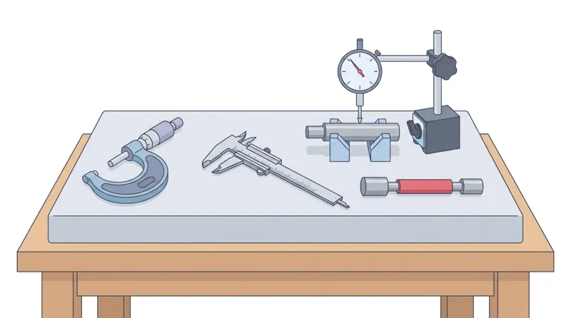
ノギス(最小読取値0.05mmなど)は1本で外径・内径・深さ・段差を測定でき、「本尺の0の手前のmm+副尺(バーニヤ)が一致した目盛」で読み取ります。
A vernier caliper (e.g., 0.05 mm resolution) measures outer diameter, inner diameter, depth, and step; read 'main scale mm before vernier zero + aligned vernier graduation'.
外側マイクロメータ(最小読取値0.01mm、ピッチ0.5mm)は「スリーブの0.5mm単位目盛+シンブルの目盛×0.01mm」で読み、ラチェットストップを回して一定の測定力で測ります。
An outside micrometer (0.01 mm resolution, 0.5 mm lead screw pitch) reads 'sleeve 0.5 mm marks + thimble division × 0.01 mm', using the ratchet stop for constant measuring force.
測定前には測定面のゴミを拭き取り、50〜75mm用マイクロメータでは50mmの基準棒を挟んでゼロ点(基点)が合っているか確認します。
Wipe measuring faces clean before use; for a 50–75 mm micrometer, verify the zero (datum) point using a 50 mm setting rod.
ダイヤルゲージはスピンドルの微小な変位を拡大表示する比較測定器で、マグネットスタンドに固定して平面度や回転軸の振れ(偏心)を測定します。
A dial gauge magnifies small spindle displacements on a circular dial and is mounted on a magnetic stand to check flatness, parallelism, or shaft runout.
Key points
- 【○正しい】マイクロメータでスリーブが「12.5mm」、シンブルが「18」の目盛を指しているときの測定値は $12.5 + 0.18 = 12.68\text{ mm}$ である。
(○ True) When a micrometer sleeve shows '12.5 mm' and the thimble aligns at '18', the reading is $12.5 + 0.18 = 12.68\text{ mm}$. - 【○正しい】マイクロメータはラチェットストップで測定力を一定にし、50〜75mm用は50mmの基準棒で基点(ゼロ点)を確認する。
(○ True) Use the ratchet stop for uniform measuring force, and check the datum of a 50–75 mm micrometer using a 50 mm setting rod. - 【×誤り】シンブルを力強く握って締め付けたり、加工直後で高温のままの工作物を精密測定するのは熱膨張誤差が出るため誤り。
(× False) Forcibly tightening the thimble by hand or precision-measuring a hot workpiece right after machining (causing thermal expansion error) is FALSE.
| Word | Meaning |
|---|---|
| ノギス | vernier caliper |
| マイクロメータ | micrometer |
| ラチェットストップ | ratchet stop |
| 基準棒 | setting rod (standard bar) |
| ダイヤルゲージ | dial gauge (dial indicator) |
限界ゲージ(栓ゲージ・ねじプラグゲージ)・ブロックゲージと三次元測定機
Limit Gauges (Plug Gauge, Thread Gauge), Gauge Blocks, and Coordinate Measuring Machines (CMM)
穴径の合否を素早く判定する「限界栓ゲージ(プラグゲージ)」や「限界ねじプラグゲージ」では、通り側(GO)が通り、止まり側(NOT GO)が通らないとき合格と判定します。
With a 'limit plug gauge' or 'limit thread plug gauge', a hole passes inspection when the GO end enters freely and the NOT GO end does not enter.
高い平面度と寸法精度を持つ「ブロックゲージ」は、測定面を清浄にして滑らせながら重ねる「リンギング(密着)」によって目的の基準寸法を作ります。
'Gauge blocks' have ultra-flat precision surfaces that are slid together under light pressure ('wringing') to build exact reference lengths.
けがきや高さ測定の基準となる平らな面には「定盤」と「ハイトゲージ」、隙間の測定には「シックネスゲージ(すきまゲージ)」、直角度の確認には「スコヤ(直角定規)」を使います。
A 'surface plate' and 'height gauge' are used for layout and height measurement, a 'feeler (thickness) gauge' measures narrow gaps, and a 'precision square' checks 90° perpendicularity.
精密測定室の標準温度はJISで「20℃」と定められており、「三次元測定機(CMM)」はプローブで座標(X・Y・Z)を測り、立体形状や形状・位置の公差を高精度に測定します。
The JIS standard reference temperature for dimensional measurement is '20°C', and a 'Coordinate Measuring Machine' (CMM) probes X-Y-Z coordinates to measure 3D geometry and geometric tolerances.
Key points
- 【○正しい】限界ゲージ(栓ゲージ・ねじゲージ)は「通り側(GO)が通り、止まり側(NOT GO)が通らない」とき合格となる。
(○ True) A limit gauge (plug or thread gauge) indicates an acceptable part when 'the GO side enters and the NOT GO side does not enter'. - 【○正しい】ブロックゲージを密着させる操作を「リンギング」といい、精密測定の標準温度は「20℃」である。
(○ True) Sliding gauge blocks together so they adhere is called 'wringing', and the standard reference temperature for precision measurement is '20°C'. - 【×誤り】通り側も止まり側も両方貫通した穴を「合格」と判定するのは誤り(穴径が大きすぎる不良)。
(× False) Judging a hole as 'acceptable' when both the GO and NOT GO ends pass completely through is FALSE (the hole is oversized).
| Word | Meaning |
|---|---|
| 限界栓ゲージ | limit plug gauge |
| ブロックゲージ | gauge block |
| リンギング | wringing |
| シックネスゲージ | feeler (thickness) gauge |
| 三次元測定機 | coordinate measuring machine (CMM) |
Drawings, Measuring and Technical Calculation
Practice this chapter in the appOfficial references
- 製造分野特定技能2号評価試験(経済産業省・JAIM) — https://www.jaim-skill.or.jp/exam/about-ssw2/
- 製造分野特定技能評価試験 試験基準(別紙) — https://www.jaim-skill.or.jp/assets/files/exam/top/exam_criteria.pdf