 Tokutei Pass
Technical Drawing and Measuring Instruments
製図・測定器
Industrial Manufacturing - Machinery and Electronics · 製造分野 · Written by Tokutei Pass based on the official study texts; not copied verbatim.
機械製図の基本(第三角法と線の種類)
Mechanical Drawing Basics (Third-Angle Projection and Line Types)
JISの機械製図で通常用いられる投影法は「第三角法」で、正面図の上に平面図、右に右側面図を配置します。
Standard JIS mechanical drawings use 'third-angle projection', placing the top view above the front view and the right side view to the right.
物体の見える外形は「太い実線(外形線)」で描き、見えない部分の形(かくれ線)は「破線」で表します。
Visible outlines of an object are drawn with 'thick continuous lines', while hidden edges are drawn with 'dashed lines'.
円の中心や対称の軸(中心線)は、「細い一点鎖線」で表します。
Center lines of circles and axes of symmetry are drawn with 'thin chain lines' (thin long-and-short dashed lines).
寸法線と寸法補助線はどちらも「細い実線」で描き、断面図の切断面に引く斜めの細い線を「ハッチング」といいます。
Dimension lines and extension lines are both drawn with 'thin continuous lines', and diagonal thin lines on cut surfaces are called 'hatching'.
Key points
- 【○正しい】JISの機械製図では「第三角法」を用い、寸法線と寸法補助線はどちらも「細い実線」で描く。
(○ True) JIS mechanical drawings use 'third-angle projection', and both dimension lines and extension lines are drawn with 'thin continuous lines'. - 【×誤り】見えない部分を「太い実線」で表したり、中心線を「太い実線」で表すのは誤り(かくれ線は破線、中心線は細い一点鎖線)。
(× False) Drawing hidden outlines or center lines with 'thick continuous lines' is FALSE (hidden lines use dashed lines; center lines use thin chain lines). - 【×誤り】断面図の切断面に引かれる斜めの細い線を「中心線」というのは誤り(正しくは「ハッチング」)。
(× False) Calling the diagonal thin lines drawn on a cross-sectional cut surface 'center lines' is FALSE (they are 'hatching').
| Word | Meaning |
|---|---|
| 第三角法 | third-angle projection |
| 外形線 | visible outline (thick continuous line) |
| 破線 | dashed line (hidden line) |
| 一点鎖線 | thin chain line (center line) |
| ハッチング | hatching (section lining) |
寸法記号(φ・R・C)と寸法公差・はめあい
Dimension Symbols (φ, R, C), Tolerances, and Fits
図面に「φ20」と書かれているときは円の直径が20mm、「R5」は半径5mmの丸みを表しています。
On a drawing, 'φ20' indicates a circle diameter of 20 mm, while 'R5' indicates a rounded corner with a radius of 5 mm.
「C2」と書かれているときは、45°の面取りで隣り合う二つの面に沿った寸法がそれぞれ2mmであることを表します。
'C2' indicates a 45-degree chamfer measuring 2 mm along each of the two adjacent surfaces.
「φ20±0.1」と書かれているとき、許容される直径の範囲は19.9mm以上、20.1mm以下です。
When 'φ20±0.1' is specified, the allowable diameter range is from 19.9 mm to 20.1 mm inclusive.
穴と軸の「はめあい」において、穴より軸の方が大きく圧入などでしっかり固定するものを「しまりばめ」といいます。
In hole-and-shaft fits, a fit where the shaft is larger than the hole so parts are firmly fixed by press-fitting is called an 'interference fit'.
Key points
- 【○正しい】「φ20」は直径20mm、「R5」は半径5mmの丸み、「C2」は45°で2mmの面取りを表す。
(○ True) 'φ20' means a 20 mm diameter, 'R5' means a 5 mm radius round, and 'C2' means a 45° chamfer of 2 mm. - 【○正しい】「φ20±0.1」の許容範囲は19.9mm以上〜20.1mm以下である。
(○ True) For 'φ20±0.1', the acceptable diameter range is 19.9 mm or more and 20.1 mm or less. - 【○正しい】穴より軸が大きく圧入などで固定するはめあいを「しまりばめ」という(すきまがあるのは「すきまばめ」)。
(○ True) A fit where the shaft is slightly larger than the hole to fix parts tightly is called an 'interference fit' (shimaribame).
| Word | Meaning |
|---|---|
| 直径 | diameter (φ) |
| 半径 | radius (R) |
| 面取り | chamfer (C) |
| 許容範囲 | allowable range (tolerance) |
| しまりばめ | interference fit |
ノギスと外側マイクロメータの測定
Measuring with Vernier Calipers and Outside Micrometers
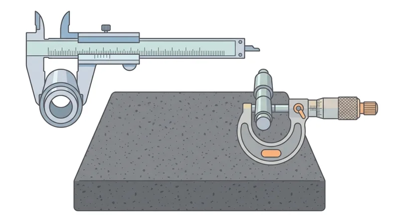
ノギスは外径・内径・深さ・段差を測定する器具で、本尺の読みと副尺(バーニヤ)の読みを足して読み取ります。
A vernier caliper measures outer diameter, inner diameter, depth, and step height by adding the main scale reading and vernier scale reading.
例えば最小読取値0.05mmのノギスで、本尺が23mm、副尺が0.35mmで合っているとき、測定値は23.35mmです。
For example, on a 0.05 mm vernier caliper, if the main scale reads 23 mm and the vernier aligns at 0.35 mm, the measurement is 23.35 mm.
最小目盛0.01mmの外側マイクロメータでは、スリーブの読み(例:7.5mm)とシンブルの読み(例:0.23mm)を足して7.73mmと読みます。
On a 0.01 mm outside micrometer, if the sleeve reads 7.5 mm and the thimble reads 0.23 mm, add both values to get 7.73 mm.
マイクロメータでラチェットストップを使う理由は、測定力を一定にして測定誤差を防ぐためです。
The ratchet stop on a micrometer is used to keep measuring force constant and prevent measurement error.
Key points
- 【×誤り】ノギスで回路の電圧・電流・電気抵抗を測定できるというのは誤り(ノギスは長さや径を測る)。
(× False) Saying a vernier caliper measures circuit voltage, current, and resistance is FALSE (it measures length, diameter, depth, and steps). - 【○正しい】本尺23mm+副尺0.35mm=23.35mm、スリーブ7.5mm+シンブル0.23mm=7.73mmと両数値を足す。
(○ True) Add both readings together: 23 mm + 0.35 mm = 23.35 mm on a caliper, and 7.5 mm + 0.23 mm = 7.73 mm on a micrometer. - 【×誤り】マイクロメータのラチェットストップは強く締め付けるためではなく、測定力を一定にするために使う。
(× False) Saying the micrometer ratchet stop is used to tighten the spindle as hard as possible is FALSE (it keeps measuring force constant).
| Word | Meaning |
|---|---|
| ノギス | vernier caliper |
| 本尺・副尺 | main scale and vernier scale |
| 外側マイクロメータ | outside micrometer |
| ラチェットストップ | ratchet stop |
| 測定力 | measuring force |
ダイヤルゲージ・ハイトゲージ・限界プラグゲージ
Dial Gauges, Height Gauges, and Limit Plug Gauges
ダイヤルゲージは、回転する軸の振れや平面の平行度などを、基準からの微小な差(変位)として読み取る測定器です。
A dial gauge (dial indicator) reads shaft runout or surface parallelism as a small displacement relative to a reference.
ハイトゲージは、精密な平らな台である定盤の上で、工作物の高さを測ったりけがき作業をしたりするときに使います。
A height gauge is used on a precision flat surface plate (jouban) to measure workpiece height or scribe layout lines.
限界プラグゲージは、穴の寸法が公差内に入っているかを調べる検査具で、通り側と止まり側があります。
A limit plug gauge inspects whether a hole diameter is within tolerance using a GO end and a NO-GO end.
限界プラグゲージで穴を検査するとき、「通り側が通り、止まり側が通らない」状態が合格です。
When inspecting a hole with a limit plug gauge, the hole passes inspection when the GO end enters and the NO-GO end does not enter.
Key points
- 【×誤り】ダイヤルゲージを部品の重さを測るために使うというのは誤り(軸の振れや平行度を測る)。
(× False) Saying a dial gauge is used to directly weigh a part is FALSE (it measures shaft runout and surface parallelism). - 【×誤り】ハイトゲージの用途を回転軸の振れ測定というのは誤り(定盤上で高さを測る)。
(× False) Saying a height gauge is held against a rotating shaft to measure runout is FALSE (it measures height on a surface plate). - 【○正しい】限界プラグゲージの検査では、「通り側が通り、止まり側が通らない」とき合格となる。
(○ True) In limit plug gauge inspection, a hole is acceptable when 'the GO end passes through and the NO-GO end does not pass'.
| Word | Meaning |
|---|---|
| ダイヤルゲージ | dial gauge (dial indicator) |
| ハイトゲージ | height gauge |
| 定盤 | surface plate |
| 限界プラグゲージ | limit plug gauge |
| 通り側・止まり側 | GO end and NO-GO end |
精密測定の標準温度(20℃)と単位換算
Standard Measurement Temperature (20°C) and Unit Conversion
金属は温度が上がると熱膨張して寸法が変わるため、JISなどの規格で定められた精密測定の標準温度は「20℃」です。
Because metals expand with heat, the standard temperature specified by JIS for precision dimensional measurement is 20°C.
加工直後で熱い工作物を測るときは、指定の測定条件に合わせ、工作物の温度が安定してから測定します。
When measuring a hot workpiece right after machining, wait until its temperature stabilizes under specified measurement conditions.
長さの単位「μm(マイクロメートル)」は1mmの1000分の1であり、1mm=1000μm(0.001mm=1μm)です。
One micrometer (μm) is one-thousandth of a millimeter: 1 mm = 1000 μm (0.001 mm = 1 μm).
したがって、0.01mmは10μm、0.05mmは50μm(5μmではない)に等しくなります。
Therefore, 0.01 mm equals 10 μm, and 0.05 mm equals 50 μm (not 5 μm).
Key points
- 【○正しい】JIS規格で定められている寸法測定の標準温度は「20℃」である。
(○ True) The standard temperature for dimensional measurement specified by JIS standards is 20°C. - 【○正しい】加工直後で熱い工作物は、すぐ測らずに温度が安定してから精密測定する。
(○ True) For a hot workpiece right after machining, allow the workpiece temperature to stabilize before taking precision measurements. - 【×誤り】長さの単位換算で「0.05mm=5μm」というのは誤り(1mm=1000μmなので、0.05mm=50μm)。
(× False) Converting 0.05 mm to '5 μm' is FALSE (since 1 mm = 1000 μm, 0.05 mm equals 50 μm).
| Word | Meaning |
|---|---|
| 標準温度 | standard temperature |
| 熱膨張 | thermal expansion |
| マイクロメートル | micrometer (μm) |
| 単位換算 | unit conversion |
Drawings and Measuring
Practice this chapter in the appOfficial references
- 製造分野特定技能1号評価試験(経済産業省・JAIM) — https://www.jaim-skill.or.jp/exam/about-ssw1/
- 製造分野特定技能評価試験 試験基準(別紙) — https://www.jaim-skill.or.jp/assets/files/exam/top/exam_criteria.pdf