
Architectural Design & Drawing (Drafting Standards, Structural Symbols, Cutting Length & Mass Calculation)
建築設計製図(製図通則・構造図記号・切り寸と質量計算)
Rebar Worker Certificate 鉄筋技能士 (Grade 1/2 theory) · 技能検定「鉄筋施工」1級・2級 学科 · Written by Tokutei Pass based on the official study texts; not copied verbatim.
建築製図通則(JIS A 0150)の尺度・方位・寸法と線の種類
Architectural Drawing Standards (JIS A 0150): Scale, North Orientation, Dimensions, and Line Types
建築製図通則(JIS A 0150)では、図面の寸法単位は原則として「ミリメートル(mm)」とし、単位記号(mm)は記入しない規則となっています。また図面に記載されている寸法数値は、縮尺にかかわらず常に「実寸(実際の仕上がり寸法)」を表します。
Under JIS A 0150 (Architectural Drawing Standards), the standard unit of dimension is the millimeter (mm) with the unit symbol omitted. Dimension numbers written on drawings always indicate the 'actual full-size dimension' regardless of the drawing scale.
例えば縮尺1/100の図面上で長さ45mmに描かれている壁の実際の長さは「45mm×100=4500mm(4.5m)」です。配置図や平面図は、特別な理由がない限り「北を図面の上」に向けて描くのが原則です。
For example, a wall drawn 45 mm long on a 1:100 scale drawing has an actual length of 45 mm × 100 = 4500 mm (4.5 m). Site plans and floor plans are oriented with 'North at the top of the sheet' in principle.
製図に用いる線の種類には、連続した「実線」、短い線を等間隔に並べた「破線」、長い線と点を交互に並べた「一点鎖線」、長い線の間に点を2つ並べた「二点鎖線」があり、太さによって太線・中線・細線を使い分けます。
Line types include solid lines (continuous), dashed lines (short equal dashes), chain lines (alternating long dash and single dot), and double-dot chain lines, combined with thick, medium, and thin line weights.
部材の切断断面の外形には「太い実線」、見える外形線には「中の実線」、寸法線・寸法補助線・引出線には「細い実線」を用い、隠れて見えない部分の形には「破線」、柱や壁の「通り芯(基準線)・中心線」には「細い一点鎖線」を用います。
Cut section outlines use thick solid lines; visible outlines use medium solid lines; dimension, extension, and leader lines use thin solid lines; hidden outlines use dashed lines; and grid reference lines (tōrishin) and centerlines use thin single-dot chain lines.
Key points
- 建築製図の寸法単位は「mm」で単位記号は省略し、平面図は原則として「北を上」にする
Dimensions are in millimeters (mm) with the unit symbol omitted, and floor plans place North at the top in principle - 見えない隠れ線には「破線」を用い、通り芯や中心線・切断線には「一点鎖線」を用いる
Hidden edges use dashed lines (hasen), while centerlines and structural grid lines use single-dot chain lines (itten sasen) - 断面外形は「太い実線」、見えがかり線は「中実線」、寸法線・引出線は「細い実線」で描く
Section outlines use thick solid lines, visible edges use medium solid lines, and dimension lines use thin solid lines
| Word | Meaning |
|---|---|
| 建築製図通則(JIS A 0150) | Architectural Drawing Standards (JIS A 0150) |
| 実線・破線・一点鎖線・二点鎖線 | solid line, dashed line, chain line, and double-dot chain line |
| 通り芯(基準線)と中心線 | structural grid line (tōrishin) and centerline |
| 寸法線・寸法補助線・引出線 | dimension line, extension line, and leader line |
設計図書の種類(配置図・平面図・立面図・断面図・構造図)
Types of Design Documents (Site Plan, Floor Plan, Elevation, Section, and Structural Drawings)
建築工事の設計図には、建物の配置・間取り・外観を示す「一般図(建築設計図)」と、骨組みの寸法や配筋を示す「構造図」、設備配管等を示す「設備図」があります。契約図書のうち文字で品質や施工法を示したものを「仕様書」といいます。
Architectural design documents consist of general architectural drawings showing layout and exterior appearance, structural drawings showing framing dimensions and reinforcement, MEP drawings, and written specifications (shiyōsho) defining material quality and workmanship.
「配置図」は敷地と道路・隣地境界線・建物位置・方位を示す図面です。「平面図」は各階の窓枠付近(床面から約1.2〜1.5mの高さ)で水平に切断して真上から見下ろした図面で、室名・壁・柱・開口部を表します。
A 'site plan (haichizu)' shows the lot boundaries, roads, and building footprint. A 'floor plan (heimenzu)' is a horizontal section cut through each story at window height (about 1.2–1.5 m above the floor) viewed from above, showing rooms, walls, columns, and openings.
「立面図」は建物の東西南北の4面の外観を真横から見た図面です。「断面図」は建物を鉛直面で切断して横から見た図面で、階高・天井高・軒高・最高高さなどを示し、その一部を大縮尺(1/20〜1/30)で詳細に描いたものを「矩計図」といいます。
An 'elevation (ritsumenzu)' shows the exterior views from north, south, east, and west. A 'section (danmenzu)' is a vertical cut through the building showing story heights, ceiling heights, and eave heights; a large-scale (1:20–1:30) detailed wall section from foundation to roof is called a 'kanabakarizu.'
「構造図」には、各階の柱・梁・床スラブの配置を上から見た「構造伏図(床伏図・基礎伏図)」、通り芯に沿った鉛直構面の骨組みを示す「軸組図」、柱・梁・スラブの鉄筋本数や径を一覧表にした「部材断面リスト」があります。
Structural drawings include 'structural framing plans (kōzō fusezu: foundation plan and floor framing plans)' viewed from above, 'framing elevations (jikugumizu)' along grid lines, and 'member section schedules (danmen list)' tabulating column, beam, and slab reinforcement.
Key points
- 「平面図」は各階を窓の高さで水平切断して上から見た図、「立面図」は建物の外観を横から見た図である
A floor plan is a horizontal cut viewed from above; an elevation shows the exterior facade from the side - 「断面図」は建物を垂直切断して階高や天井高を示す図であり、その詳細断面図を「矩計図」という
A section is a vertical cut showing story and ceiling heights; a detailed large-scale wall section is a kanabakarizu - 構造図は「構造伏図(基礎伏図・床伏図)」「軸組図」「部材断面リスト」などで構成される
Structural drawings comprise framing plans (fusezu), framing elevations (jikugumizu), and member section schedules
| Word | Meaning |
|---|---|
| 配置図・平面図・立面図・断面図 | site plan, floor plan, elevation, and section |
| 矩計図と仕様書 | detailed wall section (kanabakarizu) and written specifications |
| 構造伏図(基礎伏図・床伏図) | structural framing plan (foundation plan and floor framing plan) |
| 軸組図と部材断面リスト | framing elevation (jikugumizu) and member section schedule |
材料構造表示記号・建具表示記号と寸法記号(JIS A 0150)
Material Section Symbols, Door/Window Symbols, and Dimension Symbols (JIS A 0150)
JIS A 0150の材料断面表示記号では、「無筋コンクリート」は3本組みの斜線と点々、「鉄筋コンクリート(RC)」は3本組みの斜線の間に太い1本斜線(鉄筋を表す)を交互に入れた記号で表します。
Under JIS A 0150 material section symbols, plain concrete is shown by groups of three parallel diagonal lines with dots, whereas 'reinforced concrete (RC)' alternates groups of three thin diagonal lines with a single thick diagonal line representing reinforcement.
また「地盤(土)」は地面線の下に3本組みの斜線を互い違いの向きに連続させた記号、「割栗石・砕石」は小判形の輪を並べた記号、「砂利」は細かい丸粒を散らした記号で表します。
'Ground (soil)' is indicated below the ground line by alternating three-line diagonal hatches oriented perpendicular to adjacent groups; 'cobblestone (wariguri-ishi)' is shown as oval stones, and 'gravel' as small scattered circles.
平面図の建具記号では、1枚の扉が回転して開く軌跡(扇形や斜線)を描いた「片開き戸」、左右2枚の扉が中央から開く「両開き戸」、2枚の障子が平行にスライドする「引違い戸・引違い窓」、壁線に平行線と中央の短い直交線を描く「はめ殺し窓(FIX窓)」があります。
In floor plan door/window symbols: a single swinging leaf shows a 'single-swing door (katabirakido)'; two symmetrical swinging leaves show a 'double-swing door (ryōbirakido)'; two parallel overlapping lines with arrows show a 'double-sliding window/door (hikichigai)'; and a fixed line with a short center tick shows a 'fixed window (FIX).'
寸法補助記号では、「φ(マル・パイ)」は円形断面や丸鋼の「直径」、「D」は異形鉄筋の呼び名、「R」は曲線の「半径」、「□(カク)」は正方形の1辺寸法、「t」は板や壁・スラブの「厚さ」、「@」は鉄筋などの「配置間隔(ピッチ)」、「L」は長さを表します。
For dimension symbols: 'φ' indicates diameter, 'D' indicates deformed bar size, 'R' indicates radius, '□' indicates the side of a square section, 't' indicates plate/wall/slab thickness, '@' indicates center-to-center spacing (pitch), and 'L' indicates length.
Key points
- JIS A 0150の断面記号で、3本斜線+太線1本は「鉄筋コンクリート」、地面線下の交互3本斜線は「地盤」を表す
In JIS A 0150, alternating 3 thin lines and 1 thick diagonal line represents RC; alternating 3-line hatches below grade represent soil - 建具記号は、回転軌跡が1枚なら「片開き戸」、2枚対称なら「両開き戸」、平行2本線のスライドなら「引違い窓(戸)」である
One swinging leaf is a single-swing door, two symmetrical leaves are a double-swing door, and two parallel sliding panels are a double-sliding window - 寸法記号は、φ=直径、R=半径、□=正方形の1辺、t=厚さ、@=間隔(ピッチ)を表す
Dimension symbols: φ = diameter, R = radius, □ = square side, t = thickness, @ = spacing (pitch)
| Word | Meaning |
|---|---|
| 鉄筋コンクリートと地盤の断面表示記号 | section symbols for reinforced concrete and ground |
| 片開き戸・両開き戸・引違い窓 | single-swing door, double-swing door, and double-sliding window |
| 直径(φ)・半径(R)・正方形(□) | diameter (φ), radius (R), and square side (□) |
| 板厚(t)と鉄筋間隔(@:ピッチ) | thickness (t) and bar spacing (@: pitch) |
構造図の部材記号と基準高さ・スラブ記号の読み方
Structural Member Symbols, Level Datum Marks, and Slab Symbols
構造伏図や断面リストで用いられる部材記号(ローマ字の頭文字)は、「C」=柱(Column)、「G」=大梁(Girder)、「B」=小梁(Beam)、「S」=床スラブ(Slab)、「W」=壁(Wall)、「SW」=耐震壁(Shear Wall)、「F」=基礎(Footing)です。
Standard member symbols on structural framing plans and schedules are: 'C' = Column, 'G' = Main Girder, 'B' = Secondary Beam, 'S' = Floor Slab, 'W' = Wall, 'SW' = Shear Wall, and 'F' = Footing.
さらに複合記号として、「FG」=基礎大梁(地中梁)、「FB」=基礎小梁、「FS」=基礎スラブ(耐圧盤)、「CS」=片持ち床スラブ(Cantilever Slab)、「CG」=片持ち大梁、「CB」=片持ち小梁を表します。
Compound symbols include: 'FG' = Foundation Girder, 'FB' = Foundation Beam, 'FS' = Foundation Slab, 'CS' = Cantilever Slab, 'CG' = Cantilever Girder, and 'CB' = Cantilever Beam.
高さの基準記号では、敷地内に設ける高低測量の不動基準点を「BM(ベンチマーク)」といい、「GL」は設計地盤面、「FL」は各階の床仕上がり面、「SL」はコンクリート構造体のスラブ上面、「▽」は高さの位置を示すレベル記号です。
For elevation datums, the permanent reference point established on site for leveling is the 'BM (Benchmark)'; 'GL' is Ground Level, 'FL' is Floor Finish Level, 'SL' is Structural Slab Top Level, and '▽' is the elevation marker.
構造平面図(床伏図)のスラブ内に描かれる円形記号(スラブ記号)では、上段または左側に「スラブの厚さ(例:150=厚さ150mm)」、下段または右側に「梁天端(基準面)からのスラブ上面の下がり寸法(段差、例:-50=50mm下がり)」が記入されます。
Inside the circular slab symbol drawn on a structural floor framing plan, the two numbers indicate the 'slab thickness (e.g., 150 = 150 mm thick)' and the 'level drop (depression) of the top of the slab from the reference beam top (e.g., -50 = 50 mm drop).'
Key points
- 部材記号は、C=柱、G=大梁、B=小梁、FG=基礎梁、S=床スラブ、CS=片持ち床スラブ、F=基礎、W=壁である
Member symbols: C = column, G = main girder, B = secondary beam, FG = foundation girder, S = slab, CS = cantilever slab, F = footing, W = wall - 高さ記号は、BM=高低基準点(ベンチマーク)、GL=地盤面、FL=床仕上がり面、SL=構造体スラブ上面を表す
Level marks: BM = benchmark, GL = ground level, FL = finished floor level, SL = structural slab top level - 床伏図のスラブ記号には「スラブの厚さ」と「基準面からのスラブ天端の段差(下がり寸法)」が示される
The circular slab symbol on framing plans shows the 'slab thickness' and 'slab top level offset (drop)'
| Word | Meaning |
|---|---|
| 部材記号(C・G・B・S・W・F) | member symbols (C, G, B, S, W, F) |
| 基礎梁(FG)・基礎スラブ(FS)・片持ち床スラブ(CS) | foundation girder (FG), foundation slab (FS), and cantilever slab (CS) |
| ベンチマーク(BM)とGL・FL・SL | benchmark (BM) and GL, FL, SL |
| 床伏図のスラブ厚さと段差表示 | slab thickness and level drop notation on framing plans |
柱・梁断面リストの読み方と鉄筋施工図・加工帳
Reading Column/Beam Section Schedules, Rebar Shop Drawings, and Bar Lists
構造図の「部材断面リスト(柱リスト・梁リスト)」には、階および記号ごとに断面寸法(幅×せい)と主筋・帯筋・あばら筋・腹筋の径・本数・間隔が一覧表で示されています。
In structural 'member section schedules (column schedule and beam schedule),' cross-sectional dimensions (width × depth) and the diameter, number, and spacing of main bars, hoops, stirrups, and side-face bars are tabulated by story and member mark.
梁断面リストでは、大梁の「両端部(または左端・右端)」と「中央部」に分けて断面が描かれます。これはラーメン構造の梁では端部で上側引張、中央部で下側引張となるため、端部の上端筋本数と中央部の下端筋本数が異なるからです。また寸法「400×750」は「梁幅400mm×梁せい750mm」を表します。
In a beam section schedule, main girders are shown separately for 'end sections (left/right ends)' and 'midspan section' because rigid-frame girders have top tension at ends and bottom tension at midspan. A dimension note such as '400×750' means 'beam width 400 mm × beam depth 750 mm.'
設計構造図をもとに、鉄筋技能者が実際に鉄筋を加工・組立できるよう、継手位置・定着長さ・交差部の納まり・あき・かぶり厚さを具体的に作図した図面を「鉄筋施工図(配筋詳細図)」といいます。
Based on the structural design drawings, detailed drawings prepared for actual fabrication and placing—showing splice locations, anchorage lengths, joint detailing, clear spacing, and cover—are called 'rebar shop drawings (tekkin sekōzu).'
さらに鉄筋施工図から部材ごとに鉄筋の「形状番号・鋼種・径・各部加工寸法・1本あたりの切断長さ(切り寸)・所要本数・総質量」を拾い出して集計した帳票を「加工帳(バーリスト)」といい、加工完品の束には使用部位と寸法を記した「加工エフ(名札)」を取り付けます。
The schedule compiled from the shop drawings listing shape codes, steel grades, bar sizes, bend dimensions, cutting length per bar (kirisun), required bar counts, and total mass is called a 'bar bending schedule / bar list (kakōchō).' Each fabricated bundle is tagged with an identification tag (kakō efu).
Key points
- 梁断面リストは応力状態に応じて「端部」と「中央部」に分けて示され、「400×750」は「梁幅400mm×梁せい750mm」を意味する
Beam schedules show 'end' and 'midspan' sections separately; '400×750' means 400 mm width by 750 mm depth - 構造図をもとに納まりや継手・定着を詳細に描いた図面を「鉄筋施工図」という
Detailed drawings showing exact bar arrangement, splices, and joint details are called rebar shop drawings (tekkin sekōzu) - 鉄筋の形状・加工寸法・切り寸・本数・質量を集計した表を「加工帳(バーリスト)」といい、鉄筋束には「加工エフ」を付ける
The table summarizing bar shapes, cutting lengths, quantities, and weights is the bar list (kakōchō), and bundles carry fabrication tags (efu)
| Word | Meaning |
|---|---|
| 部材断面リスト(梁幅×梁せい) | member section schedule (beam width × beam depth) |
| 梁の端部断面と中央部断面 | beam end section and midspan section |
| 鉄筋施工図(配筋詳細図) | rebar shop drawing (placing detail drawing) |
| 加工帳(バーリスト)と加工エフ(名札) | bar bending schedule (bar list) and fabrication tag (efu) |
鉄筋の切断長さ(切り寸)とフック・曲げ伸びの計算
Calculating Rebar Cutting Length (Kirisun), Hook Allowances, and Bend Extensions
鉄筋を折り曲げると外側が伸びるため、加工後の「外寸(外側寸法)」の合計よりも実際に切断する長さ(切り寸)のほうが短くなります。この差を補正するため、技能検定や現場では外寸基準の換算式を用いて「切り寸」を計算します。
When a reinforcing bar is bent, its outer fibers stretch, making the sum of the outside dimensions (gaisun) larger than the actual straight cutting length (kirisun). Standard shop formulas convert outside dimensions into exact cutting lengths.
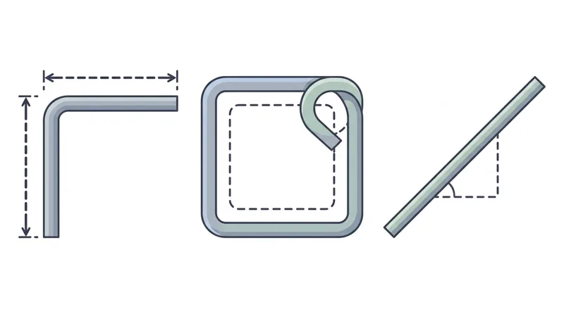
まず「途中の90°曲げ」が1箇所ある場合、外寸Aと外寸Bの和から曲げ減り「2d」を引き、「切り寸 L=A+B-2d」とします。コの字形のように途中の90°曲げが2箇所(外寸A・B・C)あれば、2d×2=4dを引いて「L=A+B+C-4d」となります。
For each intermediate 90° bend, a bend deduction of '2d' is subtracted from the sum of outside dimensions: for one 90° bend with outside legs A and B, 'Cutting length L = A + B − 2d'; for a U-bar with two 90° bends and outside dimensions A, B, and C, 'L = A + B + C − 4d.'
一方、端部の「フック1箇所あたり」に外寸へ加算する長さは、①180°フック(余長4d・内法3d)では「+5d」、②135°フック(余長6d・内法3d)では「+7d(または+6d〜8d)」、③90°フック(余長8d)では「+8d(余長12dのときは+10d)」を用います。
For each end hook, the net allowance added to the outside dimension is: (1) '+5d' for a 180° hook (4d tail, 3d inside bend diameter), (2) '+7d (or standard +6d to +8d)' for a 135° hook, and (3) '+8d (or +10d for a 12d main-bar hook)' for a 90° hook.
また高さHの「45°折り曲げ筋(ベント筋)」では、直角二等辺三角形の斜辺長が1.414H(約1.4H)となり水平投影長1.0Hより「0.4H」長くなるため、水平全長に45°折り曲げ1箇所あたり「+0.4H」(左右対称2箇所なら+0.8H)を加算して切り寸を求めます。
For a '45° bent-up (cranked) bar' of vertical offset height H, the inclined hypotenuse is 1.414H (approx. 1.4H) compared with its 1.0H horizontal projection, so '+0.4H' is added to the overall horizontal length per 45° bend (+0.8H for two symmetric bends) to obtain the cutting length.
Key points
- 外寸A・Bで途中90°曲げ1箇所の切り寸は「L=A+B-2d」、90°曲げ2箇所(外寸A・B・C)は「L=A+B+C-4d」である
Outside-dimension cutting length: one 90° bend gives 'L = A + B − 2d'; two 90° bends give 'L = A + B + C − 4d' - 180°フック(余長4d)・135°フック(余長6d)・90°フック(余長8dまたは12d)は所定の曲げ内法直径Dと余長を確保する
180° hooks (≥ 4d tail), 135° hooks (≥ 6d tail), and 90° hooks (≥ 8d or 12d tail) must satisfy the specified minimum inside bend diameter D and tail length - 高さHの45°折り曲げ加工では、斜辺長が1.4Hとなるため、水平寸法に1箇所あたり「+0.4H」の伸びを加算する
A 45° bent-up bar of height H has an inclined length of 1.4H, adding '+0.4H' per 45° bend to the horizontal length
| Word | Meaning |
|---|---|
| 切断長さ(切り寸)と外寸 | cutting length (kirisun) and outside dimension (gaisun) |
| 90°曲げの曲げ減り(1箇所につき-2d) | 90° bend deduction (−2d per bend) |
| 閉鎖型帯筋の切り寸(4A+8d) | cutting length of closed square hoop (4A + 8d) |
| 45°折り曲げ筋の伸び(1箇所につき+0.4H) | extension of 45° bent-up bar (+0.4H per bend) |
鉄筋の所要本数の割付け計算と総質量の積算
Calculating Required Number of Bars by Pitch and Total Rebar Mass
床スラブや壁、柱の帯筋、梁のあばら筋のように、一定の配置区間長さLの中に間隔(ピッチ)Pで鉄筋を並べる場合、区間の始端と終端の両方に鉄筋を配置するため、所要本数Nは「間隔数+1本」となります。
When distributing slab bars, wall bars, column hoops, or beam stirrups at a center-to-center pitch P over a placing length L, a bar is placed at both the starting end and the finishing end, so the required number of bars N equals the number of spaces plus 1.
すなわち「所要本数 N=(配置区間長さL ÷ ピッチP)+ 1」で計算し、L÷Pが割り切れず端数が出た場合は、指定ピッチ以下を守るため端数を「切り上げ」てから1を足します。例えば長さ4000mmの区間に@200(200mmピッチ)で配筋するときは、(4000÷200)+1=20+1=「21本」が必要です。
Thus the formula is 'Required bars N = (Placing length L ÷ Pitch P) + 1.' If L ÷ P is not a whole number, round the quotient UP to the next integer before adding 1. For example, placing bars at @200 (200 mm pitch) over a 4000 mm length requires (4000 ÷ 200) + 1 = 20 + 1 = '21 bars.'
もし長さ3500mmの区間に@200で配筋する場合は、3500÷200=17.5となるため切り上げて18間隔とし、18+1=「19本」となります。うっかり「+1」を忘れて20本や18本としてしまうミスが試験で最も多いため注意します。
If bars are placed at @200 over a 3500 mm length, 3500 ÷ 200 = 17.5, which rounds up to 18 spaces, giving 18 + 1 = '19 bars.' Forgetting to add the '+1' starter bar is the most common exam mistake.
また鉄筋の「総質量(kgまたはt)」は、「1本あたりの切り寸(m)× 所要本数(本)× 単位質量(kg/m)」で求めます。例えば切り寸5.0mのD16(単位質量1.56kg/m)が40本あるとき、総全長は5.0m×40本=200mとなり、総質量は200m×1.56kg/m=「312kg(0.312t)」となります。
Total rebar mass (kg or t) is calculated as 'Cutting length per bar (m) × Number of bars × Unit mass (kg/m).' For example, 40 bars of D16 (unit mass 1.56 kg/m) each 5.0 m long have a total length of 5.0 × 40 = 200 m and a total mass of 200 × 1.56 = '312 kg (0.312 t).'
Key points
- 配置長さLにピッチPで並べる鉄筋本数は「N=(L÷P)+1」で求め、L÷Pに端数が出たときは切り上げてから1を足す
Number of bars over length L at pitch P is 'N = (L ÷ P) + 1'; round any fraction in L ÷ P up before adding 1 - 長さ4000mmに@200で配筋するときの所要本数は、4000÷200+1=「21本」である(20本ではない)
Placing bars at @200 over 4000 mm requires 4000 ÷ 200 + 1 = 21 bars (not 20 bars) - 鉄筋の総質量(kg)=「1本の長さ(m)× 本数 × 1mあたりの単位質量(kg/m)」で計算する
Total rebar mass (kg) = Length per bar (m) × Number of bars × Unit mass (kg/m)
| Word | Meaning |
|---|---|
| 所要本数の計算式(配置長さ÷ピッチ+1) | bar count formula (placing length ÷ pitch + 1) |
| 端数の切り上げ処理 | rounding up fractional spaces |
| 鉄筋総全長(切り寸×本数) | total bar length (cutting length × number of bars) |
| 鉄筋総質量(総全長×単位質量) | total rebar mass (total length × unit mass) |
主筋・帯筋の外寸算出と実技的読図計算の応用
Calculating Outside Hoop/Stirrup Dimensions and Practical Drawing Takeoff Calculations
構造図のコンクリート断面寸法から帯筋やあばら筋の「加工外寸」を求めるときは、コンクリートの外形寸法から「両側のかぶり厚さ(2箇所分)」を引きます。かぶり厚さは最外縁である帯筋・あばら筋の外側表面までの距離だからです。
To find the 'outside fabrication dimension (kakō gaisun)' of a column hoop or beam stirrup from the concrete section dimensions on a structural drawing, subtract 'twice the concrete cover (both sides)' from the concrete dimension, because cover is measured to the outer surface of the hoop or stirrup.
例えば、断面寸法が600mm×600mmの正方形柱で、帯筋の外側のかぶり厚さが上下左右とも40mmのとき、帯筋の加工外寸Aは「600-40×2=520mm」となります(片側だけ引いて560mmとしないよう注意します)。
For example, in a 600 mm × 600 mm square column with a 40 mm concrete cover to the outside of the hoop on all four sides, the outside hoop dimension A is '600 − 40 × 2 = 520 mm' (be careful not to subtract cover on only one side).
同様に、梁幅400mm×梁せい700mmの大梁で、側面および下端の設計かぶり厚さが40mmのとき、あばら筋の横幅外寸は「400-40×2=320mm」、縦外寸は「700-40×2=620mm」となります。
Similarly, for a main girder 400 mm wide by 700 mm deep with 40 mm design cover, the stirrup outside width is '400 − 40 × 2 = 320 mm' and outside height is '700 − 40 × 2 = 620 mm.'
また両端の柱中心間距離(スパン)が6000mm、柱断面が600mm×600mmのとき、柱面間の「内法スパンL0」は「6000-300-300=5400mm」となります。このように構造図の通り芯寸法から柱や梁の片側寸法を差し引いて内法寸法を求め、定着長さやフック余長を加えて主筋の切り寸を求めます。
When the center-to-center column span is 6000 mm and the columns are 600 mm × 600 mm centered on the grid lines, the 'clear span L0 between column faces' is '6000 − 300 − 300 = 5400 mm.' Adding the required anchorage lengths at both ends to L0 yields the main bar cutting length.
Key points
- 帯筋・あばら筋の「加工外寸」は、「コンクリート断面寸法-両側のかぶり厚さ(×2)」で求める
Outside dimension of a hoop or stirrup = Concrete section dimension − 2 × Concrete cover - 断面600mm×600mmの柱でかぶり厚さ40mmのとき、帯筋外寸は600-80=520mm、梁400mm×700mmでかぶり40mmならあばら筋外寸は320mm×620mmとなる
For a 600×600 mm column with 40 mm cover, hoop outside size is 520×520 mm; for a 400×700 mm beam with 40 mm cover, stirrup outside size is 320×620 mm - 柱面間の「内法スパンL0」は、「柱芯間距離(スパン)-左右の柱心から柱面までの寸法」で求める
Clear span between column faces L0 = Center-to-center span − Column half-depths at both ends
| Word | Meaning |
|---|---|
| 帯筋・あばら筋の加工外寸(断面寸法-2×かぶり) | outside hoop/stirrup dimension (section size − 2 × cover) |
| 柱中心間距離(スパン)と内法スパン(L0) | center-to-center span and clear span (L0) |
| 柱心(通り芯)と柱面 | column centerline (grid line) and column face |
| 主筋の切り寸算出(内法+両端定着長さ) | main bar cutting length calculation (clear span + end anchorages) |
Architectural & Shop Drawings
Practice this chapter in the appOfficial references
- 日本産業規格 JIS A 0150 建築製図通則(日本産業標準調査会 JISC) — https://www.jisc.go.jp/
- 鉄筋施工技能検定 試験科目及びその範囲並びにその細目(厚生労働省) — https://www.mhlw.go.jp/stf/seisakunitsuite/bunya/koyou_roudou/jinzaikaihatsu/ability_skill/ginoukentei/index.html