
Fault Diagnosis, Measurement, and Completion Inspection (Practical)
故障診断・測定・完成検査(実技)
Automobile Maintenance (SSW 2) · 自動車整備分野(2号) · Written by Tokutei Pass based on the official study texts; not copied verbatim.
サーキット・テスタの読み取り方とランプ回路の電圧降下診断(実技・第1課題)
How to Read a Circuit Tester and Lamp Circuit Voltage Drop Diagnosis (Practical Task 1)
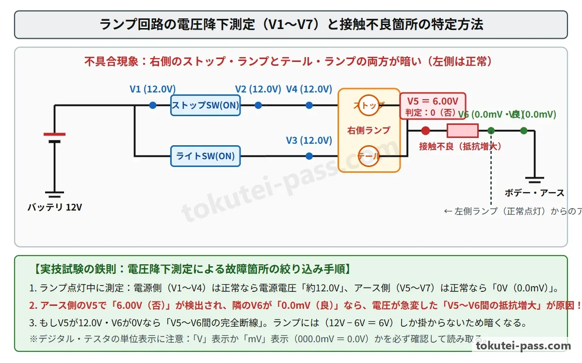
2号実技試験の第1課題で出題される「ランプ回路の電圧降下診断」では、スイッチをONにして回路に電流を流した状態(負荷状態)で、デジタル式サーキット・テスタの黒リード棒を「バッテリのマイナス端子(アース)」に固定し、赤リード棒を各測定点(V1〜V7)に当てて電圧を読み取る。
In 'Lamp Circuit Voltage Drop Diagnosis' appearing in Task 1 of the Type 2 practical exam, with the switch turned ON so current flows through the circuit (under load), fix the black lead of the digital circuit tester to the 'negative (−) battery terminal (ground)' and touch the red lead to each measurement point (V1 to V7) to read the voltage.
【デジタル式サーキット・テスタの読み取り方】①ロータリ・スイッチが直流電圧「V」レンジにあることを確認する。②液晶画面の「数値」だけでなく、右端に表示されている単位が「V(ボルト)」か「mV(ミリボルト:1,000mV=1V)」かを必ず確認する(例:「0.0mV」は「0V」を意味する)。
【How to Read a Digital Circuit Tester】 (1) Verify that the rotary selector is set to the DC voltage 'V' range. (2) Always check not only the numerical value on the LCD screen, but also whether the unit displayed at the right edge is 'V (volts)' or 'mV (millivolts: 1,000 mV = 1 V)' (for example, '0.0 mV' means '0 V').
正常な12Vランプ回路(スイッチON時)では、電源からランプ手前までの測定点(V1〜V4)はすべて「約12.00V」を示し、ランプで12Vすべてが消費(電圧降下)されるため、ランプ下流のアース側測定点(V5〜V7)はすべて「約0V(0.0mV)」を示す。
In a normal 12 V lamp circuit (when the switch is ON), all measurement points from the power supply up to just before the lamp (V1 to V4) read 'approx. 12.00 V', and because all 12 V is consumed (dropped) across the lamp, the downstream ground-side points after the lamp (V5 to V7) all read 'approx. 0 V (0.0 mV)'.
もし「ランプが暗い」という故障時に、ランプ手前のV1〜V4がすべて「12.00V(良)」であるにもかかわらず、ランプ直後(アース側)の「V5が6.00V(否)」を示し、その次の「V6およびV7が0.0mV(良)」を示したとしよう。
Suppose during a fault where 'the lamp is dim', V1 to V4 before the lamp all read '12.00 V (Good / 良)', but immediately after the lamp on the ground side, 'V5 reads 6.00 V (NG / 否)', while the next points 'V6 and V7 read 0.0 mV (Good / 良)'.
この測定結果は、本来0VであるはずのV5に6.00Vが残っており、V5(6.00V)とV6(0V)の間で6.00Vもの異常な電圧降下が起きていることを意味するため、不具合箇所は「V5とV6の間(コネクタまたはハーネスの接触不良・過大な接触抵抗)」であると特定できる。
This measurement result means 6.00 V remains at V5 (which should be 0 V) and an abnormal voltage drop of 6.00 V is occurring between V5 (6.00 V) and V6 (0 V); thus, the faulty location can be pinpointed as 'between V5 and V6 (poor contact / excessive contact resistance in the connector or harness)'.
Key points
- サーキット・テスタ読み取り時は、画面右端の単位「V」と「mV(0.0mV=0V)」の違いを必ず確認する。
When reading a digital circuit tester, always verify the difference between the units 'V' and 'mV (0.0 mV = 0 V)' at the right edge of the display. - スイッチON時の正常値は、ランプより電源側(V1〜V4)が「約12V」、ランプよりアース側(V5〜V7)が「約0V(0.0mV)」である。
Normal values with the switch ON are 'approx. 12 V' on the power supply side before the lamp (V1–V4) and 'approx. 0 V (0.0 mV)' on the ground side after the lamp (V5–V7). - アース側のV5で「6.00V(否)」、V6で「0.0mV(良)」のとき、異常な接触抵抗がある不具合箇所は「V5とV6の間」である。
When V5 on the ground side reads '6.00 V (NG)' and V6 reads '0.0 mV (Good)', the faulty section with abnormal contact resistance is 'between V5 and V6'. - 【例】ランプ上流V4が12.00V、ランプ下流V5が6.00V、V6が0.0mV(0V)のとき → ランプにかかっている電圧 = 12.00 − 6.00 = 6.00V、V5〜V6間の異常電圧降下 = 6.00 − 0 = 6.00V
Example: When V4 upstream of the lamp is 12.00V, V5 downstream is 6.00V, and V6 is 0.0mV (0V) → Voltage applied to the lamp = 12.00 − 6.00 = 6.00V; abnormal voltage drop between V5 and V6 = 6.00 − 0 = 6.00V
| Word | Meaning |
|---|---|
| サーキット・テスタ(VレンジとmV表示) | circuit tester (V range and mV display) |
| 電圧降下(ボルテージ・ドロップ) | voltage drop |
| 接触不良と接触抵抗 | poor contact and contact resistance |
| 良否判定(良・否) | pass/fail judgment (Good 良 / NG 否) |
サーキット・テスタによる抵抗・導通・電流の測定手順
Resistance, Continuity, and Current Measurement Procedures Using a Circuit Tester
サーキット・テスタで部品や配線の「抵抗(Ω)」や「導通」を測定する際は、テスタ内部の電池から測定電流を流して測定するため、対象回路に車両のバッテリ電圧がかかっていると正確に測定できず、テスタを破損するおそれがある。
When measuring component or wiring 'resistance (Ω)' or 'continuity' with a circuit tester, the tester sends a measuring current from its internal battery; if vehicle battery voltage is present on the target circuit, accurate measurement is impossible and the tester may be damaged.
そのため抵抗・導通を測定する前には、「必ず回路のスイッチをOFFにする(またはバッテリのマイナス端子や測定対象部品のコネクタを外す)」ことが絶対のルールである。
Therefore, before measuring resistance or continuity, it is an absolute rule to 'always turn the circuit switch OFF (or disconnect the negative battery terminal or unplug the connector of the target component)'.
また指針が振れる「アナログ式サーキット・テスタ」で抵抗を測定する際は、測定前および測定レンジ(×1、×10、×1kなど)を切り替えるたびに、赤と黒のテスト・リード先端を接触(ショート)させ、「0Ω調整つまみ」を回して指針を右端の「0Ω」に合わせる(0点調整)。
Additionally, when measuring resistance with an 'analog (pointer) circuit tester', before measurement and every time you switch the resistance range (×1, ×10, ×1k, etc.), touch (short) the tips of the red and black test leads together and turn the '0Ω adjustment knob' to align the pointer with '0Ω' at the right end (zero adjustment).
回路に流れる「電流(A)」をサーキット・テスタで測定する際は、テスタを回路に対して「直列」に接続する(誤って電源に並列につなぐと大電流が流れてテスタ内のヒューズが切れる)。
When measuring 'current (A)' flowing in a circuit with a circuit tester, connect the tester in 'series' with the circuit (accidentally connecting it in parallel across the power supply will cause a large current to blow the tester's internal fuse).
なお、スタータ電流やオルタネータ発電電流などの大電流や暗電流を配線を切り離さずに測定する際には、配線の周囲に生じる磁界を検出する「クランプ・メータ(電流プローブ)」を用いる。
Note that when measuring large currents—such as starter current or alternator output current—or dark current without disconnecting wiring, a 'clamp meter (current probe)' that detects the magnetic field around the wire is used.
Key points
- 抵抗(Ω)・導通を測定する際は、必ず回路の電源を「OFF」にし、コネクタを取り外して単体で測定する。
When measuring resistance (Ω) or continuity, always turn circuit power 'OFF' and unplug the connector to measure the isolated part. - アナログ式テスタで抵抗レンジを変えたときは、赤・黒リード棒を接触させて必ず「0Ω調整」を行う。
Whenever changing the resistance range on an analog tester, short the red and black leads together and perform '0Ω adjustment'. - 電圧計は回路に「並列」に、電流計は回路に「直列」に接続して測定する。
Connect a voltmeter in 'parallel' with the circuit, and connect an ammeter in 'series' with the circuit.
| Word | Meaning |
|---|---|
| 抵抗測定(Ωレンジ)と導通点検 | resistance measurement (Ω range) and continuity check |
| 0Ω(ゼロオーム)調整 | 0Ω (zero-ohm) adjustment |
| 並列接続(電圧)と直列接続(電流) | parallel connection (voltage) and series connection (current) |
| クランプ・メータと暗電流 | clamp meter and dark current |
コンプレッション・ゲージの読み取り方と圧縮圧力測定(実技・第2課題)
How to Read a Compression Gauge and Compression Pressure Measurement (Practical Task 2)
2号実技試験の第2課題などで出題される「コンプレッション・ゲージを用いた圧縮圧力測定」では、正確かつ安全に測定するための「4つの事前準備・測定条件」が最頻出である。
In 'Compression Pressure Measurement Using a Compression Gauge' (Task 2 of the Type 2 practical exam), the 'four preparation and measurement conditions' for accurate and safe testing appear most frequently.
【圧縮圧力測定の4条件】①エンジンを十分に「暖機(水温80〜90℃)」する。②インジェクタのコネクタ等を外して「燃料噴射を停止」する。③「すべての気筒のスパーク・プラグを取り外す」。④アクセルを踏み込んで「スロットル・バルブを全開」にし、スタータで回して最大値を読む。
【4 Conditions for Compression Measurement】 (1) Thoroughly 'warm up the engine (coolant temp 80–90℃)' and verify the battery is fully charged. (2) Unplug injector connectors, etc. to 'stop fuel injection' during cranking and disable ignition. (3) 'Remove the spark plugs from ALL cylinders' to reduce cranking resistance. (4) Depress the accelerator pedal fully to 'open the throttle valve all the way', crank the engine with the starter at specified RPM, and read the maximum pointer deflection.
【コンプレッション・ゲージの読み取り方と判定手順】①文字盤の単位(MPa)と最小1目盛りの値(例:0.1MPaの間が5分割なら1目盛り=0.02MPa、2分割なら0.05MPa)を確認して指針を読む。②各気筒の測定値を「限度値(例:1.05MPa)」と比較し、限度値未満の気筒は「否」と判定する。
【How to Read a Compression Gauge & Judgment Procedure】 (1) Check the dial unit (MPa) and the value of 1 smallest division (e.g., if 0.1 MPa is divided into 5 parts, 1 division = 0.02 MPa; if into 2 parts, 0.05 MPa) and read the pointer. (2) Compare each cylinder's reading against the 'limit value (e.g., 1.05 MPa)'; any cylinder below the limit is judged 'NG (否)'.
さらに、③全気筒の測定値のうち「最高値 − 最低値」を計算して「各気筒間の差(気筒間差)」を求め、その差が基準(例:0.10MPa以内)を超えていれば気筒間差も「否」となる。
Furthermore, (3) calculate 'Highest reading − Lowest reading' among all cylinders to find the 'inter-cylinder difference'; if that difference exceeds the standard (e.g., within 0.10 MPa), the inter-cylinder difference is also judged 'NG (否)'.
なお、圧縮圧力が低い気筒のプラグ・ホールからエンジン・オイルを少量注入して再測定した際、圧力が大きく上昇すれば「ピストン・リングまたはシリンダ壁の摩耗」、ほとんど変化しなければ「バルブの密着不良またはヘッド・ガスケット抜け」と診断できる。
Note that if a small amount of engine oil is poured through the spark plug hole of a low-compression cylinder and re-measured, a large rise in pressure diagnoses 'piston ring or cylinder wall wear', whereas little to no change diagnoses 'poor valve seating or a blown head gasket'.
Key points
- 圧縮圧力測定の4条件:①暖機後、②燃料噴射を停止、③「全気筒」のスパーク・プラグを取り外す、④スロットル・バルブを「全開」にしてクランキングする。
4 compression measurement conditions: (1) After warm-up, (2) Stop fuel injection, (3) Remove spark plugs from 'ALL cylinders', (4) Crank with the throttle valve 'fully open'. - 気筒間差 =「最高気筒の圧縮圧力 − 最低気筒の圧縮圧力」で求め、限度値と比較する。
Inter-cylinder difference = 'Highest cylinder compression − Lowest cylinder compression', compared against the limit value. - プラグ穴からオイルを入れて圧力が上がれば「リング・シリンダ摩耗」、変わらなければ「バルブ密着不良・ガスケット抜け」である。
If adding oil through the plug hole raises pressure, it indicates 'ring/cylinder wear'; if unchanged, it indicates 'poor valve contact or head gasket leak'. - 【例】第1気筒1.30MPa、第2気筒0.85MPa、第3気筒1.25MPa、第4気筒1.30MPa(限度1.05MPa、気筒間差0.10MPa以内) → 第2気筒は0.85MPaで「否」、最大気筒間差 = 1.30 − 0.85 = 0.45MPa(否)
Example: Cyl #1 = 1.30MPa, Cyl #2 = 0.85MPa, Cyl #3 = 1.25MPa, Cyl #4 = 1.30MPa (limit 1.05MPa, difference ≤ 0.10MPa) → Cyl #2 is 'NG (否)' at 0.85MPa, max inter-cylinder difference = 1.30 − 0.85 = 0.45MPa ('NG / 否')
| Word | Meaning |
|---|---|
| コンプレッション・ゲージ(圧縮圧力計) | compression gauge |
| スロットル・バルブ全開と燃料噴射停止 | throttle valve fully open and fuel injection stop |
| 気筒間差(最高値 − 最低値) | inter-cylinder difference (highest − lowest) |
| バルブ密着不良とピストン・リング摩耗 | poor valve contact and piston ring wear |
ダイヤル・ゲージの読み取り方とシャフトの振れ・曲がり測定(実技・第3課題)
How to Read a Dial Gauge and Shaft Runout / Bend Measurement (Practical Task 3)
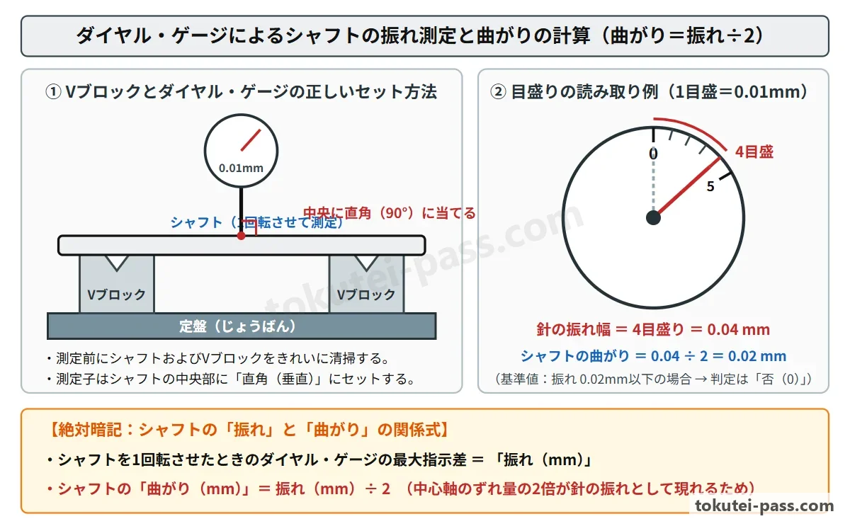
2号実技試験の第3課題などで出題される「ダイヤル・ゲージを用いたシャフトの曲がり測定」では、まず事前準備として「シャフトおよびVブロックの汚れ・油分をきれいに清掃」し、定盤の上に置いた左右のVブロックでシャフトの両端ジャーナル部を支持する。
In 'Shaft Bend Measurement Using a Dial Gauge' (Task 3 of the Type 2 practical exam), first as preparation, 'thoroughly clean dirt and oil from the shaft and V-blocks', and support both end journals of the shaft on left and right V-blocks placed on a surface plate.
次にマグネット・スタンドでダイヤル・ゲージを固定し、スピンドル(測定子)を「シャフトの中央部に対して直角(90°)」に当て、スピンドルが上下どちらにも動けるようあらかじめ少し押し込んでから、外枠ベゼルを回して長針を「0」に合わせる。
Next, secure the dial gauge with a magnetic stand, place the spindle (measuring contact point) 'perpendicular (90°) to the center of the shaft', pre-depress the spindle slightly so it can move both up and down, and rotate the outer bezel to set the long pointer to '0'.
【ダイヤル・ゲージの読み取り方】①内側の「短針」で「1mm単位」を読む。②外周の「長針(1周100目盛り=1.00mm)」で「0.01mm単位」を読む。③シャフトを手でゆっくり1回転させたときの長針の最大目盛りと最小目盛りの差(振れ幅)が「振れ」である。
【How to Read a Dial Gauge (0.01 mm minimum graduation)】 (1) Read '1 mm increments' on the small inner 'short pointer'. (2) Read '0.01 mm increments (1 division = 0.01 mm, 1 full turn of 100 divisions = 1.00 mm)' on the large outer 'long pointer'. (3) Slowly rotate the shaft 1 full revolution by hand; the difference between the maximum and minimum readings of the long pointer (total swing) is the 'runout (振れ)'.
ここで最も重要な計算ルールは、シャフトを1回転させると曲がりの山(+側)と谷(−側)の両方が測定されるため、シャフトの「曲がり(Bend)」はダイヤル・ゲージが示した「振れの半分(曲がり = 振れ ÷ 2)」になることである。
The single most important calculation rule here is that rotating the shaft one full turn measures both the high peak (+ side) and low valley (− side) of the bend, so the shaft 'bend (曲がり)' is 'half of the dial gauge runout (Bend = Runout ÷ 2)'.
したがって、ダイヤル・ゲージから読み取った「振れ」をそのまま限度値と比べるのではなく、必ず2で割って「曲がり」を算出してから「曲がり限度」と比較し、良・否を判定する(ディスク・ロータの振れやフライホイールの面振れはそのまま「振れ」として読む点と区別する)。
Therefore, do not directly compare the 'runout' read from the dial gauge against the limit value; always divide by 2 to calculate the 'bend' first, and then compare it with the 'bend limit' to judge Good (良) or NG (否) (distinguish this from disc rotor runout or flywheel face runout, which are read directly as runout).
Key points
- 測定前にシャフトとVブロックを清掃し、ダイヤル・ゲージの測定子は被測定物に「直角(90°)」に当てる。
Clean the shaft and V-blocks before measurement, and set the dial gauge spindle 'perpendicular (90°)' to the object being measured. - 最小目盛り0.01mmのダイヤル・ゲージは、短針が「1mm単位」、長針が「0.01mm単位(1周=1.00mm)」を示す。
On a dial gauge with 0.01 mm minimum graduations, the short pointer indicates '1 mm units' and the long pointer indicates '0.01 mm units (1 turn = 1.00 mm)'. - シャフトの「曲がり = ダイヤル・ゲージの振れ ÷ 2」であり、2で割った値を曲がり限度と比較して良否を判定する。
Shaft 'Bend = Dial gauge runout ÷ 2'; compare the halved value against the bend limit to judge pass or fail. - 【例】シャフトを1回転させたときのダイヤル・ゲージの長針が「0」から「8(0.08mm)」まで動き、曲がり限度が0.03mmのとき → 振れ = 0.08mm、シャフトの曲がり = 0.08 ÷ 2 = 0.04mm(限度0.03mmを超えるため「否」)
Example: When rotating a shaft 1 turn moves the dial gauge long pointer from '0' to '8 (0.08mm)' and the bend limit is 0.03mm → Runout = 0.08mm; Shaft bend = 0.08 ÷ 2 = 0.04mm (exceeds the 0.03mm limit, so judged 'NG / 否') - 【例】長針が0を挟んで左に2目盛り(−0.02mm)、右に4目盛り(+0.04mm)振れたとき → 振れ = 0.02 + 0.04 = 0.06mm、シャフトの曲がり = 0.06 ÷ 2 = 0.03mm
Example: When the long pointer swings 2 divisions left (−0.02mm) and 4 divisions right (+0.04mm) across 0 → Runout = 0.02 + 0.04 = 0.06mm; Shaft bend = 0.06 ÷ 2 = 0.03mm
| Word | Meaning |
|---|---|
| ダイヤル・ゲージ(長針0.01mm・短針1mm) | dial gauge (long pointer 0.01 mm, short pointer 1 mm) |
| マグネット・スタンドとVブロック・定盤 | magnetic stand, V-blocks, and surface plate |
| シャフトの振れと曲がり(曲がり=振れ÷2) | shaft runout and bend (Bend = Runout ÷ 2) |
| 測定子の直角(90°)当てと0点セット | perpendicular (90°) contact and zero setting |
ノギス・マイクロメータ・シリンダ・ゲージ・プラスチゲージの読み取り方
How to Read a Vernier Caliper, Micrometer, Cylinder Gauge, and Plastigage
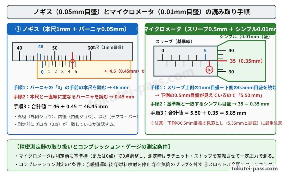
【ノギス(最小読み取り値0.05mm)の読み取り方】①副尺(バーニヤ)の「0」線のすぐ左側(手前)にある「本尺の目盛り」を「1mm単位」で読む。②本尺の目盛り線と「一直線に一致している副尺の目盛り」を探して「0.05mm単位」で読む。③「本尺の値 + 副尺の値」を足す。
【How to Read a Vernier Caliper (0.05 mm minimum reading)】 (1) First, read the 'main scale graduation' immediately to the left of (before) the position pointed to by the '0' graduation line of the vernier scale in '1 mm increments'. (2) Next, find where a graduation line on the vernier scale 'aligns in a single straight line' with a graduation line on the main scale, and read the vernier number in '0.05 mm increments'. (3) Finally, add 'Main scale value + Vernier scale value'.
【外側マイクロメータ(0.01mm)の読み取り方】基準棒で0点調整を行い、ラチェット・ストップで一定圧で挟む。①「スリーブ上側目盛り」で「1mm単位」を読む。②最大の注意点として、「スリーブ下側の0.5mm目盛り線」が見えていれば「0.50mm」を加える。
【How to Read an Outside Micrometer (0.01 mm minimum reading)】 Before measuring, adjust the zero point using a standard bar, and during measurement turn the ratchet stop until it clicks to apply constant pressure. (1) Read the '1 mm increments' visible to the left of the thimble edge on the 'upper sleeve scale'. (2) As the most important check, see whether a '0.5 mm graduation line on the lower sleeve scale' is visible! If visible, add '0.50 mm'; if not visible, add '0.00 mm'.
③続いて、スリーブ基線(横線)と一致している「シンブル周上目盛り(1目盛り=0.01mm、1周50目盛り=0.50mm)」を読む。④最後に「スリーブ上側(1mm)+ スリーブ下側(0.50mmの有無)+ シンブル(0.01mm)」を合計する。
(3) Next, read the 'thimble circumferential scale (1 division = 0.01 mm, 1 turn of 50 divisions = 0.50 mm)' that aligns with the sleeve baseline (horizontal line). (4) Finally, sum 'Upper sleeve (1 mm) + Lower sleeve (0.50 mm if visible) + Thimble (0.01 mm)'.
また「シリンダ・ゲージ」はシリンダ内径を測定する工具であり、上下方向(上部・中央部・下部)の内径差を「テーパ摩耗」、ピストン・ピン方向(軸方向)とスラスト方向(直角方向)の内径差を「オーバル(楕円)摩耗」という。
Additionally, a 'cylinder gauge' measures cylinder bore diameter: the diameter difference along the vertical axis (top, middle, bottom) is called 'taper wear', and the diameter difference between the piston pin axis direction and the thrust (perpendicular) direction is called 'oval (out-of-round) wear'.
クランクシャフトの「オイル・クリアランス(油すき間)」を測定する「プラスチゲージ」は、ジャーナルに糸状のゲージを置いてベアリング・キャップを規定トルクで締め付け(このときシャフトは絶対に回さない)、再び外して潰れたゲージの「最も幅の広い部分」を定規と照らし合わせて読み取る(潰れた幅が広いほどクリアランスは小さい)。
'Plastigage' for measuring crankshaft 'oil clearance' is used by placing a thread-like plastic gauge on the journal, tightening the bearing cap to specified torque (never rotate the shaft at this time), removing the cap again, and matching the 'widest part' of the crushed gauge against the paper scale (the wider the crushed strip, the smaller the oil clearance).
Key points
- ノギスの測定値 =「副尺の0線手前の本尺目盛り(1mm単位)+ 本尺と一直線に一致した副尺目盛り(0.05mm単位)」。
Vernier caliper reading = 'Main scale graduation before the vernier 0 line (1 mm units) + Vernier graduation aligned with a main scale line (0.05 mm units)'. - マイクロメータの測定値 =「スリーブ上側(1mm)+ スリーブ下側(0.50mmが見えるか必ず確認!)+ シンブル目盛り(0.01mm)」。
Micrometer reading = 'Upper sleeve (1 mm) + Lower sleeve (always check if 0.50 mm is visible!) + Thimble graduation (0.01 mm)'. - プラスチゲージは潰れた「最も幅の広い部分」を読み、幅が広いほどオイル・クリアランスは「小さい」(測定中はシャフト回転厳禁)。
Read Plastigage at its 'widest crushed part'; a wider strip means a 'smaller' oil clearance (rotating the shaft during measurement is strictly prohibited). - 【例】ノギスの副尺「0」が本尺24mmと25mmの間にあり、副尺の「3.5(0.35mm)」の線が本尺と一致しているとき → 24.00 + 0.35 = 24.35mm
Example: When the vernier '0' of a caliper lies between 24mm and 25mm on the main scale and the vernier '3.5 (0.35mm)' line aligns with the main scale → 24.00 + 0.35 = 24.35mm - 【例】0〜25mmマイクロメータでスリーブ上側が「6mm」、下側の「0.5mm線」が見えており、シンブルが「28(0.28mm)」を示すとき → 6.00 + 0.50 + 0.28 = 6.78mm
Example: On a 0–25mm micrometer, when the upper sleeve shows '6mm', the lower '0.5mm line' is visible, and the thimble indicates '28 (0.28mm)' → 6.00 + 0.50 + 0.28 = 6.78mm
| Word | Meaning |
|---|---|
| ノギス(本尺と副尺・0.05mm) | vernier caliper (main scale and vernier scale / 0.05 mm) |
| マイクロメータ(スリーブ0.5mm目盛りとシンブル0.01mm) | micrometer (sleeve 0.5 mm scale and thimble 0.01 mm) |
| シリンダ・ゲージ(テーパ摩耗とオーバル摩耗) | cylinder gauge (taper wear and oval wear) |
| プラスチゲージ(オイル・クリアランス測定) | Plastigage (oil clearance measurement) |
故障診断の基本手順と完成検査機器(排ガス・前照灯・制動力)
Basic Troubleshooting Workflow and Completion Inspection Testers (Exhaust, Headlights, Brakes)
自動車の故障診断(トラブルシューティング)を効率よく行う基本手順は、①「問診と現象の確認(いつ・どのような条件で発生するか)」、②「外部診断器によるDTC・フリーズ・フレーム・データの読み取りと基本点検」、③「故障原因の絞り込みと単体測定」、④「修理・部品交換」、⑤「DTC消去と修理後の確認テスト」である。
The basic workflow for efficient automotive troubleshooting consists of five steps: (1) 'Customer interview and symptom confirmation (when and under what conditions it occurs)', (2) 'Reading DTCs and Freeze Frame Data with an external scan tool plus basic inspection', (3) 'Narrowing down causes and component testing', (4) 'Repair and part replacement', and (5) 'Clearing DTCs and post-repair verification testing'.
完成検査で用いる「CO・HCテスタ(一酸化炭素・炭化水素測定器)」では、エンジンを十分に暖機し、テスタの暖機・リーク点検・清浄空気による「ゼロ点・スパン調整」を行った後、サンプリング・プローブをエキゾースト・パイプに所定の深さ(約60cm)挿入して「アイドリング状態」で測定する。
With a 'CO/HC tester (carbon monoxide / hydrocarbon analyzer)' used in completion inspection: after thoroughly warming up the engine, warming up the tester, checking for leaks, and performing 'zero and span calibration' with clean air, insert the sampling probe to the specified depth (approx. 60 cm) into the exhaust pipe and measure at 'idling'.
ディーゼル車の黒煙(粒子状物質)を測定する「オパシメータ(光透過式黒煙測定器)」は、無負荷急加速時の排出ガスに光を当て、煙によって光が遮られる度合いである「光吸収係数(単位:m⁻¹)」を測定する。
An 'opacimeter (light-extinction black smoke meter)' that measures black smoke (particulate matter) from diesel vehicles shines light through exhaust gas during no-load rapid acceleration and measures the degree of light obscuration as the 'light absorption coefficient (unit: m⁻¹)'.
また「ヘッドライト・テスタ(前照灯試験機)」による検査時は、タイヤ空気圧を規定値に調整し、空車状態から「運転者1名が乗車した状態」で車両をテスタに正対させ、前照灯の「光度(cd:カンデラ)」および「主光軸(エルボー点)の上下・左右の振れ」を測定する。
When inspecting with a 'headlight tester', adjust tire inflation pressure to the specified value, position the vehicle squarely facing the tester in an unloaded state with 'one driver seated', and measure headlamp 'luminous intensity (cd: candela)' and 'up/down and left/right optical axis (elbow point) deviation'.
「ブレーキ・テスタ」では、前後各軸の制動力の和、左右輪の制動力差、および駐車ブレーキの制動力が保安基準に適合しているかを測定する。
A 'brake tester' measures whether the sum of braking forces on each front and rear axle, the left-to-right braking force difference, and parking brake force conform to the Safety Standards.
Key points
- 故障診断はまず「問診と不具合現象の再現・確認」から始め、修理完了後は外部診断器でDTCを消去して再発がないか確認する。
Troubleshooting begins with 'customer interview and reproducing/confirming the fault symptom', and concludes after repair by clearing DTCs with a scan tool and verifying no recurrence. - CO・HCテスタは暖機および清浄空気でのゼロ点調整後に「アイドリング状態」で測定し、ディーゼルのオパシメータは「光吸収係数(m⁻¹)」を測定する。
A CO/HC tester measures at 'idling' after warm-up and clean-air zero calibration, while a diesel opacimeter measures the 'light absorption coefficient (m⁻¹)'. - ヘッドライト・テスタはタイヤ空気圧を規定値にし、「運転者1名乗車」の状態で光度(cd)と光軸を測定する。
A headlight tester measures luminous intensity (cd) and optical axis with tires at specified pressure and 'one driver seated'.
| Word | Meaning |
|---|---|
| 問診と現象確認 | customer interview and symptom confirmation |
| CO・HCテスタとゼロ点調整 | CO/HC tester and zero calibration |
| オパシメータ(光吸収係数 m⁻¹) | opacimeter (light absorption coefficient m⁻¹) |
| ヘッドライト・テスタとブレーキ・テスタ | headlight tester and brake tester |
試験によく出るポイントと覚え方
Common Exam Points and How to Remember Them
2号実技試験(3課題21問)および学科試験の点検・測定問題では、「測定器の目盛りの読み方」と「計算・良否判定」がそのまま合否を決める。
On the Type 2 practical exam (3 tasks, 21 questions) and written inspection/measurement questions, 'how to read measuring instrument scales' and 'calculations & pass/fail judgment' directly determine whether you pass or fail.
第1課題(サーキット・テスタ電圧降下)では、「画面右の単位VとmV(0.0mV=0V)を見落とさない」「ランプ手前=12V、ランプ後=0Vが正常」「ランプ後のV5が6.00V(否)でV6が0.0mV(良)なら、V5とV6の間が接触不良」と即答できるようにしよう。
For Task 1 (Circuit Tester Voltage Drop), be ready to answer instantly: 'Do not miss the unit V vs. mV (0.0 mV = 0 V) on the right side of the display', 'Before lamp = 12 V and after lamp = 0 V is normal', 'If V5 after the lamp is 6.00 V (NG) and V6 is 0.0 mV (Good), the poor contact is between V5 and V6'.
第2課題(コンプレッション・ゲージ)では、「4条件=暖機・燃料噴射停止・全気筒プラグ取り外し・スロットル全開」「気筒間差=最高値 − 最低値」を覚える。第3課題(ダイヤル・ゲージ)では、「清掃・中央に直角に当てる」「シャフトの曲がり=振れ ÷ 2(必ず半分にする!)」が最重要である。
For Task 2 (Compression Gauge), memorize: '4 conditions = Warm up, Stop fuel injection, Remove ALL spark plugs, Open throttle fully' and 'Inter-cylinder difference = Highest − Lowest'. For Task 3 (Dial Gauge), the most critical rules are: 'Clean & set spindle perpendicular (90°) at shaft center' and 'Shaft bend = Runout ÷ 2 (always halve it!)'.
ノギスとマイクロメータでは、「ノギス=副尺0線手前の本尺(1mm)+ 一致した副尺(0.05mm)」「マイクロメータ=スリーブ上(1mm)+ スリーブ下の0.50mm線が見えるか確認 + シンブル(0.01mm)」「プラスチゲージ=幅が広いほどクリアランスは小さい」を確実にマスターしよう。
For Vernier Calipers and Micrometers, master: 'Caliper = Main scale before vernier 0 (1 mm) + Aligned vernier line (0.05 mm)', 'Micrometer = Upper sleeve (1 mm) + Check if lower sleeve 0.50 mm line is visible + Thimble (0.01 mm)', and 'Plastigage = wider crushed strip means smaller clearance'.
Key points
- サーキット・テスタ:「V」と「mV(0.0mV=0V)」を区別し、電圧が急変している2測定点の間(例:V5の6.00VとV6の0.0mVの間)を不良箇所とする。
Circuit tester: distinguish 'V' from 'mV (0.0 mV = 0 V)', and identify the section between two points where voltage changes abruptly (e.g., between V5 at 6.00 V and V6 at 0.0 mV) as the fault location. - 圧縮圧力測定:「暖機・燃料停止・全プラグ取り外し・スロットル全開」で測定し、気筒間差 = 最高値 − 最低値。
Compression measurement: test under the 4 conditions 'Warm up, Stop fuel, Remove ALL plugs, Throttle fully open'; Inter-cylinder difference = Highest − Lowest. - ダイヤル・ゲージ:測定子を直角に当て、「シャフトの曲がり = 振れ ÷ 2」で計算してから限度値と比較する。
Dial gauge: apply the spindle perpendicularly (90°), and calculate 'Shaft bend = Runout ÷ 2' before comparing with the limit value. - ノギス・マイクロメータ:ノギスは副尺「0」手前を読み、マイクロメータはスリーブ下側の「0.5mm目盛り線」の見落としに注意する。
Caliper & micrometer: read the main scale before the vernier '0' on a caliper, and watch out for the lower sleeve '0.5 mm graduation line' on a micrometer.
| Word | Meaning |
|---|---|
| 電圧降下診断(VとmVの読み分け) | voltage drop diagnosis (distinguishing V and mV) |
| 圧縮圧力測定の4条件と気筒間差 | 4 compression measurement conditions and inter-cylinder difference |
| シャフトの曲がり(振れ ÷ 2) | shaft bend (Runout ÷ 2) |
| スリーブ0.5mm目盛りと副尺目盛り | sleeve 0.5 mm graduation and vernier scale |
Practical: Diagnosis, Measurement & Final Inspection
Practice this chapter in the appOfficial references
- 国土交通省「自動車整備分野特定技能2号評価試験実施要領」および日本自動車整備振興会連合会(JASPA)学科試験サンプル問題 — https://www.mlit.go.jp/jidosha/jidosha_fr10_000041.html