
Engine Structure and Performance
エンジンの構造・性能
Automobile Maintenance (SSW 2) · 自動車整備分野(2号) · Written by Tokutei Pass based on the official study texts; not copied verbatim.
エンジンの性能指標(平均有効圧力・軸出力・熱効率・損失)
Engine Performance Metrics (Mean Effective Pressure, Shaft Output, Thermal Efficiency, Losses)
エンジンの性能を比較する際、「平均有効圧力」は1サイクルの仕事を行程容積(総排気量)で除した値であり、排気量や作動方式が異なるエンジンの性能比較に用いられます。
When comparing engine performance, 'Mean Effective Pressure' is obtained by dividing the work of one cycle by the stroke volume (displacement), and is used to compare engines of different displacements or operating cycles.
シリンダ内の燃焼ガスがピストンに行う仕事率を「図示仕事率(図示馬力)」といい、そこから実際にクランクシャフトから外部へ取り出せる動力を「正味仕事率」または「軸出力」と呼びます。
The rate of work done on the pistons by combustion gases inside the cylinders is called 'Indicated Power', while the actual power delivered from the crankshaft to the outside is called 'Brake Power (Net Power)' or 'Shaft Output'.
図示仕事率から軸出力を引いた差は「機械損失」です。機械損失は、ピストンやピストン・リング、各ベアリングなどの「摩擦損失」、ウォータ・ポンプやオイル・ポンプ、オルタネータなどの「補機駆動損失」、および吸排気の「ポンプ損失」からなります。
The difference between indicated power and shaft output is 'Mechanical Loss'. Mechanical loss consists of 'friction loss' from pistons, piston rings, and bearings, 'auxiliary drive loss' from the water pump, oil pump, and alternator, and intake/exhaust 'pumping loss'.
一方、燃料の燃焼熱のうち仕事に変わらずに逃げる「熱損失」には、冷却水やシリンダ壁へ伝わる「冷却損失」と、高温の排気ガスとして捨てられる「排気損失」などがあり、機械損失と混同しないよう注意します。
In contrast, 'Heat Loss' (combustion heat that escapes without turning into work) includes 'cooling loss' transferred to coolant and cylinder walls and 'exhaust loss' discharged with hot exhaust gases; be careful not to confuse this with mechanical loss.
また「理論熱効率」とは、理論サイクルにおいて仕事に変えることのできる熱量と供給した熱量との割合をいい、圧縮比を高くするほど理論熱効率は向上します。
Furthermore, 'Theoretical Thermal Efficiency' is the ratio of heat convertible into work in a theoretical cycle to the total heat supplied; raising the compression ratio increases the theoretical thermal efficiency.
Key points
- 平均有効圧力=1サイクルの仕事÷行程容積(排気量や作動方式の異なるエンジンの性能比較に使う)。
Mean Effective Pressure = Work per cycle ÷ Stroke volume (used to compare engines of different displacements or operating types). - 実際にクランクシャフトから取り出せる動力を「正味仕事率(軸出力)」といい、機械効率=軸出力÷図示仕事率である。
Actual power taken from the crankshaft is 'Net Power (Shaft Output)', and Mechanical Efficiency = Shaft Output ÷ Indicated Power. - ピストン・ベアリングの摩擦損失やウォータ・ポンプ等の補機駆動損失は「機械損失」であり、「熱損失」ではない。
Piston/bearing friction loss and water pump/alternator drive loss constitute 'Mechanical Loss', not 'Heat Loss'. - 【例】1サイクルの仕事が 1,800J、行程容積が 0.0015m³(1,500cm³)のエンジン → 平均有効圧力 = 1,800 ÷ 0.0015 = 1,200,000Pa = 1.2MPa
Example: An engine with 1,800J of work per cycle and 0.0015m³ (1,500cm³) displacement → Mean effective pressure = 1,800 ÷ 0.0015 = 1,200,000Pa = 1.2MPa - 【例】図示仕事率が 100kW、機械損失が 15kW のエンジン → 軸出力(正味仕事率)= 100 − 15 = 85kW、機械効率 = 85 ÷ 100 × 100 = 85%
Example: An engine with 100kW indicated power and 15kW mechanical loss → Shaft output (net power) = 100 − 15 = 85kW, mechanical efficiency = 85 ÷ 100 × 100 = 85%
| Word | Meaning |
|---|---|
| 平均有効圧力 | mean effective pressure |
| 正味仕事率(軸出力) | net power (shaft output / brake power) |
| 機械損失と熱損失 | mechanical loss and heat loss |
| 理論熱効率 | theoretical thermal efficiency |
燃焼室の形状とスキッシュ・エリアの作用
Combustion Chamber Shapes and Action of the Squish Area
ガソリン・エンジンの燃焼室には、吸排気バルブを屋根型に配置して表面積と容積の比(S/V比)を小さくした「ペントルーフ形燃焼室」や「半球形燃焼室」が多く採用されています。
Gasoline engine combustion chambers widely use 'pentroof' or 'hemispherical' designs with inclined intake and exhaust valves to minimize the surface-to-volume ratio (S/V ratio).
シリンダ・ヘッドの下面とピストン頂面の周縁部との間に形成される狭い隙間を「スキッシュ・エリア」といい、圧縮行程の終期にピストンが上死点へ近づくと混合気が燃焼室中央へ強く押し出されます。
The narrow clearance formed between the underside of the cylinder head and the outer edge of the piston crown is called the 'Squish Area'; near top dead center at the end of the compression stroke, the air-fuel mixture is strongly squeezed toward the chamber center.
このとき発生する渦流(スキッシュ渦)によって圧縮行程終期から燃焼行程における火炎伝播の速度を高め、燃焼時間を短くすることで異常燃焼(ノッキング)を防止しています。
The resulting turbulence (squish vortex) increases the flame propagation speed from late compression into the combustion stroke, shortening combustion duration and preventing abnormal combustion (knocking).
スキッシュ・エリアの厚み(クリアランス)が「小さくなるほど」噴出する混合気の渦流の流速は高く(速く)なります。また「斜めスキッシュ・エリア」は、斜め形状により吸入通路からの吸気がスムーズになり、強い渦流が得られます。
The 'smaller' the squish area thickness (clearance), the higher (faster) the velocity of the squish vortex. Furthermore, an 'inclined squish area' allows smoother intake airflow from the intake port thanks to its slanted shape, generating a strong vortex.
Key points
- スキッシュ・エリアの厚み(クリアランス)が「小さくなるほど」、渦流の流速は速くなる。
The 'smaller' the squish area thickness (clearance), the faster the vortex flow velocity. - 渦流により火炎伝播速度を高め、燃焼時間を「短く」してノッキングを防ぐ(吸入行程ではなく圧縮終期〜燃焼時に作用)。
The vortex increases flame propagation speed and 'shortens' combustion time to prevent knocking (acting during late compression and combustion, not intake). - 斜めスキッシュ・エリアは、斜め形状により吸入通路からの吸気がスムーズになり強い渦流が得られる。
An inclined squish area allows smoother intake flow from the intake passage and generates a strong vortex.
| Word | Meaning |
|---|---|
| スキッシュ・エリア | squish area |
| 斜めスキッシュ・エリア | inclined squish area |
| 火炎伝播速度 | flame propagation speed |
| ペントルーフ形燃焼室 | pentroof combustion chamber |
ピストンおよびピストン・リングの構造・材料・スカッフ現象
Piston and Piston Ring Structure, Materials, and Scuffing Phenomenon
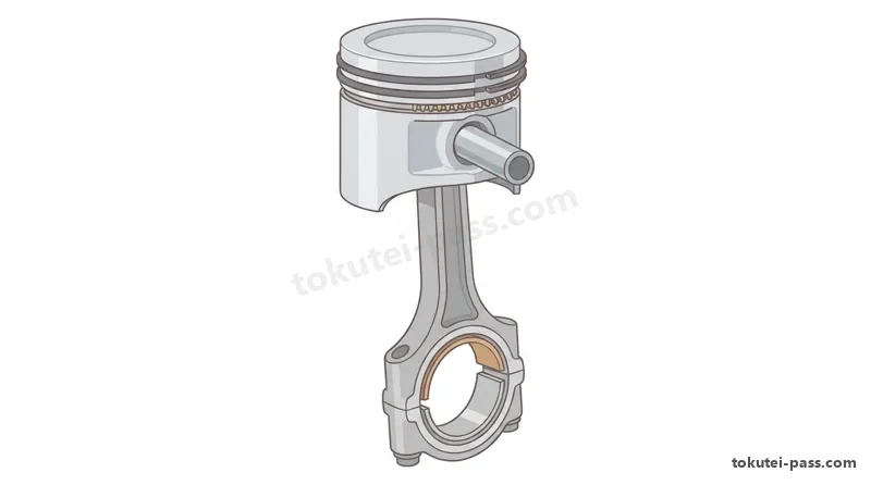
アルミニウム合金製ピストンは熱膨張を考慮して、常温時にはピストン・ピン方向の直径をスラスト方向よりわずかに小さくした楕円形(オーバル形)や、頭部を細くしたテーパ形に仕上げられています。
Accounting for thermal expansion, aluminum-alloy pistons are machined into an oval shape at room temperature (slightly smaller diameter along the piston pin axis than the thrust axis) and tapered narrower toward the crown.
ピストン・リングのうち「コンプレッション・リング」は、シリンダ壁面とピストンとの間の気密を保つ働きと、燃焼によりピストンが受ける熱の大半をシリンダ壁へ伝えて逃がす役目をしています。
Among piston rings, the 'compression ring' serves two roles: maintaining an airtight seal between the cylinder wall and piston, and conducting most of the combustion heat absorbed by the piston out to the cylinder wall.
外周面に角度をつけた「テーパ・フェース型」のコンプレッション・リングは、なじみ性と油かき性能に優れ、一般に「セカンド・リング」に用いられます。また「オイル・リング(組み合わせ式)」は特殊鋳鉄ではなく、一般に「炭素鋼(スチール)」で作られています。
A 'taper-face' compression ring with an angled outer face offers superior break-in and oil-scraping performance and is generally used as the 'second ring'. Also, three-piece 'oil rings' are generally made of 'carbon steel' rather than special cast iron.
シリンダ壁面の油膜が切れてピストン・リングとシリンダ壁面が直接接触し、局部的な高温・溶着によってリングやシリンダの表面に引っかき傷ができる現象を「スカッフ現象(スカッフィング)」といいます。
When the oil film on the cylinder wall breaks down and the piston ring contacts the cylinder wall directly, localized high heat and seizure create scratch marks on the ring and cylinder surfaces—a phenomenon called 'scuffing'.
高速回転時にピストン・リングがリング溝内で上下に激しく振動して気密が保てなくなる現象を「フラッタ現象」といい、オイル消費量増大や出力低下の原因となります。
At high engine speeds, vertical vibration of the piston ring inside its groove that breaks the gas seal is called 'ring flutter', causing increased oil consumption and reduced power output.
Key points
- コンプレッション・リングは「気密保持」と「ピストンの熱をシリンダへ伝える放熱作用」の2つの役目を持つ。
Compression rings perform two functions: 'maintaining gas sealing' and 'transferring piston heat to the cylinder wall'. - テーパ・フェース型は一般にセカンド・リングに用いられ、オイル・リングは一般に「炭素鋼(鋼製)」で作られている(特殊鋳鉄は誤り)。
Taper-face rings are generally used for the second ring, and oil rings are generally made of 'carbon steel' ('special cast iron' is incorrect). - スカッフ現象とは、シリンダ壁面の油膜が切れてリングと壁面が直接接触し、表面に引っかき傷ができることをいう。
Scuffing occurs when the oil film on the cylinder wall breaks down, causing direct metal contact and scratch marks on the ring and cylinder wall.
| Word | Meaning |
|---|---|
| コンプレッション・リングとオイル・リング | compression ring and oil ring |
| テーパ・フェース型 | taper-face type ring |
| スカッフ現象 | scuffing phenomenon |
| フラッタ現象 | ring flutter phenomenon |
コンロッド・ベアリング(クラッシュ・ハイト、張り、軸受材料)とトーショナル・ダンパ
Connecting Rod Bearings (Crush Height, Spread, Bearing Materials) and Torsional Damper
コンロッド大端部に組み込まれる半割り形の「コンロッド・ベアリング」には、ハウジング内面に密着させて熱伝導を良くし回り止めとするため、半円周よりわずかに長く突出させた「クラッシュ・ハイト」が設けられています。
Half-shell 'connecting rod bearings' fitted into the connecting rod big end are given a slight protrusion beyond a semicircle called 'crush height', ensuring the bearing back presses tightly against the housing bore for good heat transfer and anti-rotation.
クラッシュ・ハイトが「大き過ぎると」組み付け時にベアリングにたわみが生じて局部的に荷重が掛かり早期疲労・破損の原因となり、逆に「小さ過ぎると」密着不良で放熱性が悪化しベアリングが共回りします。
If crush height is 'too large', assembling the cap causes the bearing shell to buckle and bear localized loads, leading to early fatigue and failure; conversely, if 'too small', poor contact reduces heat dissipation and allows the bearing to spin.
またベアリングの「張り(スプレッド)」は、組み付ける前のベアリング外径をハウジング内径より少し広げておくもので、圧縮されるにつれてベアリングの両端が内側に曲がり込むのを防止しています。
Bearing 'spread' means making the free outer diameter slightly wider than the housing bore before installation, preventing the bearing ends from curving inward as the cap is compressed during assembly.
軸受材料のうち「トリメタル(三層メタル)」は、鋼製裏金に銅と20%〜30%の鉛の合金(ケルメット・メタル)を焼結し、その上に鉛とすず(またはインジウム)の合金をめっきしたものです。アルミニウム合金メタルは、すずの含有率が高いものほど熱膨張が大きいためオイル・クリアランスを大きくしています。
'Tri-metal' bearings sinter a copper-lead alloy (20%–30% lead, Kelmet) onto a steel backing and electroplate a lead-tin (or lead-indium) overlay. In aluminum-alloy bearings, higher tin (Sn) content increases thermal expansion, requiring a larger oil clearance than low-tin types.
クランクシャフトの前端部に設けられる「トーショナル・ダンパ」は、ゴムなどの弾性体の働きによってクランクシャフトの「ねじり振動」を吸収し、共振による破損や騒音を防ぐ装置です。
The 'torsional damper' mounted at the front end of the crankshaft uses an elastic rubber element to absorb 'torsional vibration' (twisting vibration) of the crankshaft, preventing resonance breakage and noise.
Key points
- クラッシュ・ハイトが「大き過ぎると」たわみが生じて局部荷重が掛かり、「小さ過ぎると」密着・放熱不良や回り止め不良となる。
Excessively 'large' crush height causes buckling and localized loading; 'too small' causes poor contact, poor cooling, and bearing rotation. - ベアリングの「張り」は組み付け時に内側へ曲がり込むのを防ぎ、すず含有率が高いアルミ合金メタルはオイル・クリアランスを大きくする。
Bearing 'spread' prevents inward curling during assembly; high-tin aluminum alloy bearings require a larger oil clearance. - クランクシャフトのトーショナル・ダンパは、クランクシャフトの「ねじり振動」を吸収する(軸方向振動ではない)。
The crankshaft torsional damper absorbs 'torsional (twisting) vibration' of the crankshaft (not axial vibration).
| Word | Meaning |
|---|---|
| クラッシュ・ハイトと張り | crush height and bearing spread |
| トリメタル(三層メタル・ケルメット) | tri-metal bearing (Kelmet alloy) |
| アルミニウム合金メタル | aluminum-alloy bearing |
| トーショナル・ダンパ(ねじり振動吸収) | torsional damper (twisting vibration absorber) |
バルブ・タイミング、バルブ・オーバラップ、点火順序とクランク回転角の計算
Valve Timing, Valve Overlap, Firing Order, and Crankshaft Angle Calculations
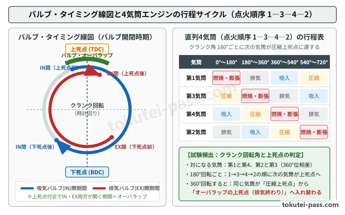
4サイクル・エンジンでは吸排気の慣性効果を利用して充填効率を高めるため、インテーク・バルブは排気上死点前に開いて吸入下死点後に閉じ、エキゾースト・バルブは膨張下死点前に開いて排気上死点後に閉じます。
In a 4-stroke engine, to utilize intake and exhaust gas inertia for higher charging efficiency, the intake valve opens before exhaust TDC and closes after intake BDC, while the exhaust valve opens before expansion BDC and closes after exhaust TDC.
そのため排気行程の終期(上死点付近)には、インテーク・バルブとエキゾースト・バルブの両方が同時に開いている期間があり、これを「バルブ・オーバラップ」と呼びます。
Consequently, near top dead center at the end of the exhaust stroke, there is a period when both the intake and exhaust valves are open simultaneously, known as 'valve overlap'.
点火順序が「1―3―4―2」の4サイクル直列4シリンダ・エンジンでは、クランクシャフトが720°(2回転)する間に4気筒が一巡するため、180°回転ごとに「1→3→4→2」の順で次の気筒が圧縮上死点に達します。
In a 4-stroke inline 4-cylinder engine with firing order '1―3―4―2', all 4 cylinders fire once every 720° (two crankshaft revolutions), so the next cylinder in the sequence '1 → 3 → 4 → 2' reaches compression TDC every 180° of crank rotation.
また「第1気筒と第4気筒」「第2気筒と第3気筒」はピストンが同じ位置(360°位相差)で動く対になっており、一方が「圧縮上死点」にあるとき、もう一方は必ず「オーバラップの上死点」にあります。
Furthermore, 'Cylinders 1 & 4' and 'Cylinders 2 & 3' move as companion pairs at the same piston position (360° out of phase): whenever one cylinder is at 'compression TDC', its companion cylinder is always at 'overlap TDC'.
ある気筒が圧縮上死点(0°)にある状態からクランクを360°回すと、その気筒自身が「オーバラップの上死点」に移り、540°(180°+360°)回すと、点火順序で1つ次の気筒が「オーバラップの上死点」に達します。
Starting with a given cylinder at compression TDC (0°), rotating the crankshaft 360° brings that same cylinder to 'overlap TDC', and rotating 540° (180° + 360°) brings the next cylinder in the firing order to 'overlap TDC'.
Key points
- 点火順序「1―3―4―2」では、180°ごとに次の気筒が圧縮上死点になり、対の気筒(1と4、2と3)は圧縮上死点とオーバラップ上死点が逆になる。
With firing order '1―3―4―2', the next cylinder reaches compression TDC every 180°, and companion cylinders (1–4, 2–3) are opposite between compression TDC and overlap TDC. - クランクを360°回すと同じ気筒の圧縮上死点とオーバラップ上死点が入れ替わり、540°回すと180°後の気筒がオーバラップ上死点になる。
Rotating 360° swaps compression TDC and overlap TDC for the same cylinder; rotating 540° puts the cylinder 180° behind into overlap TDC. - 【例】点火順序 1―3―4―2 で第4気筒が圧縮上死点から 540°回転 → 180°で第2気筒が圧縮上死点になり、さらに 360°(計 540°)で「第2気筒」がオーバラップ上死点(圧縮上死点は対の第3気筒)
Example: With firing order 1―3―4―2, rotating 540° from Cylinder 4 at compression TDC → Cylinder 2 reaches compression TDC at 180° and moves to overlap TDC after another 360° (total 540°; Cylinder 3 is at compression TDC) - 【例】点火順序 1―3―4―2 で第1気筒が圧縮上死点から 180°回転 → 次の第3気筒が圧縮上死点となり、その対である「第2気筒」がオーバラップ上死点になる
Example: With firing order 1―3―4―2, rotating 180° from Cylinder 1 at compression TDC → Next Cylinder 3 reaches compression TDC, and its companion 'Cylinder 2' is at overlap TDC
| Word | Meaning |
|---|---|
| バルブ・タイミング | valve timing |
| バルブ・オーバラップ | valve overlap |
| 圧縮上死点とオーバラップの上死点 | compression TDC and overlap TDC |
| 点火順序(1―3―4―2) | firing order (1―3―4―2) |
油圧式可変バルブ・タイミング機構(VVT)と過給機(ターボ・スーパ・チャージャ)
Hydraulic Variable Valve Timing (VVT) and Superchargers (Turbo & Roots Supercharger)
インテーク側に設けられた油圧式の可変バルブ・タイミング機構(VVT)は、カムシャフト前部のタイミング・スプロケット(プーリ)部に設けた「バルブ・タイミング・コントローラ」に油圧を作用させて制御します。
A hydraulic Variable Valve Timing (VVT) mechanism on the intake camshaft is controlled by applying hydraulic oil pressure to a 'valve timing controller' mounted at the camshaft timing sprocket (pulley) at the front of the camshaft.
この機構は、バルブの作動角(開いている角度幅)は「一定のまま」、クランクシャフトに対するカムシャフトの位相を変化させることで、インテーク・バルブの開閉時期を進角(早める)または遅角(遅らせる)させます。
While keeping the valve operating angle (lift duration) 'constant', this mechanism alters the phase of the camshaft relative to the crankshaft to advance (open/close earlier) or retard (open/close later) the intake valve timing.
中負荷・中速域では「進角」させて開く時期を早め、オーバラップ量を多くして内部EGR効果や体積効率を高めます。一方、アイドリング時はオーバラップをなくして安定させ、高速回転時は「遅角」させて閉じる時期を遅らせ吸気慣性で体積効率を高めます。
At medium speed and load, timing is 'advanced' to open the intake valve earlier, increasing overlap to boost internal EGR and volumetric efficiency. At idle, overlap is eliminated for stability, and at high speed, timing is 'retarded' to delay intake valve closing and use intake inertia.
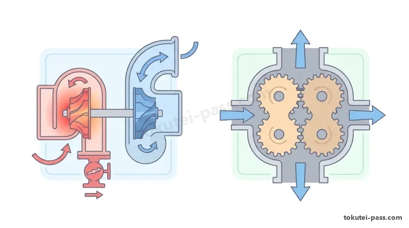
過給機のうち「ターボ・チャージャ」は排気エネルギーでタービンを回す方式で、コンプレッサ・ホイールとタービン・ホイールは1本の軸で直結され「同回転」で回ります。小型軽量ですが低速域からの立ち上がりに遅れ(ターボ・ラグ)が生じやすい特徴があります。
Among forced-induction devices, a 'turbocharger' uses exhaust energy to spin a turbine; the compressor wheel and turbine wheel are joined on one shaft and rotate at the 'same speed'. It is compact and light, but prone to response delay (turbo lag) at low speeds.
エンジン回転で直接駆動する「2葉ルーツ式スーパ・チャージャ」では、まゆ形の2個のロータが回転し、ロータ1回転につき合計「4回(片側2回ずつ)」の吸入・吐出が行われます。過給圧が規定値になるとエア・バイパス・バルブが開いて過給圧の一部を吸入側へ逃がします。
In a mechanically driven 'two-lobe Roots supercharger', two figure-eight rotors mesh and perform a total of '4 intake/discharge cycles' per rotor revolution (2 per rotor). When boost pressure reaches the specified value, an air bypass valve opens to release excess pressure back to the intake side.
Key points
- 油圧式VVTはカムシャフト前部にコントローラを設け、作動角は一定のままカムの位相を変化させる(進角時=開く時期が早まりオーバラップ増大)。
Hydraulic VVT locates the controller at the front of the camshaft and changes cam phase while keeping operating angle constant (advancing opens the intake valve earlier and increases overlap). - ターボ・チャージャのコンプレッサ・ホイールとタービン・ホイールは同回転であり、過給圧制御にはウエスト・ゲート・バルブを用いる。
A turbocharger's compressor wheel and turbine wheel rotate at the same speed, using a wastegate valve to control boost pressure. - 2葉ルーツ式スーパ・チャージャはロータ1回転につき「4回」の吸入・吐出を行い、エア・バイパス・バルブで過給圧を制御する。
A two-lobe Roots supercharger performs '4' intake/discharge cycles per rotor revolution and controls boost via an air bypass valve.
| Word | Meaning |
|---|---|
| 可変バルブ・タイミング機構(VVT) | variable valve timing mechanism (VVT) |
| バルブ・タイミング・コントローラ | valve timing controller |
| ターボ・チャージャとウエスト・ゲート・バルブ | turbocharger and wastegate valve |
| 2葉ルーツ式スーパ・チャージャとエア・バイパス・バルブ | two-lobe Roots supercharger and air bypass valve |
ガソリン排気ガスの発生特性・三元触媒とジーゼル(コモンレール・DPF・尿素SCR)
Gasoline Exhaust Characteristics, Three-Way Catalyst, and Diesel (Common Rail, DPF, Urea SCR)
ガソリン・エンジンの正常な燃焼では、空気中の窒素(N₂)・酸素(O₂)とガソリンの炭化水素(HC)が反応し、排気ガスの大半は無害な二酸化炭素(CO₂)と水(H₂O)になりますが、一部有害なCO(一酸化炭素)・HC・NOx(窒素酸化物)が発生します。
In normal gasoline combustion, nitrogen (N₂) and oxygen (O₂) in air react with fuel hydrocarbons (HC) so most exhaust gas becomes harmless carbon dioxide (CO₂) and water (H₂O), along with small amounts of harmful CO, HC, and NOx (nitrogen oxides).
NOxは燃焼ガス温度が「高いほど」、かつ酸素がある状態(理論空燃比14.7よりやや薄い15.5付近)で多量に発生します。逆に理論空燃比より「濃い」空燃比域では、燃焼温度が下がり酸素が不足するためNOxは減少し、COとHCが増加します。
NOx is generated in larger quantities as combustion gas temperature becomes 'higher' with excess oxygen present (peaking slightly leaner than the 14.7:1 stoichiometric ratio, around 15.5:1). Conversely, in mixtures 'richer' than stoichiometric, lower combustion temperatures and lack of oxygen reduce NOx while increasing CO and HC.
「三元触媒」は理論空燃比(約14.7:1)付近の狭い領域で、CO・HCの酸化とNOxの還元の3つを同時に効率よく行います。また「EGR(排気再循環)装置」は不活性な排気ガスの一部を吸気系へ戻し、最高燃焼温度を下げてNOxを低減します。
A 'three-way catalyst' simultaneously oxidizes CO and HC and reduces NOx with high efficiency within a narrow window around the 'stoichiometric air-fuel ratio (approx. 14.7:1)'. An 'EGR (Exhaust Gas Recirculation) system' recirculates inert exhaust gas into the intake to lower peak combustion temperature and reduce NOx.
ジーゼル・エンジンの「コモンレール式燃料噴射装置」は、サプライ・ポンプで高圧化した燃料をコモンレールに蓄圧し、ECUがインジェクタを制御してメイン噴射の前に少量の「パイロット噴射」を行うことで、着火遅れを短くし騒音とNOxを抑えます。
In a diesel 'common-rail fuel injection system', high-pressure fuel from a supply pump is stored in a common rail, and the ECU triggers a small 'pilot injection' ahead of main injection to shorten ignition delay, reducing combustion noise and NOx.
ジーゼル排気の後処理装置として、PM(粒子状物質)を捕集して燃焼除去する「DPF」と、排気管内に尿素水を噴射し加水分解で生じたアンモニア(NH₃)でNOxを無害な窒素(N₂)と水(H₂O)に還元する「尿素SCRシステム」が使われます。
Diesel exhaust aftertreatment uses a 'DPF' to trap and burn off particulate matter (PM), and a 'urea SCR system' that sprays aqueous urea into the exhaust pipe so hydrolyzed ammonia (NH₃) reduces NOx into harmless nitrogen (N₂) and water (H₂O).
Key points
- NOxは燃焼ガス温度が「高いほど」多量に発生し、理論空燃比より濃い領域ではNOxが減少してCO・HCが増加する。
NOx increases as combustion gas temperature gets 'higher'; in mixtures richer than stoichiometric, NOx decreases while CO and HC increase. - 三元触媒は「理論空燃比(14.7:1)付近」でCO・HC・NOxを同時浄化し、EGRは燃焼温度を下げてNOxを抑制する。
A three-way catalyst purifies CO, HC, and NOx simultaneously near the 'stoichiometric ratio (14.7:1)'; EGR lowers combustion temperature to suppress NOx. - コモンレール式のパイロット噴射は着火遅れを短くし、DPFはPMを捕集燃焼し、尿素SCRはアンモニアでNOxを還元する。
Common-rail pilot injection shortens ignition delay, DPF traps and burns PM, and urea SCR reduces NOx using ammonia.
| Word | Meaning |
|---|---|
| 理論空燃比と三元触媒 | stoichiometric air-fuel ratio and three-way catalyst |
| 排気再循環装置(EGR) | exhaust gas recirculation (EGR) |
| コモンレール式とパイロット噴射 | common-rail system and pilot injection |
| DPFと尿素SCRシステム | DPF and urea SCR system |
試験によく出るポイントと覚え方
Common Exam Points & Memory Tips
エンジン性能では「ピストン摩擦+ウォータ・ポンプ駆動=機械損失(熱損失ではない)」、コンロッド・ベアリングでは「クラッシュ・ハイトが大き過ぎるとたわんで局部荷重・小さ過ぎると密着不良」、オイル・リングの材質は「炭素鋼(特殊鋳鉄は×)」が頻出の引っ掛けです。
Frequent exam traps: 'Piston friction + water pump/alternator drive = Mechanical loss (not heat loss)', 'Excessively large connecting-rod bearing crush height causes buckling and local load (not too small)', and 'Oil rings are made of carbon steel (special cast iron is false)'.
点火順序「1―3―4―2」の角度問題は、「180°ごとに1→3→4→2の順で次へ進み、360°で圧縮上死点とオーバラップ上死点が裏返る」と覚えれば一瞬で解けます(540°回転=1つ次の気筒がオーバラップ上死点)。
For '1―3―4―2' firing-order crank angle problems, remember: 'Advance to the next cylinder in 1→3→4→2 every 180°, and flip compression TDC to overlap TDC every 360°'. Thus, rotating 540° (= 180° + 360°) from Cylinder 4 at compression TDC puts the next cylinder, 'Cylinder 2', at overlap TDC!
また「NOxは燃焼温度が高いほど増える(低いほど増えるは×)」「2葉ルーツ式スーパ・チャージャはロータ1回転につき4回吸入・吐出(1回は×)」「VVTは作動角一定でカムの位相を変える」を確実に押さえましょう。
Also lock in: 'NOx increases at HIGHER combustion temperatures (lower is false)', 'A two-lobe Roots supercharger performs 4 intake/discharge cycles per rotor turn (1 cycle is false)', and 'VVT keeps operating angle constant while varying cam phase'.
Key points
- 平均有効圧力=1サイクルの仕事÷行程容積/摩擦損失と補機駆動損失は「機械損失」。
Mean effective pressure = Work per cycle ÷ Stroke volume / Friction & auxiliary drive losses are 'Mechanical Loss'. - クラッシュ・ハイト過大=たわみ・局部荷重/張り=内側への曲がり込み防止/オイル・リング=炭素鋼。
Excessive crush height = buckling & local load / Spread = prevents inward curling / Oil ring material = Carbon steel. - スキッシュ・エリア:クリアランスが小さいほど流速が速く、燃焼時間を短縮してノッキングを防ぐ。
Squish area: Smaller clearance yields faster vortex velocity, shortening combustion time to prevent knocking. - 1―3―4―2の540°回転:第4気筒が圧縮上死点から540°回すと、第2気筒がオーバラップの上死点になる。
540° rotation in 1―3―4―2: Rotating 540° from Cylinder 4 at compression TDC puts Cylinder 2 at overlap TDC. - NOxは燃焼温度が高いほど増加/2葉ルーツ式は1回転4回吐出/トーショナル・ダンパは「ねじり振動」を吸収。
NOx rises at high combustion temp / 2-lobe Roots = 4 cycles per revolution / Torsional damper absorbs 'torsional vibration'.
| Word | Meaning |
|---|---|
| 機械損失と熱損失 | mechanical loss and heat loss |
| クラッシュ・ハイト | connecting rod bearing crush height |
| オーバラップの上死点 | overlap top dead center |
| 2葉ルーツ式スーパ・チャージャ | two-lobe Roots supercharger |
Engine Structure & Performance
Practice this chapter in the appOfficial references
- 国土交通省「自動車整備分野特定技能2号評価試験実施要領」および日本自動車整備振興会連合会(JASPA)学科試験サンプル問題 — https://www.mlit.go.jp/jidosha/jidosha_fr10_000041.html