
Electrical Equipment, Electronic Control Systems, and External Diagnostic Testers
電装品・電子制御装置・外部診断器
Automobile Maintenance (SSW 2) · 自動車整備分野(2号) · Written by Tokutei Pass based on the official study texts; not copied verbatim.
鉛バッテリの放電特性・比重・起電力と容量計算
Lead-Acid Battery Discharge Characteristics, Specific Gravity, EMF, and Capacity Calculation
自動車用の「鉛バッテリ」は、1セルあたりの公称電圧が約2.0V(起電力は約2.1V)であり、6セルを直列に接続して12Vバッテリを構成している。
An automotive 'lead-acid battery' has a nominal voltage of approximately 2.0V per cell (electromotive force of about 2.1V), with 6 cells connected in series to form a 12V battery.
「5時間率容量」とは、周囲温度25℃において一定電流で5時間連続放電し、1セルあたりの「放電終止電圧が1.75V(6セル全体で10.5V)」に達するまでの電気量(Ah=電流A×時間h)を表す。
The '5-hour rate capacity' represents the quantity of electricity (Ah = current A × time h) discharged continuously at a constant current for 5 hours at an ambient temperature of 25℃ until the 'final discharge voltage reaches 1.75V per cell (10.5V across all 6 cells)'.
バッテリの容量は、電解液温度が高いほど(約50℃以下の範囲で)化学反応が活発になるため「大きく」なり、逆に放電電流が大きいほど容量は「小さく」なる。
Battery capacity becomes 'larger' as electrolyte temperature increases (within the range below about 50℃) because chemical reactions become more active, and conversely becomes 'smaller' as discharge current increases.
完全充電時における電解液(希硫酸)の標準比重は「液温20℃において1.280」であり、液温が1℃上昇するごとに比重は0.0007減少するため、20℃換算式「S20=St+0.0007×(t−20)」で補正する。
The standard specific gravity of the electrolyte (dilute sulfuric acid) when fully charged is '1.280 at a liquid temperature of 20℃'; since specific gravity decreases by 0.0007 for every 1℃ rise in liquid temperature, it is corrected using the 20℃ conversion formula 'S20 = St + 0.0007 × (t − 20)'.
また、バッテリの起電力は、電解液の比重が高くなるほど、また電解液の温度が高くなるほどわずかに「上昇する」特性がある(低くなるという記述は誤り)。
Additionally, the electromotive force (EMF) of a battery has the characteristic of 'rising slightly' as electrolyte specific gravity increases and as electrolyte temperature increases (statements saying it drops are incorrect).
Key points
- 5時間率放電の放電終止電圧は「1セルあたり1.75V(12Vバッテリ全体で10.5V)」である。
The final discharge voltage for a 5-hour rate discharge is '1.75V per cell (10.5V for an entire 12V battery)'. - 電解液温度が高いほど(50℃以下)容量は大きくなり、比重・温度が高いほど起電力も高くなる。
Higher electrolyte temperature (below 50℃) yields larger capacity, and higher specific gravity and temperature yield higher electromotive force. - 完全充電時の標準比重は「20℃で1.280」であり、温度1℃につき0.0007変化する。
Standard fully charged specific gravity is '1.280 at 20℃', changing by 0.0007 per 1℃ of temperature. - 【例】5時間率容量が45Ahのバッテリを5時間で放電終止電圧(1.75V/セル)にする定格放電電流 → 45 ÷ 5 = 9A
Example: Rated discharge current bringing a battery with a 5-hour rate capacity of 45Ah to final discharge voltage (1.75V/cell) in 5 hours → 45 ÷ 5 = 9A - 【例】液温30℃での測定比重が1.273のとき、20℃換算比重S20 → 1.273 + 0.0007 ×(30 − 20)= 1.280
Example: When measured specific gravity at a liquid temperature of 30℃ is 1.273, the 20℃ converted specific gravity S20 → 1.273 + 0.0007 × (30 − 20) = 1.280
| Word | Meaning |
|---|---|
| 5時間率容量(Ah) | 5-hour rate capacity (Ah) |
| 放電終止電圧(1.75V/セル) | final discharge voltage (1.75V/cell) |
| 電解液比重(20℃で1.280) | electrolyte specific gravity (1.280 at 20℃) |
| 起電力と放電電流 | electromotive force (EMF) and discharge current |
オルタネータ(交流発電機):Y結線とΔ結線・整流・電圧調整
Alternator (AC Generator): Star (Y) vs. Delta (Δ) Connection, Rectification, and Voltage Regulation
オルタネータは、磁界を作る「ロータ・コイル(界磁コイル)」、三相交流を発生する「ステータ・コイル(電機子コイル)」、交流を直流に全波整流する「シリコン・ダイオード(レクチファイア)」、および発生電圧を一定に保つ「ICレギュレータ」で構成される。
An alternator consists of a 'rotor coil (field coil)' that creates a magnetic field, a 'stator coil (armature coil)' that generates three-phase AC, 'silicon diodes (rectifier)' that perform full-wave rectification from AC to DC, and an 'IC regulator' that keeps generated voltage constant.
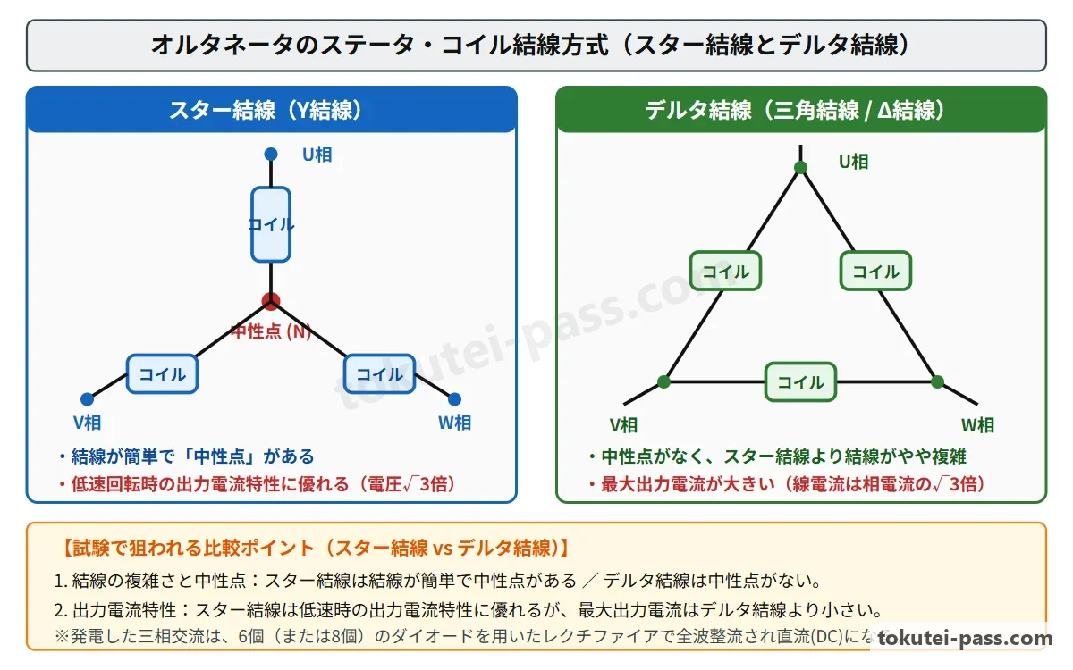
ステータ・コイルの結線方式には「星形結線(Y結線)」と「三角結線(Δ結線)」がある。Y結線はΔ結線に比べてコイルの接続が簡単であり、3つのコイルが交わる「中性点」があって中性点電圧を利用できる。
Stator coil wiring methods include 'star connection (Y connection)' and 'delta connection (Δ connection)'. Compared to Δ connection, Y connection has simpler coil connections and features a 'neutral point' where the three coils meet, allowing neutral-point voltage to be utilized.
さらにY結線は、線間電圧が相電圧の√3倍(約1.73倍)になるため「低速出力特性(低回転時の発電立ち上がり)に優れている」が、最大出力電流はΔ結線より「小さい」。
Furthermore, in a Y connection, line voltage equals √3 times (about 1.73 times) the phase voltage, giving it 'superior low-speed output characteristics (early power generation cut-in at low RPM)', though its maximum output current is 'smaller' than in a Δ connection.
一方、Δ結線は中性点を持たないが、線電流が相電流の√3倍になるため「最大出力電流が大きい」という特徴があり、大電流を必要とする車両に用いられる。
Conversely, a Δ connection has no neutral point, but its line current equals √3 times the phase current, giving it the characteristic of a 'large maximum output current' for vehicles requiring heavy electrical loads.
ICレギュレータは、ロータ・コイルに流す界磁電流をパワートランジスタで高速にON・OFF(デューティ制御)し、エンジン回転速度や電気負荷が変化しても発電電圧を約14.0V〜14.5Vの一定範囲に調整する。
The IC regulator rapidly switches the field current flowing through the rotor coil ON and OFF (duty control) using a power transistor, regulating charging voltage within a constant range of approximately 14.0V to 14.5V even when engine speed or electrical load changes.
Key points
- Y結線(星形結線)はΔ結線に比べて「コイル接続が簡単」「中性点がある」「低速出力特性に優れる」。
Compared to Δ connection, Y (star) connection features 'simpler coil connections', 'a neutral point', and 'superior low-speed output characteristics'. - 最大出力電流は、Y結線のほうがΔ結線より「小さい」(Y結線の最大出力電流が大きいという記述は誤り)。
Maximum output current is 'smaller' in a Y connection than in a Δ connection (statements claiming Y connection has a larger maximum output current are false). - ICレギュレータは「ロータ・コイル(界磁コイル)」の電流をON・OFF制御して発生電圧を一定に保つ。
The IC regulator controls the current in the 'rotor coil (field coil)' ON and OFF to keep generated voltage constant.
| Word | Meaning |
|---|---|
| 星形結線(Y結線)と中性点 | star connection (Y connection) and neutral point |
| 三角結線(Δ結線) | delta connection (Δ connection) |
| ステータ・コイルとロータ・コイル | stator coil and rotor coil |
| ICレギュレータとレクチファイア | IC regulator and rectifier |
直巻式スタータの出力特性と駆動機構
Series-Wound Starter Output Characteristics and Drive Mechanism
スタータ(始動電動機)に使われる「直巻式直流モータ」は、磁界を作るフィールド・コイル(界磁コイル)と回転するアーマチュア・コイル(電機子コイル)が「直列」に接続されているため、両方のコイルに同じ大きさの電機子電流が流れる。
In a 'series-wound DC motor' used for a starter, the field coil that creates the magnetic field and the rotating armature coil are connected in 'series', so the exact same armature current flows through both coils.
直巻式スタータの特性として、スイッチを入れた瞬間など「ピニオン回転速度が0のとき(拘束時)」は、アーマチュアの回転による「逆起電力が0」であるため、電機子電流が「最大」となり、発生する駆動トルク(回転力)も「最大」となる。
As a key characteristic of a series-wound starter, at the instant the switch is turned on when 'pinion rotational speed is 0 (locked state)', 'counter-electromotive force (counter-EMF) is 0', so armature current is at its 'maximum' and generated drive torque is also at its 'maximum'.
その後、ピニオン回転速度が上昇するにつれて逆起電力が大きくなるため、電機子電流は減少し、それに伴ってトルクも急激に減少する。なお、スタータの出力(kW)は回転速度0のとき0であり、中程度の電流付近で最大となる。
Thereafter, as pinion rotational speed increases, counter-EMF grows larger, causing armature current to decrease and torque to drop sharply along with it. Note that starter output power (kW) is 0 when rotational speed is 0, and reaches its peak at an intermediate current level.
マグネット・スイッチは、ピニオンをリング・ギヤに押し出す「プルイン・コイル」と位置を保持する「ホールディング・コイル」を備え、メイン接点が閉じるとプルイン・コイルには電流が流れなくなる。
The magnetic switch is equipped with a 'pull-in coil' that pushes the pinion into mesh with the ring gear and a 'hold-in coil' that holds its position; once the main contact closes, current stops flowing through the pull-in coil.
また「オーバランニング・クラッチ」は、エンジン始動後にリング・ギヤがピニオンより速く回転した際に空転(一方向クラッチ作用)し、アーマチュアの過回転による破損を防止する。
Additionally, the 'overrunning clutch' freewheels (acts as a one-way clutch) when the ring gear spins faster than the pinion after engine start, preventing armature damage from overspeeding.
Key points
- 直巻式スタータは、ピニオン回転速度が「0のとき」に逆起電力が0となるため、電機子電流が「最大」でトルクも「最大」になる。
In a series-wound starter, when pinion speed is '0', counter-EMF is 0, so armature current is 'maximum' and torque is also 'maximum'. - ピニオン回転速度が上昇するほど逆起電力が増加し、電機子電流とトルクは減少する。
As pinion rotational speed increases, counter-EMF increases, while armature current and torque decrease. - オーバランニング・クラッチは、エンジン始動後にリング・ギヤからアーマチュアが逆駆動されて過回転するのを防ぐ。
The overrunning clutch prevents the armature from being back-driven and overspun by the ring gear after the engine starts.
| Word | Meaning |
|---|---|
| 直巻式スタータ | series-wound starter |
| 逆起電力と電機子電流 | counter-electromotive force and armature current |
| マグネット・スイッチ | magnetic switch |
| オーバランニング・クラッチ | overrunning clutch |
点火時期制御(ESA)・通電角制御とスパーク・プラグの熱価
Ignition Timing Control (ESA), Dwell Angle Control, and Spark Plug Heat Range
電子制御式点火装置(ESA)において、エンジンECUは「吸入空気量(または吸気管圧力)」と「エンジン回転速度」から基本点火時期を算出し、冷却水温やノック・センサ信号に応じて補正(ノッキング発生時は遅角)を行う。
In an Electronic Spark Advance (ESA) system, the engine ECU calculates basic ignition timing from 'intake air quantity (or intake manifold pressure)' and 'engine speed', then applies corrections based on coolant temperature and knock sensor signals (retarding timing when knocking occurs).
「アイドル安定化制御」では、エアコン負荷などでアイドル回転速度が目標回転速度より低下した際、点火時期を「進角」させることで燃焼トルクを高め、回転速度の変動を防止する。
In 'idle stabilization control', when idle speed drops below the target speed due to air conditioner load or similar factors, the ECU 'advances' ignition timing to boost combustion torque and prevent speed fluctuations.
また「通電角(ドエル・アングル)制御」では、エンジン回転速度が上昇するとイグニッション・コイルの一次電流が流れる時間が短くなるため、パワートランジスタの「ON時期(通電開始時期)を早める」ことで十分な一次電流と二次電圧を確保する。
In 'dwell angle (primary current conduction) control', as engine speed rises, the time available for primary current to flow through the ignition coil shortens; therefore, the ECU 'advances the ON timing (starts conduction earlier)' of the power transistor to secure sufficient primary current and secondary voltage.
スパーク・プラグの「熱価(放熱の度合い)」において、「低熱価型(焼け型)」は高熱価型(冷え型)に比べて「がいし脚部(絶縁体先端)が長く、ガス室の容積が大きい」ため、熱が逃げにくく、低速走行でも自己清浄温度(約450〜500℃)に達しやすい。
Regarding spark plug 'heat range (degree of heat dissipation)', a 'low heat range (hot type)' plug has a 'longer insulator foot (tip) and a larger gas pocket volume' compared to a high heat range (cold type) plug, making heat harder to escape so it easily reaches self-cleaning temperature (approx. 450–500℃) even during low-speed driving.
逆に「高熱価型(冷え型)」はがいし脚部が短くガス室が小さいため熱が逃げやすく、高速・高負荷連続運転時の過熱によるプレイグニッション(早期着火)を防ぐことができる。
Conversely, a 'high heat range (cold type)' plug has a shorter insulator foot and smaller gas pocket so heat dissipates quickly, preventing pre-ignition caused by overheating during continuous high-speed, heavy-load operation.
Key points
- アイドル安定化制御は、アイドル回転低下時に点火時期を「進角」させて回転変動を防ぐ。
Idle stabilization control 'advances' ignition timing when idle speed drops to prevent speed fluctuation. - 通電角制御は、回転速度の上昇に伴いパワートランジスタの「ON時期を早めて」一次電流の低下を防ぐ(OFF時期を遅らせると点火時期が狂うため誤り)。
Dwell angle control 'makes the power transistor ON timing earlier' as engine speed rises to prevent primary current drop (delaying OFF timing is incorrect as it alters ignition timing). - 低熱価型(焼け型)プラグは、高熱価型(冷え型)に比べて「がいし脚部が長く、ガス室が大きい」ため熱が逃げにくい。
A low heat range (hot type) spark plug has a 'longer insulator foot and larger gas pocket' than a high heat range (cold type) plug, retaining heat more easily.
| Word | Meaning |
|---|---|
| 電子制御式点火時期制御(ESA) | Electronic Spark Advance (ESA) |
| アイドル安定化制御(進角) | idle stabilization control (timing advance) |
| 通電角制御 | dwell angle control |
| 低熱価型(焼け型)と高熱価型(冷え型) | low heat range (hot type) and high heat range (cold type) |
電子制御式燃料噴射装置(EFI)の各種センサ特性
Characteristics of Electronic Fuel Injection (EFI) Sensors
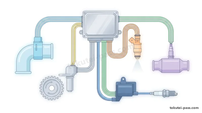
D-ジェトロニック方式で吸入空気量を間接的に検出する「バキューム・センサ(吸気管圧力センサ)」は、シリコン・チップのピエゾ抵抗効果を利用しており、「吸気管絶対圧力が高くなる(大気圧に近づく)ほど出力電圧が高くなる」特性を持つ。
A 'vacuum sensor (intake manifold pressure sensor)' that indirectly detects intake air quantity in a D-Jetronic system uses the piezo-resistive effect of a silicon chip and has the characteristic that 'output voltage increases as intake manifold absolute pressure increases (approaches atmospheric pressure)'.
スロットル・バルブの開度を非接触で検出する「ホール素子式スロットル・ポジション・センサ」は、スロットル・シャフトと共に回転する永久磁石によってホールICを貫く磁束密度が変化し、開度に比例した電圧を出力する。
A 'Hall-effect throttle position sensor' that detects throttle valve opening without contact varies the magnetic flux density passing through a Hall IC via a permanent magnet rotating with the throttle shaft, outputting a voltage proportional to throttle opening.
排気ガス中の酸素濃度を検出する「ジルコニア式O₂センサ」は、排気ガスと大気との「酸素濃度差が大きいとき(理論空燃比14.7よりリッチ側)」に約1Vの起電力を発生し、リーン側では約0Vとなる。
A 'zirconia O₂ sensor' that detects oxygen concentration in exhaust gas generates an electromotive force of about 1V when the 'oxygen concentration difference between exhaust gas and the atmosphere is large (on the rich side of the stoichiometric 14.7 ratio)', and drops to about 0V on the lean side.
一方、広域の空燃比をリニア(連続的)に検出する「空燃比センサ(A/Fセンサ)」は、理論空燃比を基準として「空燃比がリーン(薄い)になるほど出力電圧(信号)が高くなる」直線的な特性を持つ。
Meanwhile, an 'air-fuel ratio sensor (A/F sensor)' that linearly (continuously) detects air-fuel ratio over a wide range has a linear characteristic where, referenced to stoichiometry, 'output voltage (signal) increases as the air-fuel ratio becomes leaner'.
なお、水温センサおよび吸気温センサには「負特性サーミスタ(NTC)」が使われており、温度が高くなるほど抵抗値が小さくなり、出力電圧が低くなる。
Note that coolant temperature sensors and intake air temperature sensors use 'negative temperature coefficient (NTC) thermistors', meaning resistance decreases and output voltage drops as temperature rises.
Key points
- バキューム・センサ(吸気管圧力センサ)は、吸気管圧力が「高くなるほど」出力電圧が「高くなる」。
Vacuum sensor (manifold pressure sensor): output voltage becomes 'higher' as intake manifold pressure becomes 'higher'. - ジルコニア式O₂センサは、大気との酸素濃度差が「大きいとき(リッチ時)」に約1Vの起電力を発生する。
Zirconia O₂ sensor: generates an EMF of about 1V when the oxygen concentration difference with the atmosphere is 'large (when rich)'. - 空燃比センサ(A/Fセンサ)は、空燃比が「リーン(薄い)になるほど」出力電圧がリニアに「高くなる」。
Air-fuel ratio (A/F) sensor: output voltage linearly becomes 'higher' as the mixture becomes 'leaner'. - 水温センサ・吸気温センサ(負特性サーミスタ)は、温度が高くなるほど抵抗値と出力電圧が「低くなる」。
Coolant and intake air temperature sensors (NTC thermistors): resistance and output voltage become 'lower' as temperature rises.
| Word | Meaning |
|---|---|
| バキューム・センサ(吸気管圧力センサ) | vacuum sensor (intake manifold pressure sensor) |
| ホール素子式スロットル・ポジション・センサ | Hall-effect throttle position sensor |
| ジルコニア式O₂センサ | zirconia O₂ sensor |
| 空燃比センサ(A/Fセンサ) | air-fuel ratio sensor (A/F sensor) |
ECUによる燃料噴射制御とフェイルセーフ・バックアップ機能
ECU Fuel Injection Control and Fail-Safe / Backup Functions
エンジンECUは、吸入空気量とエンジン回転速度から「基本噴射時間」を計算し、これに暖機増量や加速増量、空燃比フィードバック補正などを加え、さらにバッテリ電圧に応じた「無効噴射時間」を足してインジェクタの通電時間を決定する。
The engine ECU calculates 'basic injection duration' from intake air quantity and engine speed, adds warm-up enrichment, acceleration enrichment, and air-fuel ratio feedback correction, and then adds 'invalid injection duration' based on battery voltage to determine total injector energizing time.
インジェクタのニードル・バルブが開くまでの遅れ時間である「無効噴射時間」は、バッテリ電圧が低いほど長くなるため、ECUは電圧低下時に通電時間を長く補正して実際の噴射量を一定に保つ。
'Invalid injection duration' (the delay time until the injector needle valve opens) becomes longer as battery voltage drops, so the ECU lengthens energizing time during low voltage to keep actual fuel injection quantity constant.
また、スロットル全閉でのエンジン高回転減速時(フューエル・カット)や、エンジン過回転・最高速度超過時には、燃費向上やエンジン保護のためインジェクタからの燃料噴射を一時的に停止する。
Additionally, during high-RPM deceleration with the throttle fully closed (fuel cut) or when engine speed or vehicle speed exceeds the maximum limit, the ECU temporarily stops fuel injection from the injectors to improve fuel economy and protect the engine.
センサや配線に断線・短絡などの異常が発生した際、ECUがあらかじめ記憶された「標準値(例:水温センサ異常時は80℃)」に置き換えて最低限の走行を継続させる機能を「フェイルセーフ機能」という。
When an abnormality such as an open or short circuit occurs in a sensor or harness, the function in which the ECU substitutes a pre-stored 'standard value (e.g., 80℃ for a coolant temp sensor fault)' to maintain minimum drivability is called the 'fail-safe function'.
一方、ECU内部のマイクロコンピュータ(CPU)自体が暴走・故障した際に、専用のバックアップICが燃料噴射時間や点火時期を「固定値」に切り替えて退避走行を可能にする機能を「バックアップ機能」という。
Conversely, when the microcomputer (CPU) inside the ECU itself malfunctions or freezes, the function in which a dedicated backup IC switches fuel injection duration and ignition timing to 'fixed values' to enable limp-home driving is called the 'backup function'.
Key points
- 無効噴射時間はバッテリ電圧が低いほど長くなるため、ECUは通電時間を長く補正する。
Invalid injection duration increases as battery voltage drops, so the ECU compensates by lengthening injector energizing time. - センサ異常時にECUが標準値(擬似信号)で制御を続けるのが「フェイルセーフ機能」である。
Continuing control using a standard value (simulated signal) during a sensor fault is the 'fail-safe function'. - CPU自体の異常時にバックアップICが固定値で退避走行を行わせるのが「バックアップ機能」である。
Switching to fixed values via a backup IC for limp-home driving when the CPU itself fails is the 'backup function'.
| Word | Meaning |
|---|---|
| 基本噴射時間と無効噴射時間 | basic injection duration and invalid injection duration |
| 空燃比フィードバック制御 | air-fuel ratio feedback control |
| フェイルセーフ機能(標準値制御) | fail-safe function (standard value control) |
| バックアップ機能(固定値制御) | backup function (fixed value control) |
外部診断器(スキャン・ツール)の機能と故障コード消去
External Diagnostic Tester (Scan Tool) Functions and Clearing Trouble Codes
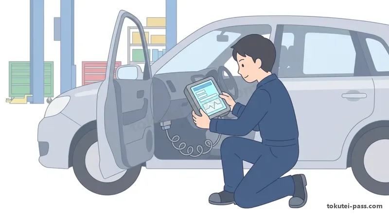
運転席足元などの「DLC(データ・リンク・コネクタ:16ピン)」に「外部診断器(スキャン・ツール)」を接続することで、車両の各ECUと通信し、高度な故障診断や整備作業サポートを行うことができる。
By connecting an 'external diagnostic tester (scan tool)' to the 'DLC (Data Link Connector: 16-pin)' near the driver's footwell, technicians can communicate with vehicle ECUs to perform advanced troubleshooting and maintenance support.
スキャン・ツールの代表的な機能には、①ダイアグノーシス・コード(DTC:故障コード)の読み取りと消去、②故障検出瞬間のエンジン状態を記録した「フリーズ・フレーム・データ」の読み取り、③リアルタイムのセンサ値を見る「データ・モニタ」がある。
Representative scan tool functions include: (1) reading and clearing Diagnostic Trouble Codes (DTCs), (2) reading 'Freeze Frame Data' that records engine conditions at the exact instant a fault was detected, and (3) 'Data Monitor' for viewing real-time sensor values.
さらに、④診断器からの操作でインジェクタや電制スロットル、電動ファンなどのアクチュエータを強制的に駆動して動作を確認する「アクティブ・テスト」や、⑤エーミング・初期学習を行う「作業サポート機能」がある。
Furthermore, there are: (4) 'Active Test', which forcibly drives actuators such as injectors, electronic throttle, or electric fans from the scan tool to verify operation, and (5) 'Work Support' functions for aiming or initial learning calibrations.
故障修理後に「外部診断器(スキャン・ツール)を用いてダイアグノーシス・コード(DTC)を消去」すると、ECUに記憶された故障コードおよびフリーズ・フレーム・データのみが消去される。
After repairing a fault, 'clearing Diagnostic Trouble Codes (DTCs) using an external diagnostic tester (scan tool)' erases only the trouble codes and Freeze Frame Data stored in the ECU.
このとき、バッテリのマイナス端子を切り離す方法とは異なり、「時計やラジオ(オーディオ)のメモリー、他の正常なシステムの学習値などはリセット(初期化)されない」という大きな利点がある。
Unlike disconnecting the negative (-) battery terminal, clearing codes with a scan tool has the major advantage that 'clock settings, radio/audio memory, and learned values of other normal systems are NOT reset (initialized)'.
Key points
- 外部診断器によるDTC消去では、故障コードとフリーズ・フレーム・データが消去されるが、「時計やオーディオ設定・学習値はリセットされない」。
Clearing DTCs with an external scan tool erases trouble codes and Freeze Frame Data, but 'does NOT reset the clock, audio settings, or learned values'. - 「フリーズ・フレーム・データ」は、ECUが異常を検出した瞬間の回転速度・水温・車速などの記録データである。
'Freeze Frame Data' is recorded data of engine speed, coolant temperature, vehicle speed, etc. at the exact moment the ECU detected an abnormality. - 「アクティブ・テスト」は、スキャン・ツールからアクチュエータを強制駆動して作動状態を点検する機能である。
'Active Test' is a function that forcibly drives actuators from the scan tool to inspect their operating condition.
| Word | Meaning |
|---|---|
| 外部診断器(スキャン・ツール)とDLC | external diagnostic tester (scan tool) and DLC |
| ダイアグノーシス・コード(DTC) | Diagnostic Trouble Code (DTC) |
| フリーズ・フレーム・データ | Freeze Frame Data |
| データ・モニタとアクティブ・テスト | Data Monitor and Active Test |
試験によく出るポイントと覚え方
Common Exam Points and How to Remember Them
2号学科試験の電装・電子制御分野では、「値が増えるか・減るか」の逆転ひっかけ問題が毎年出題されるため、各機器の特性を整理して暗記しよう。
In the electrical and electronic control section of the Type 2 written exam, reverse-trap questions asking whether a value 'increases or decreases' appear every year, so organize and memorize the characteristics of each component.
第1の鉄則はバッテリとオルタネータ・スタータである。「5時間率の終止電圧=1.75V/セル、比重=20℃で1.280、温度・比重が高い=容量・起電力も高い」「オルタネータY結線=中性点あり・低速優れる・最大電流は小さい」「直巻スタータ回転0=電流・トルク最大」と覚える。
Rule 1 covers batteries, alternators, and starters: '5-hour rate final voltage = 1.75V/cell; specific gravity = 1.280 at 20℃; higher temp & specific gravity = higher capacity & EMF', 'Alternator Y connection = has neutral point, superior low-speed output, smaller max current than Δ', 'Series-wound starter at 0 speed = max current & max torque'.
第2の鉄則は点火とプラグである。「アイドル回転低下=点火時期を進角」「高回転時の通電角制御=ON時期を早める」「低熱価型(焼け型)プラグ=がいし脚部が長くガス室が大きい」と対比して押さえよう。
Rule 2 covers ignition and spark plugs: 'Idle speed drop = advance ignition timing', 'High-RPM dwell control = make ON timing earlier', 'Low heat range (hot type) spark plug = longer insulator foot and larger gas pocket'.
第3の鉄則はセンサと外部診断器である。「バキューム・センサ=圧力高いで電圧高い」「A/Fセンサ=リーンで電圧高い」「O₂センサ=酸素濃度差大(リッチ)で約1V」「診断器でDTC消去=時計やラジオは消えない」が頻出の正解パターンである。
Rule 3 covers sensors and scan tools: 'Vacuum sensor = higher pressure gives higher voltage', 'A/F sensor = leaner mixture gives higher voltage', 'O₂ sensor = large oxygen difference (rich) outputs ~1V', 'Clearing DTCs with scan tool = clock and radio are not erased'.
Key points
- 鉛バッテリ:5時間率終止電圧1.75V/セル、比重1.280(20℃)、温度高いほど容量・起電力は大きい。
Lead-acid battery: 5-hour final voltage 1.75V/cell, specific gravity 1.280 (20℃), higher temperature (below 50℃) yields larger capacity and EMF. - オルタネータY結線:中性点あり・低速出力に優れる・最大出力電流はΔ結線より小さい。
Alternator Y connection: has neutral point, excels in low-speed output, maximum output current is smaller than Δ connection. - 直巻式スタータ:ピニオン回転0のとき逆起電力0で、電機子電流もトルクも最大。
Series-wound starter: when pinion speed is 0, counter-EMF is 0, and both armature current and torque are at maximum. - 点火・プラグ:アイドル低下時は「進角」、高回転時は「ON時期を早める」、低熱価型は「脚部が長くガス室が大きい」。
Ignition & plugs: 'advance' timing on idle drop, 'make ON timing earlier' at high RPM, low heat range plug has 'longer insulator foot and larger gas pocket'. - センサ・診断器:吸気管圧力高い=電圧高い、A/Fリーン=電圧高い、診断器DTC消去=時計・学習値は消えない。
Sensors & scan tool: higher manifold pressure = higher voltage; leaner A/F = higher voltage; scan tool DTC clear = clock/learned values are preserved.
| Word | Meaning |
|---|---|
| 放電終止電圧(1.75V) | final discharge voltage (1.75V) |
| Y結線(中性点・低速出力) | Y connection (neutral point, low-speed output) |
| 低熱価型スパーク・プラグ | low heat range (hot type) spark plug |
| ダイアグノーシス・コード消去 | clearing Diagnostic Trouble Codes (DTCs) |
Electrical, Electronic Control & Scan Tools
Practice this chapter in the appOfficial references
- 国土交通省「自動車整備分野特定技能2号評価試験実施要領」および日本自動車整備振興会連合会(JASPA)学科試験サンプル問題 — https://www.mlit.go.jp/jidosha/jidosha_fr10_000041.html