
Powertrain System (AT, CVT, Differential)
動力伝達装置(AT・CVT・差動装置)
Automobile Maintenance (SSW 2) · 自動車整備分野(2号) · Written by Tokutei Pass based on the official study texts; not copied verbatim.
トルク・コンバータの構造・トルク比・クラッチ・ポイントとロックアップ機構
Torque Converter Structure, Torque Ratio, Clutch Point, and Lock-Up Mechanism
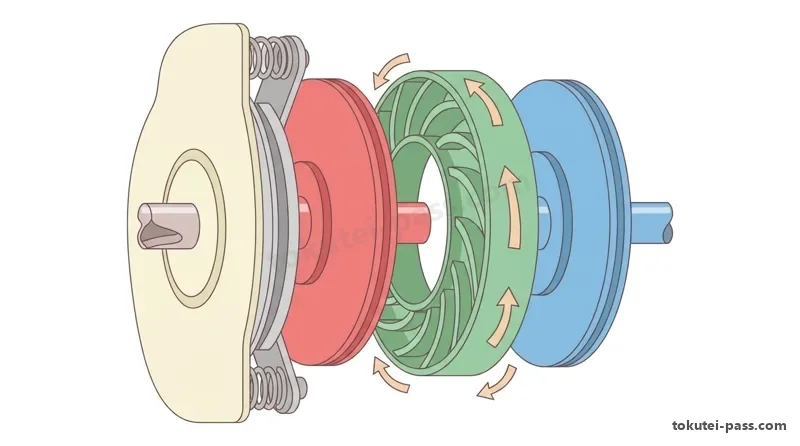
トルク・コンバータは、エンジンで駆動される「ポンプ・インペラ」、トランスミッション入力軸につながる「タービン・ランナ」、およびワンウェイ・クラッチを介してケースに支持される「ステータ」の3要素で構成され、内部のATF(自動変速機油)によって動力を伝達・増大する。
A torque converter consists of three elements: the 'pump impeller' driven by the engine, the 'turbine runner' connected to the transmission input shaft, and the 'stator' supported on the case via a one-way clutch, transmitting and multiplying power through internal ATF (Automatic Transmission Fluid).
「トルク比」とは「タービン・ランナのトルクをポンプ・インペラのトルクで除した(割った)値」であり、タービン回転速度をポンプ回転速度で割った「速度比(e)が0のとき(タービン停止・ストール時)」にトルク比は「最大(約2.0〜2.5)」となる。
'Torque ratio' is the 'value obtained by dividing turbine runner torque by pump impeller torque'; when the 'speed ratio (e = turbine speed ÷ pump speed) is 0 (turbine stopped / stall condition)', the torque ratio reaches its 'maximum (approx. 2.0–2.5)'.
タービン回転速度が上昇して速度比が大きくなるにつれてトルク比は減少し、トルク比が「1.0」に達する速度比(約0.85付近)を「クラッチ・ポイント」と呼ぶ。
As turbine speed rises and the speed ratio increases, the torque ratio decreases; the speed ratio (around 0.85) at which the torque ratio reaches '1.0' is called the 'clutch point'.
速度比がクラッチ・ポイントより小さい領域はトルク増大作用を行う「コンバータ領域」であり、クラッチ・ポイントを超えて速度比が大きい領域では、ステータがワンウェイ・クラッチにより空転して単なる流体継手として働く「カップリング領域(トルク比1.0)」となる。
The region where the speed ratio is smaller than the clutch point is the 'converter range' where torque multiplication occurs; beyond the clutch point where the speed ratio is larger, the stator freewheels via the one-way clutch and operates as a simple fluid coupling in the 'coupling range (torque ratio 1.0)'.
また「ロックアップ機構」は、高速走行時などにタービン・ハブに設けられたロックアップ・ピストンをフロント・カバーに機械的に圧着して直結(流体の滑りを0に)し、燃費を向上させる機構であり、接続時の回転衝撃は「ダンパ・スプリング」が吸収する。
Additionally, the 'lock-up mechanism' mechanically presses the lock-up piston mounted on the turbine hub against the front cover during high-speed driving to connect power directly (reducing fluid slip to zero) and improve fuel economy, while torsional shock upon engagement is absorbed by 'damper springs'.
Key points
- トルク比 = タービン・ランナのトルク ÷ ポンプ・インペラのトルクであり、速度比が「0のとき」に最大となる(速度比が最大のとき最大という記述は誤り)。
Torque ratio = Turbine runner torque ÷ Pump impeller torque, reaching its maximum when speed ratio is '0' (claiming it is maximum when speed ratio is maximum is incorrect). - トルク比が1.0になる点が「クラッチ・ポイント」であり、それより速度比が大きい領域は「カップリング領域」、小さい領域は「コンバータ領域」である。
The point where torque ratio becomes 1.0 is the 'clutch point'; the region with a higher speed ratio is the 'coupling range', and the lower region is the 'converter range'. - ロックアップ機構はロックアップ・ピストンをフロント・カバーに押し付けて機械的に動力を直結伝達する。
The lock-up mechanism presses the lock-up piston against the front cover to transmit power directly and mechanically. - 【例】ポンプ・インペラのトルクが150N・m、タービン・ランナのトルクが300N・mのとき → トルク比 = 300 ÷ 150 = 2.0
Example: When pump impeller torque is 150N・m and turbine runner torque is 300N・m → Torque ratio = 300 ÷ 150 = 2.0 - 【例】ポンプ回転速度が2,000min⁻¹、タービン回転速度が1,600min⁻¹のとき → 速度比 = 1,600 ÷ 2,000 = 0.8
Example: When pump speed is 2,000min⁻¹ and turbine speed is 1,600min⁻¹ → Speed ratio = 1,600 ÷ 2,000 = 0.8
| Word | Meaning |
|---|---|
| ポンプ・インペラ・タービン・ランナ・ステータ | pump impeller, turbine runner, stator |
| トルク比と速度比 | torque ratio and speed ratio |
| クラッチ・ポイント | clutch point |
| コンバータ領域とカップリング領域 | converter range and coupling range |
| ロックアップ・ピストンとダンパ・スプリング | lock-up piston and damper spring |
前進4段ロックアップ付き電子制御式ATの遊星歯車と摩擦要素
Planetary Gear Set and Friction Elements of an Electronic 4-Speed Lock-Up AT
電子制御式ATの変速機構には、中心の「サン・ギヤ」、その周囲を自転しながら公転する「ピニオン・ギヤ(プラネタリ・キャリアで支持)」、および外周の「リング・ギヤ(インターナル・ギヤ)」から成る「プラネタリ・ギヤ・ユニット(遊星歯車機構)」が用いられる。
The gear-shifting mechanism of an electronically controlled automatic transmission (AT) uses a 'planetary gear unit' consisting of a central 'sun gear', 'pinion gears (supported by a planetary carrier)' that rotate on their own axes while revolving around the sun gear, and an outer 'ring gear (internal gear)'.
各ギヤ要素を連結・解放する「湿式多板クラッチ」は、交互に配置されたドライブ・プレートとドリブン・プレートを油圧ピストンで圧着し、その中に組み込まれた「ディッシュ・プレート」が締結時の衝撃(ショック)を緩和する働きをする。
A 'wet multi-plate clutch' that connects or releases gear elements uses a hydraulic piston to press alternating drive plates and driven plates together, while a 'dish plate' incorporated inside acts to cushion engagement shock.
またクラッチ・ドラムの回転要素を固定する「バンド・ブレーキ」は、内面に摩擦材を貼った「ブレーキ・バンド」をドラム外周に巻き付け、油圧で作動する「サーボ・ピストン」で締め付けて回転を止める構造になっている。
Meanwhile, a 'band brake' that locks a rotating drum element consists of a 'brake band' lined with friction material wrapped around the outer circumference of the drum and tightened by a hydraulically operated 'servo piston' to stop rotation.
「ワンウェイ・クラッチ(スプラグ式またはローラ式)」は、一方向の回転のみをロックし逆方向には空転する機械的要素であり、変速時に油圧の切り替えタイミングを調整しなくても滑らかに変速させる役割を持つ。
A 'one-way clutch (sprag type or roller type)' is a mechanical element that locks rotation in one direction only and freewheels in the opposite direction, allowing smooth shifting without requiring complex hydraulic overlap timing.
AT-ECUは、車速センサやスロットル開度信号に基づいてバルブ・ボデー内のシフト・ソレノイド・バルブやリニア・ソレノイド・バルブを制御し、最適な変速段およびライン・プレッシャ(基本油圧)を作り出す。
Based on vehicle speed sensor and throttle opening signals, the AT-ECU controls shift solenoid valves and linear solenoid valves inside the valve body to produce the optimal gear stage and line pressure.
Key points
- 湿式多板クラッチの「ディッシュ・プレート」は、クラッチ締結時の衝撃を緩和し、解放時の戻りを助ける。
The 'dish plate' in a wet multi-plate clutch cushions engagement shock and assists plate return upon release. - バンド・ブレーキは「ブレーキ・バンド」と油圧で動く「サーボ・ピストン」で構成され、ドラム外周を締め付けて固定する。
A band brake consists of a 'brake band' and a hydraulically operated 'servo piston' that clamps the outer circumference of a drum. - スプラグ式ワンウェイ・クラッチは一方向の回転のみを固定し、変速ショックの軽減に用いられる。
A sprag-type one-way clutch locks rotation in one direction only and is used to reduce shift shock.
| Word | Meaning |
|---|---|
| プラネタリ・ギヤ(サン・ピニオン・リング・ギヤ) | planetary gear set (sun, pinion, and ring gears) |
| 湿式多板クラッチとディッシュ・プレート | wet multi-plate clutch and dish plate |
| バンド・ブレーキとサーボ・ピストン | band brake and servo piston |
| スプラグ式ワンウェイ・クラッチ | sprag-type one-way clutch |
スチール・ベルト式CVT(無段変速機)の構造と動力伝達作用
Steel-Belt CVT (Continuously Variable Transmission) Structure and Power Transmission
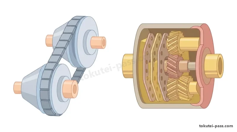
「スチール・ベルト式CVT(無段変速機)」は、入力側の「プライマリ・プーリ」と出力側の「セカンダリ・プーリ」の溝幅を油圧で連続的に変化させ、両プーリ間に巻き掛けたスチール・ベルトの接触半径を変えることで無段階に変速する。
A 'steel-belt CVT (Continuously Variable Transmission)' continuously varies the groove widths of the input-side 'primary pulley' and output-side 'secondary pulley' using hydraulic pressure, changing the contact radius of the steel belt wrapped between both pulleys to shift steplessly.
スチール・ベルトは、薄い鋼板を何層にも重ねた左右2本の「スチール・バンド(積層リング)」に、多数の「スチール・エレメント(金属コマ)」を並べて組み付けた構造になっている。
The steel belt is constructed by aligning hundreds of 'steel elements (metal blocks)' along left and right 'steel bands (laminated rings)' made of multiple layers of thin steel strips.
このスチール・ベルトによるプライマリ・プーリからセカンダリ・プーリへの動力伝達は、ベルトを引っ張るのではなく、無数の「エレメントの押し出し(圧縮)作用」によって行われる(引っ張り作用という記述は誤り)。
Power transmission from the primary pulley to the secondary pulley by this steel belt is performed not by pulling the belt, but by the 'pushing (compression) action of the steel elements' (statements describing a pulling action are incorrect).
油圧制御の役割分担として、「プライマリ・プーリ」にかける油圧によって溝幅を変えて「プーリ比(変速比)」を制御し、「セカンダリ・プーリ」にかける油圧によってベルトが滑らないよう「ベルトの張力(挟圧力)」を制御している。
Regarding the division of hydraulic control roles: hydraulic pressure applied to the 'primary pulley' changes groove width to control the 'pulley ratio (gear ratio)', while hydraulic pressure applied to the 'secondary pulley' controls 'belt tension (clamping force)' so the belt does not slip.
変速比が最も小さい「ハイ(High)側」では、プライマリ・プーリの溝幅が「狭く(接触半径が大きく)」なり、セカンダリ・プーリの溝幅が「広く(接触半径が小さく)」なる(ロー側はその逆)。
On the 'High' side where the gear ratio is smallest, the groove width of the primary pulley becomes 'narrow (large contact radius)' and the groove width of the secondary pulley becomes 'wide (small contact radius)' (and vice versa on the Low side).
Key points
- スチール・ベルト式CVTの動力伝達は、スチール・ベルトの「エレメントの押し出し(圧縮)作用」によって行われる。
Power transmission in a steel-belt CVT is accomplished by the 'pushing (compression) action of the elements' of the steel belt. - 「プライマリ・プーリ」の油圧で「プーリ比(変速比)」を制御し、「セカンダリ・プーリ」の油圧で「ベルト張力(挟圧力)」を制御する。
Hydraulic pressure at the 'primary pulley' controls the 'pulley ratio (gear ratio)', while hydraulic pressure at the 'secondary pulley' controls 'belt tension (clamping force)'. - ハイ(高速)側ではプライマリ・プーリの溝幅が「狭く(半径大)」、ロー(低速)側では「広く(半径小)」なる。
On the High (high-speed) side, the primary pulley groove width becomes 'narrow (large radius)', and on the Low (low-speed) side it becomes 'wide (small radius)'.
| Word | Meaning |
|---|---|
| スチール・ベルト(エレメントとスチール・バンド) | steel belt (elements and steel bands) |
| エレメントの押し出し作用 | pushing action of elements |
| プライマリ・プーリとセカンダリ・プーリ | primary pulley and secondary pulley |
| プーリ比(変速比)とベルト張力 | pulley ratio (gear ratio) and belt tension |
ディファレンシャルと差動制限装置(ビスカス式・ヘリカル式LSD)
Differential and Limited Slip Differentials (Viscous Coupling & Helical Gear LSD)
ディファレンシャル(差動装置)は、旋回時に生じる左右駆動輪の回転速度差を吸収する装置であり、左右のサイド・ギヤ回転速度の合計は常に「リング・ギヤ(デフ・ケース)回転速度の2倍」となる。
A differential is a device that absorbs the rotational speed difference between the left and right drive wheels during cornering; the sum of the left and right side gear rotational speeds is always 'twice the ring gear (differential case) rotational speed'.
しかし標準のディファレンシャルでは、片輪がぬかるみや凍結路で空転(スリップ)すると、もう一方の接地している駆動輪にも駆動力が伝わらなくなるため、差動を制限する「LSD(リミテッド・スリップ・デフ)」が用いられる。
However, with a standard differential, if one wheel spins (slips) on mud or ice, drive force can no longer be transmitted to the other grounded wheel; therefore, an 'LSD (Limited Slip Differential)' that restricts differential action is used.
回転差感応型の「ビスカス・カップリング式LSD」は、微小な隙間で交互に配置したインナ・プレートとアウタ・プレートの間に「高粘度シリコン・オイル」を封入した構造を持つ。
A speed-difference-sensing 'viscous coupling LSD' has a structure in which 'high-viscosity silicone oil' is sealed between inner plates and outer plates arranged alternately with tiny clearances.
ビスカス・カップリング式では、左右駆動輪の「回転速度差が大きいほど、シリコン・オイルのせん断抵抗により大きなビスカス・トルク(差動制限力)を発生し」、高回転側から低回転側へトルクを伝達する。
In a viscous coupling LSD, 'the larger the rotational speed difference between the left and right drive wheels, the larger the viscous torque (differential limiting force) generated by the shear resistance of the silicone oil', transferring torque from the faster wheel to the slower wheel.
一方、トルク感応型の「ヘリカル・ギヤ式LSD」は、プラネタリ・ギヤの「歯先とデフ・ケース内壁との摩擦抵抗」およびヘリカル・ギヤ噛み合いによるスラスト方向の摩擦抵抗を利用して差動制限力を発生させる。
Conversely, a torque-sensing 'helical gear LSD' generates differential limiting force by utilizing 'frictional resistance between the tooth tips of the planetary pinion gears and the inner wall of the diff case' as well as thrust-direction friction from helical gear meshing.
Key points
- 左右駆動輪の回転速度の和 = リング・ギヤ回転速度 × 2(片輪が停止すると他方はリング・ギヤの2倍で回転する)。
Sum of left and right drive wheel speeds = Ring gear speed × 2 (if one wheel stops, the other spins at twice the ring gear speed). - ビスカス・カップリング式LSDは高粘度シリコン・オイルが封入されており、回転速度差が「大きいほど」大きなビスカス・トルクを発生する。
A viscous coupling LSD is filled with high-viscosity silicone oil and generates a larger viscous torque as the rotational speed difference becomes 'larger'. - ヘリカル・ギヤ式LSDは、ピニオン・ギヤの「歯先とケース内壁の摩擦抵抗」およびスラスト摩擦で差動を制限する。
A helical gear LSD limits differential action via 'friction between pinion gear tooth tips and the case inner wall' and thrust friction. - 【例】リング・ギヤ回転速度が500min⁻¹で、右駆動輪が400min⁻¹のとき、左駆動輪の回転速度 → 500 × 2 − 400 = 600min⁻¹
Example: When ring gear speed is 500min⁻¹ and the right drive wheel is at 400min⁻¹, the left drive wheel speed → 500 × 2 − 400 = 600min⁻¹
| Word | Meaning |
|---|---|
| ディファレンシャル(リング・ピニオン・サイド・ギヤ) | differential (ring, pinion, and side gears) |
| 差動制限装置(LSD) | Limited Slip Differential (LSD) |
| ビスカス・カップリング式(高粘度シリコン・オイル) | viscous coupling type (high-viscosity silicone oil) |
| ヘリカル・ギヤ式LSD | helical gear LSD |
クラッチ・プロペラシャフト・等速ジョイント・4WD機構
Clutch, Propeller Shaft, Constant Velocity Joints, and 4WD Mechanisms
摩擦クラッチに広く使われる「ダイヤフラム・スプリング式クラッチ」は、コイル・スプリング式に比べてばね特性が平坦であるため、「クラッチ・ディスクのフェーシングが摩耗してもプレッシャ・プレートの圧着力がほとんど低下しない」特徴がある。
A 'diaphragm spring clutch' widely used in friction clutches has a flatter spring characteristic than a coil spring type, giving it the feature that 'pressure plate clamping force hardly drops even when the clutch disc facings wear'.
またダイヤフラム・スプリング式は高速回転時にも遠心力による圧着力低下が少なく、ペダル踏力も軽いが、機械式リンク機構ではディスクが摩耗すると「クラッチ・ペダルの遊びが小さくなる」ため点検・調整が必要である。
Furthermore, the diaphragm spring type suffers less clamping force loss from centrifugal force at high RPM and has a lighter pedal effort; however, in mechanical linkage systems, as the disc wears, 'clutch pedal free play becomes smaller', requiring inspection and adjustment.
FR車などのプロペラ・シャフトに用いられる「フック・ジョイント(カルダン・ジョイント)」は、取付角(交角)があると1回転につき2回の回転速度・トルク変動が生じるため、2個のジョイントの交角を等しく配置して変動を打ち消している。
A 'Hooke's joint (Cardan joint)' used on propeller shafts of FR vehicles produces rotational speed and torque fluctuations twice per revolution when installed at an angle, so two joints are arranged with equal angles to cancel out the fluctuations.
一方、FF車のドライブ・シャフトには交角が大きくても回転変動を生じない「等速ジョイント(CVJ)」が使われ、ホイール側(外側)には「バーフィールド型(ツェッパ型)」、デフ側(内側)には軸方向に伸縮できる「トリポード型」や「ダブル・オフセット型」が用いられる。
Meanwhile, FF vehicle drive shafts use 'Constant Velocity Joints (CVJs)' that produce no rotational fluctuation even at large angles; a 'Birfield (Rzeppa) type' is used on the wheel (outer) side, and an axially sliding 'Tripod type' or 'Double Offset type' is used on the differential (inner) side.
フルタイム4WD車には、旋回時の前後輪の回転速度差を吸収して「タイト・コーナ・ブレーキング現象」を防ぐため、前輪と後輪の間に「センタ・ディファレンシャル」または電子制御カップリングが設けられている。
Full-time 4WD vehicles are equipped with a 'center differential' or electronically controlled coupling between the front and rear wheels to absorb front-to-rear wheel speed differences during cornering and prevent the 'tight-corner braking phenomenon'.
Key points
- ダイヤフラム・スプリング式クラッチは、ディスクが摩耗しても圧着力がほとんど変化せず、摩耗するとペダルの遊びは「小さくなる」。
In a diaphragm spring clutch, clamping force hardly changes even when the disc wears, and pedal free play becomes 'smaller' as it wears. - ドライブ・シャフトの等速ジョイントは、外側に「バーフィールド型」、内側に軸方向伸縮可能な「トリポード型」などが使われる。
Drive shaft constant velocity joints use a 'Birfield type' on the outer side and an axially sliding 'Tripod type' on the inner side. - フルタイム4WDのセンタ・ディファレンシャルは、前後輪の回転差を吸収して「タイト・コーナ・ブレーキング現象」を防ぐ。
The center differential of a full-time 4WD vehicle absorbs front-to-rear rotational differences to prevent the 'tight-corner braking phenomenon'.
| Word | Meaning |
|---|---|
| ダイヤフラム・スプリング式クラッチ | diaphragm spring clutch |
| フック・ジョイントと等速ジョイント | Hooke's joint and Constant Velocity Joint (CVJ) |
| バーフィールド型とトリポード型 | Birfield type and Tripod type |
| タイト・コーナ・ブレーキング現象 | tight-corner braking phenomenon |
試験によく出るポイントと覚え方
Common Exam Points and How to Remember Them
動力伝達装置の2号学科試験では、トルク・コンバータ、電子制御AT、スチール・ベルト式CVT、およびLSDの4テーマから毎年出題されている。
In the powertrain section of the Type 2 written exam, questions appear every year from four themes: Torque Converter, Electronically Controlled AT, Steel-Belt CVT, and LSD.
トルク・コンバータは「トルク比=タービン÷ポンプ」「速度比0(タービン停止)でトルク比は最大」「トルク比1.0=クラッチ・ポイント」「それより低速=コンバータ領域、高速=カップリング領域」の4点セットを確実に覚えよう。
For the torque converter, firmly memorize the 4-point set: 'Torque ratio = Turbine ÷ Pump', 'Torque ratio is maximum at speed ratio 0 (turbine stopped)', 'Torque ratio 1.0 = Clutch point', 'Below clutch point = Converter range, above = Coupling range'.
AT・CVTでは、「多板クラッチのディッシュ・プレート=締結ショック緩和」「スチール・ベルト式CVT=エレメントの押し出し作用で伝達(引っ張りは誤り)」「プライマリ油圧=変速比、セカンダリ油圧=ベルト張力」が最頻出ポイントである。
For AT and CVT, the most frequent points are: 'Multi-plate clutch dish plate = cushions engagement shock', 'Steel-belt CVT = transmits power by pushing action of elements (pulling is false)', 'Primary hydraulic pressure = gear ratio, Secondary hydraulic pressure = belt tension'.
LSDでは、「ビスカス式=高粘度シリコン・オイル封入で、回転速度差が大きいほどビスカス・トルクも大きい」「ヘリカル式=歯先とケース内壁の摩擦およびスラスト摩擦を利用」と整理しておこう。
For LSDs, keep clear: 'Viscous type = filled with high-viscosity silicone oil, larger speed difference produces larger viscous torque', 'Helical type = uses friction between tooth tips and case inner wall plus thrust friction'.
Key points
- トルコン:トルク比=タービン÷ポンプ、速度比0でトルク比最大、クラッチ・ポイント(トルク比1.0)を超えるとカップリング領域。
Torque converter: Torque ratio = Turbine ÷ Pump; max torque ratio at speed ratio 0; beyond the clutch point (torque ratio 1.0) is the coupling range. - AT摩擦要素:ディッシュ・プレートは締結衝撃を緩和し、ロックアップ・ピストンはフロント・カバーに圧着する。
AT friction elements: Dish plate cushions engagement shock; lock-up piston presses against the front cover. - スチール・ベルト式CVT:エレメントの「押し出し作用」で動力を伝え、プライマリで変速比・セカンダリでベルト張力を制御する。
Steel-belt CVT: transmits power via the 'pushing action of elements'; primary pulley controls gear ratio, secondary pulley controls belt tension. - ビスカス式LSD:高粘度シリコン・オイルを用い、回転速度差が「大きいほど」大きなビスカス・トルクを発生する。
Viscous LSD: uses high-viscosity silicone oil, generating a larger viscous torque as rotational speed difference becomes 'larger'.
| Word | Meaning |
|---|---|
| トルク比とクラッチ・ポイント | torque ratio and clutch point |
| ディッシュ・プレート | dish plate |
| エレメントの押し出し作用 | pushing action of elements |
| ビスカス・カップリング式LSD | viscous coupling LSD |
Drivetrain (AT, CVT, Differential)
Practice this chapter in the appOfficial references
- 国土交通省「自動車整備分野特定技能2号評価試験実施要領」および日本自動車整備振興会連合会(JASPA)学科試験サンプル問題 — https://www.mlit.go.jp/jidosha/jidosha_fr10_000041.html