
Running, Steering, and Braking Systems (Chassis)
走行・操縦・制動装置
Automobile Maintenance (SSW 2) · 自動車整備分野(2号) · Written by Tokutei Pass based on the official study texts; not copied verbatim.
タイヤの転がり抵抗・静荷重半径・静的縦ばね定数とスタンディング・ウェーブ現象
Tire Rolling Resistance, Static Loaded Radius, Static Vertical Spring Constant, and Standing Wave
タイヤが路面を転がる際に生じる「転がり抵抗」は、主にタイヤの接地部分が「圧縮と復元を繰り返すことによる変形(ヒステリシス損)」によって発生し、タイヤ空気圧が低いほど変形量が大きくなって転がり抵抗が増加する。
'Rolling resistance' generated as a tire rolls on the road surface is caused primarily by 'deformation from repeated compression and recovery (hysteresis loss)' of the tire contact patch; the lower the tire inflation pressure, the greater the deformation and the higher the rolling resistance.
「静荷重半径」とは、規定の空気圧を充填したタイヤに一定の垂直荷重を加えて静止させたときの、「路面から車軸中心(ホイール中心)までの垂直距離」をいう。
'Static loaded radius' refers to the 'vertical distance from the road surface to the wheel axle center (wheel center)' when a tire inflated to specified pressure is stationary under a specified vertical load.
また「静的縦ばね定数」とは、タイヤに垂直荷重を加えたときの「単位たわみ量(1mm)あたりの垂直荷重」を「N/mm」で表した値(垂直荷重N÷たわみ量mm)である。
Furthermore, the 'static vertical spring constant' is the value expressing the 'vertical load per unit vertical deflection (1 mm)' in 'N/mm' (vertical load N ÷ deflection mm) when a vertical load is applied to the tire.
タイヤの静的縦ばね定数は、その値が「小さいほど(ばねが柔らかいほど)路面からの衝撃を吸収しやすく、乗り心地が良い」(大きいほど乗り心地が良いという記述は誤り)。
Regarding the static vertical spring constant of a tire, 'the smaller the value (the softer the spring), the more easily it absorbs road shocks and the better the ride comfort' (statements claiming a larger value gives better ride comfort are incorrect).
空気圧が低いタイヤで高速走行すると、接地部の後方でトレッド部の変形が復元しきれずに波状にうねる「スタンディング・ウェーブ現象」が発生し、急激に発熱してバースト(破裂)に至る危険がある。
When driving at high speeds on underinflated tires, tread deformation behind the contact patch fails to recover in time and undulates in waves—a phenomenon called a 'standing wave'—causing rapid heat buildup and the danger of a tire burst.
Key points
- 転がり抵抗はタイヤの「圧縮と復元の繰り返しによる変形」で生じ、静荷重半径は「路面から車軸中心までの垂直距離」である。
Rolling resistance arises from 'deformation due to repeated compression and recovery' of the tire; static loaded radius is the 'vertical distance from the road surface to the axle center'. - 静的縦ばね定数(N/mm)は、値が「小さいほど」乗り心地が良く、空気圧が高いほど値は大きくなる。
For the static vertical spring constant (N/mm), a 'smaller' value provides better ride comfort, while higher inflation pressure increases the value. - スタンディング・ウェーブ現象を防ぐには、タイヤの空気圧を規定値(または少し高め)に保つことが有効である。
Maintaining tire inflation pressure at the specified value (or slightly higher for highway driving) is effective in preventing the standing wave phenomenon. - 【例】タイヤに4,000Nの垂直荷重を加えたときの縦たわみ量が20mmのとき → 静的縦ばね定数 = 4,000 ÷ 20 = 200N/mm
Example: When applying a vertical load of 4,000N to a tire produces a vertical deflection of 20mm → Static vertical spring constant = 4,000 ÷ 20 = 200N/mm
| Word | Meaning |
|---|---|
| 転がり抵抗 | rolling resistance |
| 静荷重半径 | static loaded radius |
| 静的縦ばね定数(N/mm) | static vertical spring constant (N/mm) |
| スタンディング・ウェーブ現象 | standing wave phenomenon |
サスペンションのばね特性(金属ばね・エア・スプリング)とショック・アブソーバ
Suspension Spring Characteristics (Metal Springs vs. Air Springs) and Shock Absorbers
サスペンションに用いられる金属ばね(コイル・スプリング、リーフ・スプリング、トーション・バー)は、荷重が変化してもばね定数が一定であるため、空車時など積載荷重が軽いときはボデーの「固有振動数が高くなり」、乗り心地が硬く(悪く)なる。
Metal springs used in suspension systems (coil springs, leaf springs, torsion bars) have a constant spring rate even when load changes; therefore, when payload is light (such as when unladen), the 'natural frequency of the vehicle body becomes higher', making ride comfort stiffer (worse).
一方、大型バスやトラック、高級乗用車に使われる「エア・スプリング(空気ばね)」は、圧縮空気の弾性を利用しており、細かい高周波振動の吸収に優れている。
Conversely, 'air springs' used on large buses, trucks, and luxury passenger cars utilize the elasticity of compressed air and excel at absorbing fine, high-frequency vibrations.
エア・スプリングでは、積載荷重が増えると「レベリング・バルブ」が働いてエア・チャンバ内へ圧縮空気を供給し、「車高を常に一定に保つ」と同時に、内圧上昇によって「ばね定数を自動的に大きくする」。
In an air spring system, when payload increases, a 'leveling valve' operates to supply compressed air into the air chamber, 'keeping vehicle height constant at all times' while simultaneously 'automatically increasing the spring constant' via the rise in internal pressure.
このように荷重の増減に比例してばね定数が変化するため、空車時から積車時までボデーの「固有振動数がほぼ一定に保たれ」、荷重に関わらず良い乗り心地を維持できる。
Because the spring constant changes in proportion to load increases or decreases, the 'natural frequency of the body is kept nearly constant' from unladen to fully laden conditions, maintaining good ride comfort regardless of load.
また「ショック・アブソーバ」はオリフィスを通るオイルの流動抵抗(減衰力)によってばねの振動を速やかに収束させ、「スタビライザ」は左右の車輪が逆方向(上下別々)に動いたときにバーのねじり反力で車体の傾き(ローリング)を抑える。
Additionally, a 'shock absorber' quickly damps spring oscillations using the flow resistance (damping force) of oil passing through orifices, while a 'stabilizer (anti-roll bar)' suppresses body roll using torsional reaction force when the left and right wheels move in opposite vertical directions.
Key points
- エア・スプリングは、荷重が増えるとばね定数が自動的に「大きく」なり、固有振動数と車高を一定に保つ。
In an air spring, as load increases, the spring constant automatically becomes 'larger', keeping natural frequency and vehicle ride height constant. - 金属ばねはばね定数が一定のため、荷重が小さい(空車時)ほど固有振動数が高くなり乗り心地が悪くなる。
Because metal springs have a fixed spring constant, the lighter the load (unladen), the higher the natural frequency and the worse the ride comfort. - スタビライザは左右輪が同時に同じ量だけ上下したときはねじれが生じず作用しない。
A stabilizer experiences no torsion and does not act when both left and right wheels move up or down simultaneously by the same amount.
| Word | Meaning |
|---|---|
| エア・スプリング(空気ばね)とレベリング・バルブ | air spring and leveling valve |
| 固有振動数とばね定数 | natural frequency and spring constant |
| ショック・アブソーバ(減衰力) | shock absorber (damping force) |
| スタビライザ(ローリング抑制) | stabilizer (roll suppression) |
電動式パワー・ステアリング(EPS)とホールIC式トルク・センサ
Electric Power Steering (EPS) and Hall-IC Torque Sensor
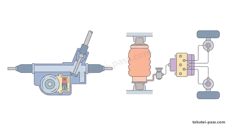
「電動式パワー・ステアリング(EPS)」は、運転者の操舵トルクや車速に応じてEPS・ECUが電動モータの電流を制御し、ステアリング操作力を補助(アシスト)する装置であり、据え切り時や低速走行時は大きな電流を流し、高速走行時は電流を減らして操縦安定性を高める。
'Electric Power Steering (EPS)' is a system in which the EPS-ECU controls electric motor current according to the driver's steering torque and vehicle speed to assist steering effort—supplying a large current during stationary or low-speed steering and reducing current at high speeds to enhance steering stability.
操舵トルクを検出する「ホールIC式トルク・センサ」では、ステアリング・ホイール側の「インプット・シャフト」とピニオン・ギヤ側の「アウトプット・シャフト」が細い「トーション・バー」を介して連結されている。
In a 'Hall-IC torque sensor' that detects steering torque, the 'input shaft' on the steering wheel side and the 'output shaft' on the pinion gear side are connected via a thin 'torsion bar'.
ここで「インプット・シャフトには多極磁石」が取り付けられ、「アウトプット・シャフトには磁気を集めるヨーク(軟磁性体リング)」が取り付けられている(取付位置が逆になっている選択肢は誤り)。
Here, a 'multi-pole magnet is mounted on the input shaft', and a 'magnetic yoke (soft magnetic ring) that collects magnetic flux is mounted on the output shaft' (options that reverse these mounting positions are incorrect).
ステアリング・ホイールを操作してトーション・バーに「ねじれ」が生じると、インプット・シャフト(多極磁石)とアウトプット・シャフト(ヨーク)の間に相対的な回転変位が生じる。
When the steering wheel is turned and the torsion bar twists, a relative rotational displacement occurs between the input shaft (multi-pole magnet) and the output shaft (yoke).
この変位によってヨークから磁気コレクタを経由して「ホールIC」を通過する磁束密度が変化し、ホールICは「操舵力(トルクの大きさ)と操舵方向(右・左)の両方」を電圧信号として検出する。
This displacement changes the magnetic flux density passing from the yoke through the magnetic collector to the 'Hall IC', allowing the Hall IC to detect 'both steering force (torque magnitude) and steering direction (left or right)' as voltage signals.
Key points
- ホールIC式トルク・センサは、「インプット・シャフトに多極磁石」、「アウトプット・シャフトにヨーク」が取り付けられている。
In a Hall-IC torque sensor, the 'multi-pole magnet is mounted on the input shaft' and the 'yoke is mounted on the output shaft'. - トーション・バーのねじれによる磁束変化から、「操舵力(大きさ)と操舵方向(左右)」の両方を検出する。
From magnetic flux changes caused by torsion bar twist, the sensor detects 'both steering force (magnitude) and steering direction (left/right)'. - 車速感応制御により、低速時はモータ電流を大きくして軽くし、高速時は電流を小さくして手応えを安定させる。
Through vehicle-speed-sensitive control, motor current is increased at low speeds for light steering and decreased at high speeds for stable road feel.
| Word | Meaning |
|---|---|
| 電動式パワー・ステアリング(EPS) | Electric Power Steering (EPS) |
| ホールIC式トルク・センサ | Hall-IC torque sensor |
| インプット・シャフト(多極磁石) | input shaft (multi-pole magnet) |
| アウトプット・シャフト(ヨーク)とトーション・バー | output shaft (yoke) and torsion bar |
ホイール・アライメント(キャンバ・キャスタ・キングピン傾角・トーイン)とサイド・スリップ
Wheel Alignment (Camber, Caster, Kingpin Inclination, Toe-In) and Side Slip
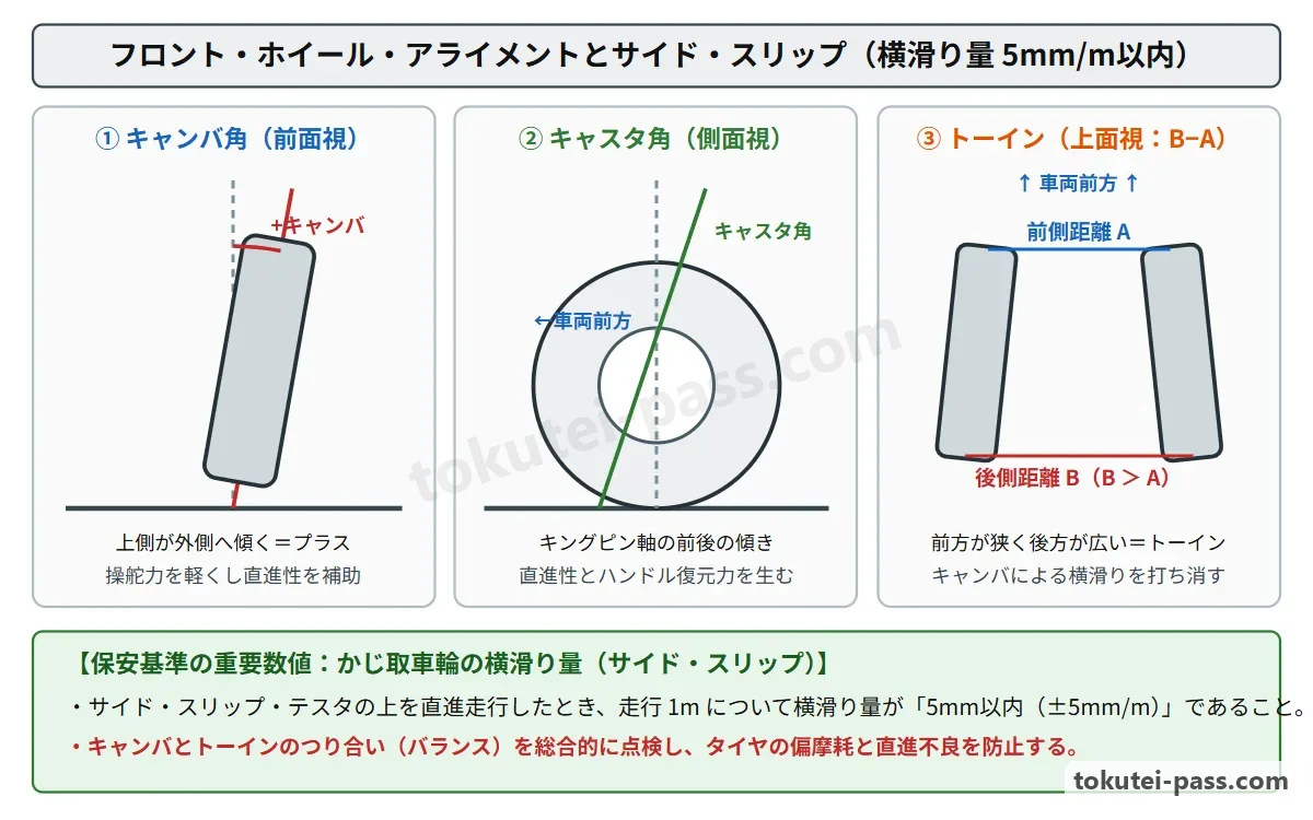
「ホイール・アライメント」とは車輪の整列状態をいい、前輪を前から見て上側が外側に傾く「プラス・キャンバ」や、操舵中心軸の上側が内側に傾く「キングピン傾角」は、路面での操舵抵抗(キングピン・オフセット)を減らしてハンドル操作力を軽減する。
'Wheel alignment' refers to the geometric arrangement of the wheels: 'positive camber' (where the top of the front wheels tilts outward when viewed from the front) and 'kingpin inclination' (where the top of the steering pivot axis tilts inward) reduce the kingpin offset (scrub radius) on the road surface to lighten steering effort.
また横から見てキングピン軸の上側が後方へ傾く「プラス・キャスタ」は、キャスタ・トレールを作り出して直進安定性と旋回後のハンドル復元力(セルフ・アライニング・トルク)を与える。
Meanwhile, 'positive caster' (where the top of the kingpin axis tilts rearward when viewed from the side) creates caster trail, providing straight-line stability and steering wheel return force after cornering (self-aligning torque).
上から見て左右前輪の前側の間隔(A)が後側の間隔(B)より狭くなっている状態を「トーイン(B − A)」といい、プラス・キャンバによってタイヤが外側へ転がろうとするキャンバ・スラストを打ち消して偏摩耗と横滑りを防ぐ。
Viewed from above, the condition where the front distance (A) between the left and right front tires is narrower than the rear distance (B) is called 'toe-in (B − A)', which cancels out camber thrust (the tendency of positively cambered tires to roll outward) to prevent uneven wear and side slip.
自動車が直進した際に前輪が横方向に滑る量を「サイド・スリップ量」といい、道路運送車両の保安基準では、サイド・スリップ・テスタで測定した際に「走行1mについてインまたはアウトに5mm以内」でなければならないと定められている。
The amount by which the front wheels slip sideways when the vehicle travels straight ahead is called 'side slip'; under the Road Transport Vehicle Safety Standards, when measured with a side-slip tester, it must be 'within 5 mm (inward or outward) per 1 m of travel'.
もしキャンバが変化しないままトーインが過大になると、タイヤは内側(イン側)へ横滑りし、トレッドの「外側」が羽根状に摩耗するフェザー・エッジ摩耗が生じる。
If toe-in becomes excessive while camber remains unchanged, the tires are dragged inward, causing featheredge wear where the 'outer' side of the tread wears in a feather-like pattern.
Key points
- トーインは上から見た左右輪の「後側間隔B − 前側間隔A」で求め、キャンバによる外側への横滑りを防ぐ。
Toe-in is calculated as 'Rear distance B − Front distance A' between left and right wheels viewed from above, preventing outward side slip caused by camber. - 保安基準におけるかじ取車輪のサイド・スリップ量は「走行1mについて(インまたはアウト)5mm以内」である。
Under the Safety Standards, the side slip of steered wheels must be 'within 5 mm (in or out) per 1 m of travel'. - キングピン傾角とキャンバはキングピン・オフセットを小さくして操舵力を軽減し、キャスタは直進性と復元性を高める。
Kingpin inclination and camber reduce kingpin offset to lighten steering effort, while caster improves straight-line stability and returnability. - 【例】前輪のタイヤ後側中心間隔Bが1,452mm、前側中心間隔Aが1,449mmのとき → トーイン = 1,452 − 1,449 = 3mm
Example: When rear center-to-center distance B of the front tires is 1,452mm and front center-to-center distance A is 1,449mm → Toe-in = 1,452 − 1,449 = 3mm - 【例】サイド・スリップ・テスタ上を1m走行したときの横滑り量がイン3.5mmのとき → 基準(5mm以内)を満たすため「良(適合)」
Example: When side slip measured over 1m of travel on a side-slip tester is IN 3.5mm → Meets the standard (within 5mm), so judged 'Good (Pass)'
| Word | Meaning |
|---|---|
| キャンバ・キャスタ・キングピン傾角 | camber, caster, kingpin inclination |
| トーイン(B − A) | toe-in (B − A) |
| サイド・スリップ量(走行1mにつき5mm以内) | side slip amount (within 5 mm per 1 m of travel) |
| セルフ・アライニング・トルク | self-aligning torque |
ブレーキの制動作用・停止距離計算・ブレーキ液とベーパー・ロック現象
Braking Action, Stopping Distance Calculation, Brake Fluid, and Vapor Lock
自動車の油圧式ブレーキ(制動装置)は、パスカルの原理によりマスタ・シリンダで発生させた油圧を各車輪へ伝え、パッドやライニングの摩擦によって走行中の自動車が持つ「運動エネルギを熱エネルギに変換」して減速・停止させる。
An automotive hydraulic brake system transmits hydraulic pressure generated in the master cylinder to each wheel according to Pascal's principle, using friction from pads or linings to 'convert the kinetic energy of the moving vehicle into heat energy' to decelerate and stop the vehicle.
運転者が危険を認知してから自動車が完全に停止するまでの「停止距離」は、ブレーキが効き始めるまでの「空走距離(空走時間×速度)」と、ブレーキが効き始めてから停止するまでの「制動距離」を足し合わせた距離である。
The 'stopping distance' from the moment the driver perceives danger until the vehicle comes to a complete halt equals the sum of the 'free-running (reaction) distance (reaction time × speed)' before the brakes begin to take effect and the 'braking distance' from when the brakes take effect until the vehicle stops.
路面との摩擦係数が一定のとき、空走距離は走行速度に比例するが、「制動距離は走行速度の2乗に比例して長くなる」(例えば速度が2倍になると制動距離は4倍になる)。
When the coefficient of friction with the road surface is constant, free-running distance is proportional to travel speed, whereas 'braking distance increases in proportion to the square of travel speed' (for example, doubling speed quadruples braking distance).
グリコール系ブレーキ液(DOT3・DOT4など)には「吸湿性(大気中の水分を吸収する性質)」があり、水分を吸収するほど「沸点が低下する」ため、定期的な交換が必要である。
Glycol-based brake fluid (such as DOT3 and DOT4) is 'hygroscopic (absorbs moisture from the atmosphere)'; the more moisture it absorbs, the lower its 'boiling point drops', requiring periodic replacement.
降坂時にフット・ブレーキを多用してブレーキ液が沸騰し、配管内に気泡が生じてペダルを踏んでも油圧が伝わらなくなる現象を「ベーパー・ロック現象」といい、摩擦材自体の過熱で摩擦係数が低下する「フェード現象」と区別する。
When descending a long grade and overusing the foot brake causes the brake fluid to boil and form vapor bubbles in the lines—so stepping on the pedal fails to transmit hydraulic pressure—it is called 'vapor lock', which must be distinguished from 'fade', where overheating of the friction material itself lowers its friction coefficient.
Key points
- ブレーキは摩擦によって自動車の「運動エネルギを熱エネルギに変換」して減速させる。
Brakes decelerate a vehicle by using friction to 'convert kinetic energy into heat energy'. - 停止距離 = 空走距離 + 制動距離であり、制動距離は「走行速度の2乗」に比例する。
Stopping distance = Free-running distance + Braking distance, and braking distance is proportional to the 'square of travel speed'. - ブレーキ液は水分を吸収すると沸点が低下し、液が沸騰して気泡ができ制動力を失う現象を「ベーパー・ロック現象」という。
Brake fluid boiling point drops when it absorbs moisture; the loss of braking force due to boiling fluid forming vapor bubbles is called 'vapor lock'. - 【例】空走距離が15m、制動距離が25mのときの停止距離 → 15 + 25 = 40m
Example: When free-running distance is 15m and braking distance is 25m, stopping distance → 15 + 25 = 40m - 【例】時速36km/h(秒速10m/s)で空走時間が1.0秒、制動距離が8mのとき → 空走距離 = 10 × 1.0 = 10m、停止距離 = 10 + 8 = 18m
Example: At 36km/h (10m/s) with a reaction time of 1.0s and braking distance of 8m → Free-running distance = 10 × 1.0 = 10m; Stopping distance = 10 + 8 = 18m
| Word | Meaning |
|---|---|
| 運動エネルギと熱エネルギ | kinetic energy and heat energy |
| 停止距離・空走距離・制動距離 | stopping distance, free-running distance, and braking distance |
| ベーパー・ロック現象とフェード現象 | vapor lock phenomenon and fade phenomenon |
| グリコール系ブレーキ液(吸湿性) | glycol-based brake fluid (hygroscopic property) |
ABS(アンチロック・ブレーキ・システム)と横滑り防止装置(ESC)
ABS (Anti-Lock Brake System) and Electronic Stability Control (ESC)
「ABS(アンチロック・ブレーキ・システム)」は、急制動時や滑りやすい路面での制動時に各車輪の回転速度を監視し、ホイール・シリンダ油圧を「減圧・保持・増圧」することで車輪のロックを防ぎ、車両の方向安定性とハンドル操舵性を確保する。
'ABS (Anti-lock Brake System)' monitors the rotational speed of each wheel during sudden braking or braking on slippery surfaces and controls wheel cylinder pressure through 'pressure decrease, hold, and increase' to prevent wheel lock, ensuring directional stability and steerability.
ABSには「フェイルセーフ機能」が備わっており、万一ABSの電気系統に異常が発生した場合は、ABS警告灯を点灯させるとともに「ABSの制御を停止し、通常のブレーキ(サービス・ブレーキ)として問題なく作動させる」。
ABS is equipped with a 'fail-safe function': in the event an electrical fault occurs in the ABS system, it illuminates the ABS warning lamp, 'stops ABS control, and allows the brakes to operate normally as ordinary service brakes'.
またエンジン始動直後の発進時には、ABS・ECUがソレノイド・バルブやポンプ・モータの電気的な初期点検(イニシャル・チェック)を行うため、「ハイドロリック・ユニットから一時的に作動音が発生することがある」が正常である。
Immediately after starting the engine and pulling away, the ABS-ECU performs an initial electrical check of the solenoid valves and pump motor, so 'the hydraulic unit may temporarily produce an operating sound', which is normal.
なお、完全に放電したバッテリをブースタ・ケーブルで接続して始動し、充電が不十分なまま直ちに走行すると、電源電圧低下を検知してABS警告灯が点灯することがある。
Note that if a completely discharged battery is jump-started with booster cables and the vehicle is driven immediately before charging is sufficient, the ABS warning lamp may illuminate due to low power supply voltage detection.
ABS警告灯の点滅によりダイアグノーシス・コードを読み取る際、2つ以上の異常コードがあるときは、発生順ではなく「コード番号の小さい順」に表示される点に注意する。
When reading diagnostic trouble codes via the blinking of the ABS warning lamp, if two or more trouble codes are stored, they are displayed in 'ascending order from the smallest code number' rather than in the chronological order in which they occurred.
Key points
- ABSのフェイルセーフ機能は、電気系異常時に「ABS制御を停止し、通常のブレーキとして作動させる」。
The ABS fail-safe function 'stops ABS control and operates the brakes as normal service brakes' when an electrical fault occurs. - エンジン始動後のイニシャル・チェック時に作動音がすることや、ブースタ・ケーブル始動直後の電圧不足でABS警告灯が点灯することがある。
An operating sound may occur during the initial check after engine start, and the ABS warning lamp may light up due to low voltage immediately after jump-starting. - ABS警告灯点滅による複数の故障コード表示は、「コード番号の小さい順」に出力される(発生した順という記述は誤り)。
When multiple trouble codes are displayed by blinking the ABS warning lamp, they are output in 'order from the smallest code number' (claiming order of occurrence is incorrect).
| Word | Meaning |
|---|---|
| アンチロック・ブレーキ・システム(ABS) | Anti-lock Brake System (ABS) |
| 減圧・保持・増圧制御 | pressure decrease, hold, and increase control |
| イニシャル・チェックとフェイルセーフ機能 | initial check and fail-safe function |
| 横滑り防止装置(ESC) | Electronic Stability Control (ESC) |
試験によく出るポイントと覚え方
Common Exam Points and How to Remember Them
シャシ分野(走行・操縦・制動)の2号学科試験では、タイヤのばね定数、エア・スプリング、EPSのトルク・センサ、ホイール・アライメント、およびABSの5項目が頻出である。
In the chassis section (running, steering, braking) of the Type 2 written exam, five topics appear frequently: tire spring constant, air springs, EPS torque sensors, wheel alignment, and ABS.
タイヤとサスペンションでは、「静的縦ばね定数(N/mm)=小さいほど柔らかく乗り心地が良い」「静荷重半径=路面から車軸中心までの垂直距離」「エア・スプリング=荷重が増えるとばね定数も大きくなり固有振動数が一定」と覚えよう。
For tires and suspension, memorize: 'Static vertical spring constant (N/mm) = smaller value means softer and better ride comfort', 'Static loaded radius = vertical distance from road surface to axle center', 'Air spring = as load increases, spring constant increases so natural frequency stays constant'.
ステアリングとアライメントでは、「ホールIC式トルク・センサ=インプット・シャフトに多極磁石、アウトプット・シャフトにヨーク(操舵力と方向の両方を検出)」「トーイン=B − A」「サイド・スリップ保安基準=走行1mにつき5mm以内」を確実に押さえる。
For steering and alignment, lock in: 'Hall-IC torque sensor = multi-pole magnet on input shaft, yoke on output shaft (detects both force and direction)', 'Toe-in = B − A', 'Side slip safety standard = within 5 mm per 1 m of travel'.
ブレーキとABSでは、「停止距離=空走距離+制動距離(運動エネルギ→熱エネルギ)」「ABS故障時=通常のブレーキとして作動」「ABS警告灯の故障コード点滅=コード番号の小さい順(発生順は誤り)」が鉄板のポイントである。
For brakes and ABS: 'Stopping distance = Free-running distance + Braking distance (kinetic energy → heat energy)', 'On ABS fault = operates as normal brakes', 'ABS warning lamp blinking multiple codes = displayed in ascending order from smallest code number (order of occurrence is false)'.
Key points
- タイヤ:静的縦ばね定数(N/mm)は「小さいほど」乗り心地が良い。エア・スプリングは荷重に応じてばね定数が変化し固有振動数を一定に保つ。
Tires & suspension: A 'smaller' static vertical spring constant (N/mm) gives better ride comfort; air springs vary spring constant with load to keep natural frequency constant. - EPSトルク・センサ:「インプット・シャフトに多極磁石」「アウトプット・シャフトにヨーク」が付き、操舵力と方向を検出する。
EPS torque sensor: 'Multi-pole magnet on input shaft' and 'yoke on output shaft' detect both steering force and direction. - アライメント・ブレーキ:サイド・スリップは「走行1mにつき5mm以内」、停止距離=空走距離+制動距離。
Alignment & brakes: Side slip must be 'within 5 mm per 1 m of travel'; Stopping distance = Free-running distance + Braking distance. - ABS:異常時は通常ブレーキになり、警告灯点滅の複数コードは「番号の小さい順」に表示される。
ABS: reverts to normal brakes during a fault; multiple blinking trouble codes are displayed in 'order from the smallest code number'.
| Word | Meaning |
|---|---|
| 静的縦ばね定数と固有振動数 | static vertical spring constant and natural frequency |
| 多極磁石とヨーク | multi-pole magnet and yoke |
| サイド・スリップ(5mm以内) | side slip (within 5 mm) |
| ABSフェイルセーフとコード表示順 | ABS fail-safe and trouble code display order |
Running Gear, Steering & Brakes
Practice this chapter in the appOfficial references
- 国土交通省「自動車整備分野特定技能2号評価試験実施要領」および日本自動車整備振興会連合会(JASPA)学科試験サンプル問題 — https://www.mlit.go.jp/jidosha/jidosha_fr10_000041.html