
Inspection, Disassembly, Assembly, Adjustment, and Repair
点検・分解・組立て・調整・修理
Automobile Maintenance · 自動車整備分野 · Written by Tokutei Pass based on the official study texts; not copied verbatim.
日常点検(15項目)と定期点検の基本
Daily Inspection (15 Items) and Periodic Inspection Basics
自動車の安全走行と公害防止のため、道路運送車両法によって「日常点検」と「定期点検」が義務付けられています。自家用乗用車の日常点検は「15項目」あり、走行距離や運行時の状態から判断して適切な時期(長距離走行前など)に行います(事業用自動車やレンタカーは毎日1回、運行前に実施します)。
To ensure safe driving and prevent pollution, the Road Transport Vehicle Act mandates Daily Inspection and Periodic Inspection. Daily inspection for private passenger cars consists of 15 items, carried out at appropriate times judged from mileage and operating conditions, such as before a long drive (commercial vehicles and rental cars must be inspected once every day before operation).
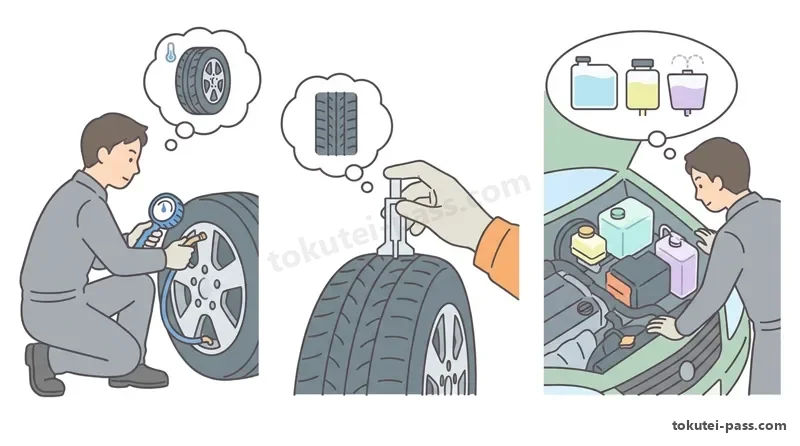
① エンジン・ルームを見て点検する5項目は、「ウインド・ウォッシャ液の量」「ブレーキ液の量」「バッテリ液の量」「冷却水(リザーバ・タンク)の量」「エンジン・オイルの量」です。
(1) The 5 items inspected by looking inside the engine compartment are: Window washer fluid level, Brake fluid level, Battery electrolyte level, Coolant level (in the reservoir tank), and Engine oil level.
オイル・レベル・ゲージは一度抜いてウエスで拭き取り、再び奥まで差し込んでから抜き取り、油面が上限(F/MAX)と下限(L/MIN)の間にあるか確認します。
Pull out the engine oil dipstick (oil level gauge) once, wipe it clean with a rag, insert it all the way back in, and pull it out again to check that the oil level is between the upper limit (F/MAX) and lower limit (L/MIN).
② 車の周りを回って点検する4項目は、「タイヤの空気圧」「タイヤの亀裂・損傷の有無」「タイヤの溝の深さ(異常な摩耗)」「ランプ類の点灯・点滅および汚れ・損傷」です。
(2) The 4 items inspected by walking around the vehicle are: Tire inflation pressure, Presence of tire cracks or damage, Tire tread depth (abnormal wear), and Lighting / flashing, dirt, or damage of lamps.
③ 運転席に座って点検する6項目は、「ブレーキ・ペダルの踏みしろとブレーキの効き」「パーキング・ブレーキ・レバーの引きしろ(踏みしろ)」「ウインド・ウォッシャの噴射状態」「ワイパの拭き取り状態」「エンジンの掛かり具合・異音」「エンジンの低速および加速の状態」です。
(3) The 6 items inspected while sitting in the driver's seat are: Brake pedal clearance when depressed and braking effectiveness, Parking brake lever pull (or pedal) stroke, Window washer spray condition, Wiper wiping condition, Engine starting condition and abnormal noise, and Engine low-speed and acceleration condition.
また、自家用乗用車の定期点検には1年ごと(12ヶ月点検)と2年ごと(24ヶ月点検)があります。
Furthermore, periodic inspections for private passenger cars include the 1-year inspection (12-month inspection) and the 2-year inspection (24-month inspection).
Key points
- 日常点検15項目は、エンジン・ルーム5項目(各種液量)、車の周り4項目(タイヤ3項目+ランプ類)、運転席6項目(ブレーキ・視界・エンジン調子)で構成される
The 15 daily inspection items consist of 5 engine room items (fluid levels), 4 walk-around items (3 tire items + lamps), and 6 driver's seat items (brakes, visibility, engine condition) - エンジン・オイル量は、エンジン停止後にレベル・ゲージを1回拭いてから奥まで差し込み、上限と下限の間にあるか点検する
Check engine oil level with the engine stopped by wiping the dipstick once, inserting it fully, and verifying the level is between the upper and lower marks - 自家用乗用車の定期点検は1年(12ヶ月)ごとと2年(24ヶ月)ごとに実施される
Periodic inspections for private passenger cars are conducted every 1 year (12 months) and every 2 years (24 months)
| Word | Meaning |
|---|---|
| 日常点検(15項目) | Daily inspection (15 items) (Mandatory pre-operation / routine check covering 5 engine room, 4 exterior, and 6 cabin items) |
| 定期点検(12ヶ月・24ヶ月点検) | Periodic inspection (12-month and 24-month inspection) (Statutory regular maintenance inspections conducted every 1 and 2 years) |
| オイル・レベル・ゲージ(oil level gauge) | Oil level gauge (dipstick) (Rod used to check that engine oil level sits between L/MIN and F/MAX) |
| リザーバ・タンク(reservoir tank) | Reservoir tank (Translucent tank allowing visual inspection of coolant or brake fluid level) |
分解・組立ての基本ルールと非再使用部品
Basic Rules of Disassembly / Assembly and Non-Reusable Parts
エンジンやシャシ部品を分解するときは、組み立て時に元の位置や向き、回転バランスが狂わないよう、分解前に「合いマーク(合マーク)」を確認するか新しく付けておきます。また、取り外したピストンやバルブ、ベアリングなどは気筒番号順に整理して並べ、混ざらないように保管します。
When disassembling engine or chassis parts, check existing mating marks (alignment marks) or make new ones before disassembly so that original positions, orientations, and rotational balance are not lost during reassembly. Also, arrange removed pistons, valves, and bearings in cylinder-number order so they do not get mixed up.
一度分解して取り外したら、たとえ外観に傷がなくても再び使わず必ず新品と交換しなければならない部品を「非再使用部品(再使用不可部品)」といいます。代表例は、ガスケット、パッキン、Oリング、オイル・シールなどのシール部品と、割りピン(コッタ・ピン)、爪付きロック・ワッシャなどの緩み止め部品です。
Parts that must never be reused once disassembled and removed—and must always be replaced with new ones even if they look undamaged—are called non-reusable parts. Typical examples include sealing parts such as gaskets, packings, O-rings, and oil seals, as well as locking parts such as cotter pins (split pins) and clawed lock washers.
Oリングやオイル・シールを新品に組み付ける際は、リップ部(密着部)がねじれたり傷ついたりしないよう、リップ部にエンジン・オイルや指定グリースを薄く塗ってからまっすぐ圧入します。
When installing a new O-ring or oil seal, apply a thin coat of engine oil or specified grease to the lip (sealing edge) and press it in straight so the lip is not twisted or damaged.
また、キャッスル・ナット(溝付きナット)に新品の割りピンを通すときは、規定トルクで締めたあと、ピン穴が合わない場合は「さらに締め込む方向」へ回して穴を合わせます(緩める方向へ戻してはなりません)。
Furthermore, when inserting a new cotter pin into a castle nut (slotted nut), after tightening to the specified torque, if the pin slots do not align with the bolt hole, turn the nut further in the tightening direction to align them (never back it off in the loosening direction).
組み立て前には、すべての部品を洗浄して圧縮空気(エア・ブロー)でオイル通路のゴミを吹き飛ばし、ピストンやシリンダ、軸受などの摺動部(こすれ合う面)には初期かじり(焼き付き)を防ぐため、必ず新しいエンジン・オイルを塗布してから組み付けます。
Before assembly, clean all parts, blow out dust from oil passages with compressed air (air blow), and always apply fresh engine oil to sliding surfaces—such as pistons, cylinders, and bearings—before assembly to prevent initial scuffing or seizure.
Key points
- 分解前には組付け位置やバランスが狂わないよう「合いマーク」を付け、外した部品は気筒順に整理して並べる
Before disassembly, place mating marks so installation position and balance are preserved, and organize removed parts in cylinder order - ガスケット、パッキン、Oリング、オイル・シール、割りピン(コッタ・ピン)は「非再使用部品」であり、分解時は必ず新品と交換する
Gaskets, packings, O-rings, oil seals, and cotter pins are non-reusable parts and must always be replaced with new ones upon disassembly - 摺動部やOリング・オイル・シールのリップ部には、傷つきや初期焼き付きを防ぐためオイルやグリースを塗ってから組み付ける
Apply oil or grease to sliding parts and the lips of O-rings and oil seals before assembly to prevent damage and initial seizure
| Word | Meaning |
|---|---|
| 合いマーク(mating mark) | Mating mark (alignment mark) (Reference mark placed prior to disassembly to ensure exact reassembly alignment) |
| 非再使用部品(ガスケット・Oリング・割りピン) | Non-reusable parts (gaskets, O-rings, cotter pins) (Single-use components that must always be replaced with new parts when removed) |
| オイル・シール(oil seal) | Oil seal (Rotary shaft seal whose lip must be lubricated before installation) |
| キャッスル・ナット(溝付きナット) | Castle nut (slotted nut) (Nut with slots secured against loosening by passing a new cotter pin through) |
重要ボルト・ナットの締付け順序(シリンダ・ヘッド/ホイール)
Tightening Sequence of Critical Bolts and Nuts (Cylinder Head / Wheels)
シリンダ・ヘッドのように広い面を多数のボルトで締め付ける部品では、ボルトを緩める順序や締め付ける順序を誤ると、シリンダ・ヘッドに「ひずみ(変形)」が生じてガス漏れや水漏れの原因になります。
For components where a wide surface is fastened by many bolts, such as a cylinder head, using the wrong loosening or tightening sequence causes cylinder head warpage (distortion), resulting in gas or water leaks.
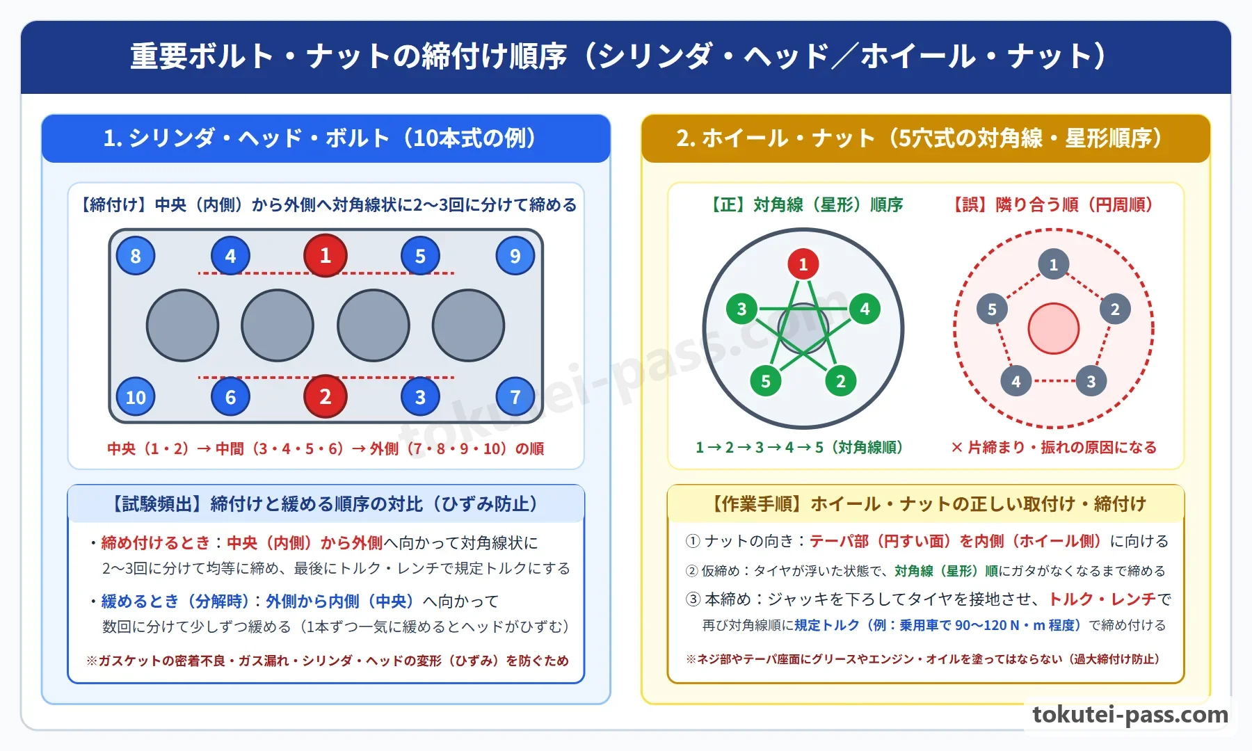
シリンダ・ヘッド・ボルトを「締め付けるとき(組付け時)」は、必ず「中央(内側)から外側」へ向かって対角線状に順番に、2〜3回に分けて少しずつ均等に締め、最後にトルク・レンチ(または角度締め)で規定トルクに仕上げます。
When tightening cylinder head bolts (during assembly), always work from the center (inside) toward the outside in a diagonal criss-cross pattern, tightening evenly a little at a time in 2 to 3 stages, and finish to the specified torque with a torque wrench (or angle tightening).
逆に、シリンダ・ヘッド・ボルトを「緩めるとき(分解時)」は、締め付けるときとは反対に「外側から内側(中央)」へ向かって、数回に分けて少しずつ緩めます。1本ずつ一気に緩めたり、内側から緩めたりしてはなりません。
Conversely, when loosening cylinder head bolts (during disassembly), work in the opposite order—from the outside toward the inside (center)—loosening gradually in several stages. Never loosen one bolt completely at a time or loosen from the inside out.
また、タイヤ(ディスク・ホイール)を取り付けるときの「ホイール・ナット」は、テーパ部(円すい状に斜めになった面)を必ず「内側(ホイール側)」に向けます。
Additionally, when mounting a tire (disc wheel), orient the wheel nuts so the tapered (cone-shaped) seat faces inward (toward the wheel).
そして隣り合う順ではなく「対角線(星形)の順序」で2〜3回に分けて仮締めし、タイヤを接地させてからトルク・レンチで規定トルクに本締めします(ネジ部にオイルやグリースを塗ると過大締付けになるため原則塗布しません)。
Rather than tightening adjacent nuts in a circle, snug-tighten them in 2 to 3 stages in a diagonal (star) pattern, lower the tire to the ground, and perform final tightening to the specified torque with a torque wrench (in principle, do not apply oil or grease to the threads as it causes over-torquing).
Key points
- シリンダ・ヘッド・ボルトを「締め付けるとき」は「中央(内側)から外側」の順に2〜3回に分けて均等に締める
When tightening cylinder head bolts, tighten evenly in 2 to 3 stages in order from the center (inside) toward the outside - シリンダ・ヘッド・ボルトを「緩めるとき(分解時)」は逆に「外側から内側(中央)」の順に数回に分けて緩める
When loosening cylinder head bolts (disassembly), work in reverse from the outside toward the inside (center) in several stages - ホイール・ナットはテーパ部を内側(ホイール側)に向け、「対角線(星形)の順序」で締め付けて最後にトルク・レンチで規定トルクにする
Orient wheel nuts with the tapered portion facing inward (wheel side), tighten in a diagonal (star) sequence, and finish to specified torque with a torque wrench
| Word | Meaning |
|---|---|
| シリンダ・ヘッド・ボルト | Cylinder head bolt (Tighten from center outward; loosen from outside inward) |
| ひずみ(変形)防止 | Warpage (distortion) prevention (Reason for multi-stage symmetrical loosening and tightening sequences) |
| ホイール・ナット(テーパ部) | Wheel nut (tapered seat) (Conical seat of the lug nut that centers the wheel; must face inward) |
| 対角線(星形)順序 | Diagonal (star) sequence (Criss-cross tightening order used on wheels and multi-bolt flanges) |
調整作業とブレーキのエア抜き・オイル交換手順
Adjustment Work, Brake Air Bleeding, and Oil Change Procedures
エンジンのバルブ・クリアランス(バルブすき間)を調整するときは、まずクランク・プーリを回して第1気筒のピストンを「圧縮上死点」に合わせ、その位置でロッカ・アームがフリーになっているバルブのすき間をシックネス・ゲージで測定・調整します。
When adjusting engine valve clearance, first turn the crankshaft pulley to set the #1 cylinder piston at top dead center (TDC) on the compression stroke, and use a thickness gauge to measure and adjust the valves whose rocker arms are free at that position.
次にクランクシャフトを「1回転(360°)」回して第4気筒(4気筒車の場合)を圧縮上死点に合わせ、残りのバルブを調整します。
Next, rotate the crankshaft 1 full turn (360 degrees) to set the #4 cylinder (in a 4-cylinder engine) at compression TDC, and adjust the remaining valves.
エンジン・オイルとオイル・フィルタを交換するときは、ドレン・プラグから古いオイルを抜いたあと、新しいドレン・ガスケット(パッキン)に交換してドレン・プラグを締めます。
When changing engine oil and the oil filter, after draining old oil from the drain plug, replace the drain gasket (washer) with a new one and tighten the drain plug.
新しいオイル・フィルタを取り付ける際は、Oリングに新しいエンジン・オイルを薄く塗り、取付面に当たるまで手で回し入れてから指定回転数(または規定トルク)で締め付けます。
When installing a new oil filter, apply a thin coat of clean engine oil to the O-ring, screw the filter in by hand until the seal contacts the mounting surface, and then tighten it by the specified number of turns (or specified torque).
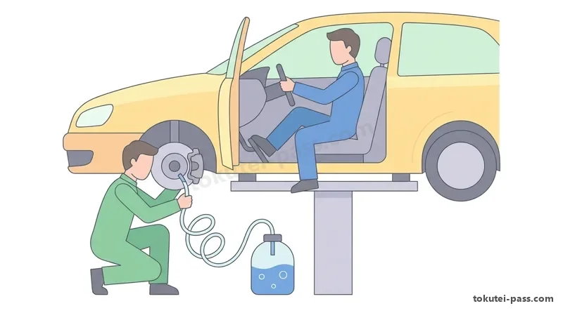
油圧ブレーキの配管やシリンダを分解したあとは、配管内に入った空気(エア)を抜く「エア抜き(ブリーディング)作業」が必ず必要です。リザーバ・タンクにブレーキ液を補充し、原則としてマスタ・シリンダから「最も遠い車輪」のブリーダ・プラグから順に行います。
After disassembling hydraulic brake lines or cylinders, air bleeding (bleeding the brakes) is always required to expel air that entered the lines. Top up brake fluid in the reservoir tank, and in principle start from the bleeder plug of the wheel cylinder farthest from the master cylinder.
エア抜きは2人1組で行います。1人がブレーキ・ペダルを数回踏んでから強く踏み続けた状態で、もう1人がブリーダ・プラグを緩めてビニル・ホースから気泡混じりのブレーキ液を排出させ、ペダルを踏み切ったままブリーダ・プラグを「締めてから」ペダルを戻します。これを気泡が出なくなるまで繰り返します。
Air bleeding is performed by a two-person team. While one person pumps the brake pedal several times and holds it firmly depressed, the other person loosens the bleeder plug to let bubbly brake fluid escape through a vinyl hose, then tightens the bleeder plug while the pedal is still held down before letting the pedal return. Repeat this until no air bubbles appear.
Key points
- 4気筒エンジンのバルブ・クリアランス調整は、第1気筒を圧縮上死点に合わせて半数のバルブを調整し、クランクシャフトを1回転(360°)させて残りを調整する
To adjust valve clearance on a 4-cylinder engine, set cylinder #1 to compression TDC to adjust half the valves, then turn the crankshaft 1 revolution (360 degrees) to adjust the rest - オイル・フィルタ交換時は、新品フィルタのOリングにエンジン・オイルを塗ってから組み付け、エンジン始動後に油漏れがないか確認する
When replacing the oil filter, coat the new filter's O-ring with engine oil before installation, and check for oil leaks after starting the engine - ブレーキのエア抜き作業は、リザーバ・タンクの液切れに注意しながら、ペダルを踏み込んだ状態でブリーダ・プラグを緩め、プラグを締めてからペダルを戻す動作を気泡が消えるまで繰り返す
During brake air bleeding, watch the reservoir fluid level so it does not run dry, loosen the bleeder plug with the pedal held down, and tighten the plug before releasing the pedal until bubbles stop
| Word | Meaning |
|---|---|
| 圧縮上死点 | Top dead center (TDC) on compression stroke (Piston position where both intake and exhaust valves are closed for valve adjustment) |
| ドレン・ガスケット(drain gasket) | Drain gasket (Sealing washer on the oil pan drain plug that should be replaced at oil changes) |
| エア抜き(air bleeding) | Air bleeding (brake bleeding) (Procedure for purging trapped air bubbles from hydraulic brake lines) |
| ブリーダ・プラグ(bleeder plug) | Bleeder plug (bleeder screw) (Valve on a wheel cylinder or caliper opened to expel air and fluid) |
基準値と使用限度(限度値)の合否判定と計算
Pass / Fail Judgment and Calculations Using Standard Values and Service Limits
実技試験の「判断等試験」や「計画立案等試験」では、計量器で測定した値(測定値)を整備解説書の「基準値」および「使用限度(限度値)」と比較し、その部品が良好(合格・そのまま使える)か、不良(不合格・修理または交換が必要)かを判定する問題が必ず出題されます。
In the judgment and planning sections of the practical exam, questions always require comparing a measured value against the service manual's standard value and service limit (limit value) to determine whether a part is Good (Pass: reusable as-is) or Defective (Fail: requires repair or replacement).
第1のパターンは、摩耗すると厚さや深さが「減る(小さくなる)」部品です。
Pattern 1 covers parts whose thickness or depth decreases (gets smaller) as they wear.
ブレーキ・パッドの厚さ、ブレーキシュー・ライニングの厚さ、ブレーキ・ディスク・ロータの厚さ、タイヤの溝の深さ、エンジンの圧縮圧力、バッテリ比重などは、使用限度が「下限(これ以上なければならない値)」として定められています。したがって「測定値 < 使用限度」なら不良(交換)です。
For brake pad thickness, brake shoe lining thickness, brake disc rotor thickness, tire tread depth, engine compression pressure, and battery specific gravity, the service limit is defined as a lower limit (minimum allowable value). Therefore, if Measured value < Service limit, the part is judged Defective (replace).
第2のパターンは、摩耗や変形によってすき間や振れが「増える(大きくなる)」部品です。
Pattern 2 covers parts whose clearance or runout increases (gets larger) due to wear or deformation.
シリンダ内径、ピストン・リング合口すき間、オイル・クリアランス、シャフトの曲がり、ディスク・ロータの振れ、シリンダ・ヘッドの平面度(ひずみ)、ブレーキ・ドラムの内径などは、使用限度が「上限(これ以下でなければならない値)」です。したがって「測定値 > 使用限度」なら不良(交換)です。
For cylinder bore diameter, piston ring end gap, oil clearance, shaft bend, disc rotor runout, cylinder head warpage, and brake drum inside diameter, the service limit is defined as an upper limit (maximum allowable value). Therefore, if Measured value > Service limit, the part is judged Defective (replace).
また、バルブ・クリアランスやファン・ベルトのたわみ量、ペダルの遊び、トーイン、アイドリング回転数のように「基準値の範囲(例:0.15〜0.25 mm)」が定められている項目は、測定値が範囲から外れていれば「調整が必要」と判定します。
Furthermore, for items specified by a standard value range (e.g., 0.15~0.25 mm) such as valve clearance, fan belt deflection, pedal free play, toe-in, and idling speed, if the measured value falls outside the range, judge that adjustment is required.
Key points
- ブレーキ・パッド厚さ、ディスク厚さ、タイヤ溝深さなどは摩耗すると小さくなるため、「測定値 < 使用限度(下限)」のときに交換(不良)と判定する
Because brake pad thickness, disc thickness, and tire tread depth decrease with wear, judge Replace (Defective) when Measured value < Service limit (lower limit) - ブレーキ・ドラム内径、シャフトの曲がり、ディスクの振れ、ヘッドのひずみ、オイル・クリアランスなどは、「測定値 > 使用限度(上限)」のときに交換(不良)と判定する
For brake drum inside diameter, shaft bend, disc runout, head warpage, and oil clearance, judge Replace (Defective) when Measured value > Service limit (upper limit) - 【例】ブレーキ・パッドの厚さの基準値が 10.0 mm、使用限度が 2.0 mm のとき、ノギスでの測定値が 1.5 mm であれば、使用限度(2.0 mm)を下回っているため「不良(パッド交換)」と判定する
Example: When brake pad standard thickness is 10.0 mm and the service limit is 2.0 mm, a vernier caliper reading of 1.5 mm is below the service limit (2.0 mm), so judge Defective (replace pad) - 【例】シャフトの曲がりの使用限度が 0.03 mm のとき、Vブロック上で1回転させたダイヤル・ゲージの振れが 0.08 mm だった場合、曲がり = 0.08 ÷ 2 = 0.04 mm となり、使用限度(0.03 mm)を超えるため「不良(交換)」となる
Example: When the shaft bend service limit is 0.03 mm and dial gauge runout over 1 turn on V-blocks is 0.08 mm, bend = 0.08 / 2 = 0.04 mm, which exceeds the limit (0.03 mm), so judge Defective (replace)
| Word | Meaning |
|---|---|
| 基準値(standard value) | Standard value (Nominal specification of a new or properly adjusted component) |
| 使用限度(service limit) | Service limit (wear limit) (Maximum or minimum permissible threshold before repair or replacement is required) |
| 摩耗量 | Wear amount (Difference between the original standard dimension and the measured dimension) |
| 合否判定 | Pass / fail judgment (Evaluating whether a measured value satisfies the service limit) |
故障原因の探究(トラブルシューティング)の基本
Fundamentals of Troubleshooting (Fault Diagnosis)
実技試験や現場での故障診断では、症状から考えられる原因を順序立てて絞り込みます。たとえば「スタータが全く回らない」場合は、まずバッテリ上がり(端子電圧・比重低下)、バッテリ・ターミナルの緩みや腐食、AT車のインヒビタ・スイッチ(P・Nレンジ以外に入っている)、またはスタータ本体の不良を点検します。
In the practical exam and shop troubleshooting, possible causes are narrowed down systematically from symptoms. For example, if the starter does not crank at all, inspect for a dead battery (low terminal voltage or specific gravity), loose or corroded battery terminals, the AT inhibitor switch (shift lever not in P or N), or a faulty starter motor.
「スタータは元気よく回るがエンジンが始動しない」場合は、エンジンの3大要素である「良い混合気(燃料)」「良い圧縮」「良い火花(点火)」の順に確認します。燃料切れやフューエル・ポンプの不作動、スパーク・プラグの火花飛び、タイミング・ベルト切れによる圧縮不良などを調べます。
If the starter cranks briskly but the engine does not start, check the three essential elements of an engine in order: Good air-fuel mixture (fuel), Good compression, and Good spark (ignition). Check for an empty fuel tank, inoperative fuel pump, spark plug firing, or loss of compression due to a broken timing belt.
「エンジンがオーバーヒートする」場合は、冷却水(LLC)の漏れ・不足、ファン・ベルトの緩みや切れ、サーモスタットが閉じたまま固着している不良、電動ファンの不作動、ラジエータ・コアの詰まり、またはラジエータ・キャップのプレッシャ・バルブ不良を点検します。
If the engine overheats, check for coolant (LLC) leakage or shortage, loose or broken fan belt, thermostat stuck closed, inoperative electric cooling fan, clogged radiator core, or faulty radiator cap pressure valve.
「ブレーキの効きが悪い・ペダルが深く入る」場合は、ブレーキ液漏れ、ブレーキ配管へのエア混入、ブレーキ・パッドやライニングの摩耗、または下り坂でのフェード現象・ベーパ・ロック現象を疑います。
If braking is poor or the brake pedal goes down too far, suspect brake fluid leakage, air trapped in the brake lines, worn brake pads or linings, or fade / vapor lock on a long downgrade.
また、車載式故障診断装置(OBD)に外部診断機(スキャン・ツール)をつなぐことで、ECUに記憶されたダイアグノーシス・コード(DTC:故障コード)を読み取ることができます。
In addition, connecting an external diagnostic tester (scan tool) to the on-board diagnostic system (OBD) allows reading diagnostic trouble codes (DTCs) stored in the ECU.
Key points
- スタータが回らないときはバッテリ電圧・端子の緩み・インヒビタ・スイッチを点検し、スタータが回るが始動しないときは「燃料・点火・圧縮」の3要素を点検する
If the starter does not crank, check battery voltage, loose terminals, and the inhibitor switch; if it cranks but will not start, check the 3 elements: Fuel, Ignition, and Compression - オーバーヒートの主な原因は、冷却水不足、ファン・ベルトの緩み・切れ、サーモスタットの閉固着、電動ファン不良などである
Major causes of overheating include insufficient coolant, loose or broken fan belt, thermostat stuck closed, and faulty electric fan - スキャン・ツール(外部診断機)を車両のDLC(データ・リンク・コネクタ)に接続すると、ECUが検知した故障コード(DTC)の読み取りや消去ができる
Connecting a scan tool (external diagnostic tester) to the vehicle's DLC (data link connector) enables reading and clearing diagnostic trouble codes (DTCs) detected by the ECU
| Word | Meaning |
|---|---|
| インヒビタ・スイッチ(inhibitor switch) | Inhibitor switch (Safety switch on AT vehicles that permits starter operation only in P or N) |
| オーバーヒート(overheat) | Overheat (Abnormal rise in engine temperature caused by cooling system failure) |
| スキャン・ツール(外部診断機) | Scan tool (external diagnostic tester) (Handheld tester plugged into the DLC to read ECU fault codes and live data) |
| ダイアグノーシス・コード(DTC:故障コード) | Diagnostic trouble code (DTC) (Malfunction code recorded by the ECU when a sensor or actuator fault occurs) |
自動車整備分野 特定技能1号評価試験のしくみと合格基準
Structure and Passing Criteria of the Specified Skilled Worker (i) Auto Maintenance Exam
「自動車整備分野特定技能1号評価試験」は、日本の自動車整備工場において、日常点検や定期点検、および分解整備の補助作業を一人で適切に行える基礎的な知識と技能(日本の「3級自動車整備士」と同等レベル)を持っているかを確認する試験です。
The Automobile Repair and Maintenance Specified Skilled Worker (i) Evaluation Exam verifies whether candidates possess the foundational knowledge and skills (equivalent to Japan's Class 3 Automotive Mechanic) to independently and properly perform daily inspections, periodic inspections, and disassembly maintenance assistance in Japanese automotive repair shops.
試験は「学科試験」と「実技試験」の2つで構成され、同じ日に連続して合計80分(CBTコンピュータ方式またはペーパー方式)で行われます。試験言語は原則として「日本語(すべての漢字にふりがな付き)」で出題されます。
The exam consists of both a Written Exam and a Practical Exam, held consecutively on the same day for a total of 80 minutes (via CBT computer testing or paper testing). As a rule, exam questions are written in Japanese with furigana readings provided on all kanji.
① 学科試験:問題数は「30問」で、すべて正誤(○×)式です。試験時間は「60分」で、合格基準は「65% 以上(30問中 20問以上の正解)」です。構造・機能・工具・材料・点検整備の全範囲からまんべんなく出題されます。
(1) Written Exam: Consists of 30 questions, all in True / False format. Testing time is 60 minutes, and the passing score is 65% or higher (at least 20 correct answers out of 30). Questions cover the entire syllabus evenly: structure, function, tools, materials, and inspection/maintenance.
② 実技試験(判断等試験・計画立案等試験):イラストや写真を見て答える二択式のペーパー(CBT)実技試験です。
(2) Practical Exam (Judgment Test and Planning Test): A two-choice paper (or CBT) practical test answered by inspecting illustrations and photographs.
大問3題×各3問=「計9問」、試験時間は「20分」で、合格基準は「60% 以上(6問以上正解が目安)」です。なお、「3級以上の自動車整備士技能検定」の合格者、または「自動車整備職種の第2号技能実習」を良好に修了した人は、この評価試験が免除されます。
It consists of 3 major sections × 3 questions each = 9 questions in total, with a testing time of 20 minutes and a passing score of 60% or higher (guideline: 6 or more correct answers). Note that individuals who have passed the Class 3 or higher Automotive Mechanic Skills Certification or satisfactorily completed Technical Intern Training (ii) in automobile maintenance are exempt from this evaluation exam.
Key points
- 特定技能1号評価試験は「学科試験(60分)」と「実技試験(20分)」の合計80分で行われ、問題文はふりがな付き日本語で出題される
The Specified Skilled Worker (i) Evaluation Exam takes 80 minutes in total—Written Exam (60 min) plus Practical Exam (20 min)—and is given in Japanese with furigana - 学科試験は○×式 30問(合格基準 65% 以上=20問以上正解)、実技試験は図表を用いた二択式 9問(合格基準 60% 以上)である
The Written Exam has 30 True/False questions (passing standard: 65% or higher = 20+ correct), and the Practical Exam has 9 two-choice questions using diagrams/tables (passing standard: 60% or higher) - 「3級自動車整備士」の合格者や「自動車整備の第2号技能実習」修了者は、評価試験が免除される
Holders of a Class 3 Automotive Mechanic certificate or graduates of Technical Intern Training (ii) in auto maintenance are exempt from the evaluation exam - 【例】学科試験 30問の合格基準は 65% 以上であるため、30 × 0.65 = 19.5 問 → 20問以上の正解で合格となる
Example: Because the passing score for the 30-question written exam is 65% or higher, 30 × 0.65 = 19.5 questions -> 20 or more correct answers are required to pass
| Word | Meaning |
|---|---|
| 特定技能1号評価試験 | Specified Skilled Worker (i) Evaluation Exam (Qualification exam for Tokutei Ginou 1 status in the automotive maintenance field) |
| 学科試験と実技試験 | Written exam and practical exam (30 True/False written questions (60 min) and 9 two-choice practical questions (20 min)) |
| 3級自動車整備士 | Class 3 Automotive Mechanic (Japanese national mechanic qualification level on which this exam is based) |
試験によく出るポイントと覚え方
High-Frequency Exam Points and How to Remember Them
点検と分解・組立てでは、「非再使用部品(一度外したら必ず新品に交換するもの)=ガスケット、パッキン、Oリング、オイル・シール、割りピン」が毎回のように問われます。「外観に異常がなければOリングや割りピンは再使用してよい」という引っ掛け問題は必ず×にしてください。
In inspection and disassembly/assembly, non-reusable parts (parts that must always be replaced with new ones once removed) = gaskets, packings, O-rings, oil seals, and cotter pins are tested almost every time. Always mark False on trick questions stating that O-rings or cotter pins may be reused if they show no visual defects.
ボルト・ナットの順序は、「シリンダ・ヘッド・ボルトを締めるとき=中央(内側)から外側」「緩めるとき=外側から内側(中央)」「ホイール・ナット=テーパ部を内側に向け、対角線(星形)の順序で締める」の3つをセットで覚えましょう。
For bolt and nut sequences, memorize this trio: Tightening cylinder head bolts = from center (inside) to outside; Loosening = from outside to inside (center); Wheel nuts = tapered face inward, tightened in a diagonal (star) sequence.
ブレーキのエア抜きでは、「ブリーダ・プラグを緩めたままペダルを戻すと、逆に空気を吸い込んでしまう」ため、必ず「ペダルを踏み込んだ状態でプラグを締めてからペダルを戻す」という手順が問われます。
For brake air bleeding, releasing the brake pedal while the bleeder plug is still loose sucks air back into the line; therefore, exams frequently test the mandatory sequence: tighten the bleeder plug while holding the pedal depressed, and only then release the pedal.
実技試験(9問・20分)では、①工具・計量器の名称と読み取り、②使用限度との比較による良否判定、③正しい作業手順・安全ルールの選択が定番パターンです。時間配分に気をつけて落ち着いて解きましょう。
In the Practical Exam (9 questions, 20 minutes), the three standard patterns are: (1) Names and scale readings of tools and measuring instruments, (2) Pass/fail judgment by comparing measurements with service limits, and (3) Selecting proper work procedures and safety rules. Pace your time carefully and solve calmly.
Key points
- ガスケット・パッキン・Oリング・オイル・シール・割りピンは「非再使用部品」であり、外観が良好でも必ず新品に交換する
Gaskets, packings, O-rings, oil seals, and cotter pins are non-reusable parts and must always be replaced with new ones even if they look good - シリンダ・ヘッド・ボルトは「締めるとき=内から外」「緩めるとき=外から内」 / ホイール・ナットは「テーパ面を内側・対角線順」
Cylinder head bolts: Tighten = inside to outside, Loosen = outside to inside / Wheel nuts: Tapered side inward, diagonal sequence - ブレーキのエア抜きは、ペダルを踏んだままブリーダ・プラグを緩めて液を出し、プラグを締めてからペダルを戻す
Brake air bleeding: Loosen the bleeder plug to expel fluid while holding the pedal down, and tighten the plug before releasing the pedal - 摩耗で減る部品(パッド厚さ等)は「測定値<限度」で交換、増える項目(曲がり・内径等)は「測定値>限度」で交換
Parts that get smaller with wear (pad thickness, etc.) are replaced when Measured < Limit; items that increase (bend, bore diameter, etc.) are replaced when Measured > Limit - 特定技能1号試験:学科は○×式 30問(60分・65%[20問]合格)、実技は二択式 9問(20分・60%合格)
SSW (i) Exam: Written is 30 True/False questions (60 min, 65% = 20 correct to pass); Practical is 9 two-choice questions (20 min, 60% to pass)
| Word | Meaning |
|---|---|
| 再使用不可(非再使用) | Non-reusable (single-use only) (Must be replaced upon disassembly regardless of visual appearance) |
| 良否判定 | Good / bad (pass / fail) judgment (Determining part serviceability by comparing measured values against limits) |
| 判断等試験・計画立案等試験 | Judgment test and planning test (The two components of the practical evaluation exam) |
Inspection, Disassembly, Assembly, Adjustment & Repair
Practice this chapter in the appOfficial references
- 一般社団法人 日本自動車整備振興会連合会(JASPA)「自動車整備分野特定技能評価試験 学習用テキスト(三級自動車整備士講習用テキスト準拠)」 — https://www.jaspa.or.jp/
- 国土交通省 物流・自動車局「自動車整備分野特定技能1号評価試験 試験実施要領」 — https://www.mlit.go.jp/jidosha/jidosha_fr10_000041.html