
Electrical/Mechanical Materials, Machining Methods, and Quality Control (Conductors, Insulators, Measuring Tools, Machine Tools, 7 QC Tools)
電気・機械材料と機械工作法・品質管理(導電・絶縁材料・測定器・工作機械・QC七つ道具)
Electrical Equipment Assembly – Control Panels 電気機器組立て (Grade 2 theory) · 技能検定「電気機器組立て」2級 学科(配電盤・制御盤組立て) · Written by Tokutei Pass based on the official study texts; not copied verbatim.
導電材料(導電率の順位:銀>銅>金>アルミ>鉄)と絶縁電線(IV・KIV・HIV)
Conductive Materials (Conductivity Order: Silver > Copper > Gold > Aluminum > Iron) and Insulated Wires (IV, KIV, HIV)
常温において金属の電気が流れやすい順(導電率が高い順=抵抗率が小さい順)は、「銀(Ag)> 銅(Cu)> 金(Au)> アルミニウム(Al)> 鉄(Fe)」の順となります(逆に低い方から並べると「鉄 < アルミニウム < 金 < 銅 < 銀」です)。
At room temperature, the order in which metals conduct electricity most easily (highest conductivity = lowest resistivity) is: "Silver (Ag) > Copper (Cu) > Gold (Au) > Aluminum (Al) > Iron (Fe)" (conversely, from lowest to highest conductivity: "Iron < Aluminum < Gold < Copper < Silver").
導電用の銅には、引抜加工したままで機械的強さが大きく母線等に使う「硬銅」と、硬銅を「焼きなまし(加熱徐冷)」して軟らかくし、導電率(標準軟銅=100%)と曲げ加工性を高めた「軟銅(電線や巻線用)」があります。
Conductive copper includes "hard-drawn copper", which retains high mechanical strength after cold drawing and is used for busbars, and "annealed (soft) copper (for wires and windings)", which is softened by "annealing (heating and slow cooling)" hard-drawn copper to improve conductivity (standard annealed copper = 100%) and bending workability.
なお機器のコイル巻線作業において、銅線にかける張力(引張力)が強すぎると、銅線が引き伸ばされて断面積が細くなるため、巻線の「電気抵抗は大きく(増加)」なります(抵抗が減少するというのは誤りです)。
Note that during coil winding work for electrical equipment, applying excessive tension (pulling force) to a copper wire stretches the wire and reduces its cross-sectional area, causing the winding's "electrical resistance to increase (become larger)" (stating that resistance decreases is incorrect).
アルミニウムは導電率が銅の約61%ですが、密度(比重 約2.7)が銅(約8.9)の約1/3と軽いため、送電線や大電流母線に用いられます。また接触片やばね材には銅合金の「りん青銅」や「黄銅(しんちゅう)」が用いられます。
Aluminum has about 61% the conductivity of copper, but because its density (specific gravity approx. 2.7) is about 1/3 that of copper (approx. 8.9) and lightweight, it is used for transmission lines and large-current busbars. Also, copper alloys such as "phosphor bronze" and "brass" are used for contact strips and springs.
盤内配線用の電線では、「IV」が600Vビニル絶縁電線(耐熱60℃)、「KIV」が細い軟銅素線を多数より合わせた電気機器用ビニル絶縁電線(60℃)、「HIV」が二種ビニル絶縁電線(75℃)です。柔軟性は「IVよりKIVの方が優れて」おり、制御盤内ではKIVが多用されます。
Among wires for internal panel wiring: "IV" is 600V vinyl insulated wire (heat resistance 60℃), "KIV" is electrical appliance vinyl insulated wire twisted from many fine annealed copper strands (60℃), and "HIV" is class-2 heat-resistant vinyl insulated wire (75℃). Regarding flexibility, "KIV is superior to IV", so KIV is widely used inside control panels.
Key points
- 常温での導電率の大きい順は「銀 > 銅 > 金 > アルミニウム > 鉄」である
The order of electrical conductivity at room temperature from highest to lowest is "Silver > Copper > Gold > Aluminum > Iron" - 銅線は焼きなますと軟らかくなって曲げやすくなり、巻線時に張力が強すぎると線が細くなって電気抵抗が増加する
Annealing copper wire softens it for easier bending, whereas excessive tension during winding thins the wire and increases its electrical resistance - 600Vビニル絶縁電線の記号は「IV」であり、細い素線をより合わせた「KIV(電気機器用ビニル絶縁電線)」の方がIVより柔軟性に優れる
The symbol for 600V vinyl insulated wire is "IV", and "KIV (electrical appliance vinyl insulated wire)" made of fine stranded wires has superior flexibility compared to IV
| Word | Meaning |
|---|---|
| 導電率の順位(銀>銅>金>アルミニウム>鉄) | Order of electrical conductivity (Silver > Copper > Gold > Aluminum > Iron) |
| 軟銅線の焼きなましと巻線張力 | Annealing of soft copper wire and winding tension |
| 600Vビニル絶縁電線(IV)と二種ビニル絶縁電線(HIV) | 600V vinyl insulated wire (IV) and heat-resistant vinyl insulated wire (HIV) |
| 電気機器用ビニル絶縁電線(KIV:高柔軟性) | Electrical appliance vinyl insulated wire (KIV: high flexibility) |
絶縁材料(気体・液体・固体)と耐熱クラス(Y・A・E・B・F・H)・磁性材料
Insulating Materials (Gas, Liquid, Solid), Thermal Classes (Y, A, E, B, F, H), and Magnetic Materials
電気機器に用いる「絶縁材料」には、気体絶縁材料(空気・窒素・SF6ガス・水素)、液体絶縁材料(鉱油・シリコーン油)、固体絶縁材料(はがしマイカ・集成マイカ・ガラス繊維・エポキシ樹脂・フェノール樹脂・四フッ化エチレン樹脂・ビニル・ポリエチレン・エボナイト・磁器)があります。
"Insulating materials" used in electrical equipment include gaseous insulators (air, nitrogen, SF6 gas, hydrogen), liquid insulators (mineral oil, silicone oil), and solid insulators (split mica, reconstituted mica, glass fiber, epoxy resin, phenolic resin, PTFE / tetrafluoroethylene resin, vinyl, polyethylene, ebonite, porcelain).
学科試験では「絶縁材料に該当しないものはどれか」という問題が頻出し、鉄心用の磁性材料である「電磁鋼板(けい素鋼板)」や、ブラシ等に使う導電材料の「カーボン(炭素)」が誤りの選択肢として出題されます。
In written exams, questions asking "which of the following is NOT an insulating material" appear frequently, with "electrical steel sheet (silicon steel sheet)"—a magnetic material for iron cores—and "carbon"—a conductive material for brushes—presented as incorrect options.
JIS C 4003で定められた電気機器絶縁の「耐熱クラス」は、最高許容温度(推奨最高連続使用温度)が低い順に「Y(90℃)→ A(105℃)→ E(120℃)→ B(130℃)→ F(155℃)→ H(180℃)→ N(200℃)→ R(220℃)」と並びます。
"Thermal classes" of electrical equipment insulation defined in JIS C 4003 are arranged from lowest to highest maximum permissible temperature: "Y (90℃) → A (105℃) → E (120℃) → B (130℃) → F (155℃) → H (180℃) → N (200℃) → R (220℃)".
特に低温側の4つ「Y(90℃)・A(105℃)・E(120℃)・B(130℃)」の順番は非常に重要であり、試験ではAとBを入れ替えて「Y、B、E、Aの順に高くなる(誤り)」とするひっかけ問題が繰り返し出題されています。
The order of the four lower-temperature classes—"Y (90℃), A (105℃), E (120℃), B (130℃)"—is especially important, as exams repeatedly feature trick questions swapping A and B to state "temperature increases in the order Y, B, E, A (incorrect)".
また変圧器や電動機の鉄心(コア)に用いる「けい素鋼板(電磁鋼板)」は、鉄に少量のけい素(シリコン)を加えて透磁率を高めヒステリシス損を減らすとともに、表面に絶縁被膜を施した薄板を積層することで「うず電流損」を低減する磁性材料です。
Furthermore, "silicon steel sheet (electrical steel sheet)" used for iron cores of transformers and motors is a magnetic material that adds a small amount of silicon to iron to increase permeability and reduce hysteresis loss, while laminating thin surface-insulated sheets reduces "eddy current loss".
Key points
- マイカ・エポキシ樹脂・エボナイト・四フッ化エチレン樹脂は絶縁材料であるが、「電磁鋼板(けい素鋼板)」は磁性材料、「カーボン」は導電材料である
Mica, epoxy resin, ebonite, and PTFE resin are insulating materials, whereas "electrical steel sheet (silicon steel sheet)" is a magnetic material and "carbon" is a conductive material - 絶縁の耐熱クラスは、許容温度の低い順に「Y(90℃)→ A(105℃)→ E(120℃)→ B(130℃)→ F(155℃)→ H(180℃)」である
Insulation thermal classes in ascending order of permissible temperature are "Y (90℃) → A (105℃) → E (120℃) → B (130℃) → F (155℃) → H (180℃)" - けい素鋼板(電磁鋼板)は、鉄心のヒステリシス損とうず電流損(鉄損)を減らすために積層して用いる磁性材料である
Silicon steel sheet (electrical steel sheet) is a magnetic material laminated to reduce hysteresis loss and eddy current loss (iron loss) in iron cores
| Word | Meaning |
|---|---|
| 気体・液体・固体絶縁材料(マイカ・エボナイト等) | Gaseous, liquid, and solid insulating materials (mica, ebonite, etc.) |
| 耐熱クラス(Y:90℃・A:105℃・E:120℃・B:130℃・F:155℃・H:180℃) | Thermal classes (Y: 90℃, A: 105℃, E: 120℃, B: 130℃, F: 155℃, H: 180℃) |
| けい素鋼板(電磁鋼板:鉄心用磁性材料) | Silicon steel sheet (electrical steel sheet: magnetic material for cores) |
| ヒステリシス損とうず電流損の低減 | Reduction of hysteresis loss and eddy current loss |
鉄鋼材料(炭素量・JIS材料記号)と熱処理(焼入れ・焼戻し・焼きなまし・焼きならし)
Steel Materials (Carbon Content, JIS Material Symbols) and Heat Treatment (Quenching, Tempering, Annealing, Normalizing)
炭素鋼は含まれる炭素量(0.02%〜約2%)によって機械的性質が大きく変化し、炭素量が多くなるほど「硬さ」や「引張強さ」は大きくなりますが、逆に「伸び」や「絞り・粘り強さ(じん性)」は減少します(「炭素量が変化しても機械的性質は変わらない」は誤りです)。
The mechanical properties of carbon steel vary greatly with its carbon content (0.02% to approx. 2%): as carbon content increases, "hardness" and "tensile strength" increase, while "elongation" and "reduction of area / toughness" decrease (stating that "mechanical properties do not change when carbon content changes" is incorrect).
主なJIS鉄鋼記号には、一般構造用圧延鋼材の「SS400」、制御盤外箱等に使う冷間圧延鋼板の「SPCC」、機械構造用炭素鋼の「S45C(炭素量約0.45%)」、耐食性に優れたオーステナイト系ステンレス鋼の「SUS304(18%Cr-8%Ni、非磁性)」があります。
Major JIS steel symbols include "SS400" for general structural rolled steel, "SPCC" for cold-rolled steel sheet used in control panel enclosures, "S45C (approx. 0.45% carbon)" for machine structural carbon steel, and "SUS304 (18%Cr-8%Ni, non-magnetic)" for corrosion-resistant austenitic stainless steel.
鋼の性質を改善する「熱処理」には、「焼入れ・焼戻し・焼きなまし・焼きならし」および「表面硬化(浸炭・窒化・高周波焼入れ)」があります。このうち高温から水や油で急冷して鋼を硬くする操作を「焼入れ」といいます。
"Heat treatments" to improve steel properties include "quenching, tempering, annealing, and normalizing" as well as "surface hardening (carburizing, nitriding, induction hardening)". Heating steel to a high temperature and rapidly cooling it in water or oil to harden it is called "quenching".
焼入れしたままの鋼は硬すぎてもろいため、変態点以下に再加熱して「硬さを少し落とし、粘り強さ(じん性)を与える」操作を「焼戻し」といいます(焼入れと焼戻しはセットで行います。「S45Cを焼戻しするとさらに硬くなる」という記述は誤りです)。
Because as-quenched steel is overly hard and brittle, reheating it below the transformation temperature to "slightly reduce hardness and impart toughness" is called "tempering" (quenching and tempering are performed as a pair; stating that "tempering S45C makes it even harder" is incorrect).
また鋼を加熱後に炉内でゆっくり冷まし、内部応力を除いて「軟らかくし切削加工しやすくする」操作を「焼きなまし(アニーリング)」といい、加熱後に空気中で自然冷却して結晶組織を均一・微細化する操作を「焼きならし(ノーマライジング)」といいます。
Furthermore, heating steel and slowly cooling it inside a furnace to relieve internal stress and "soften it for easy machining" is called "annealing", while heating and cooling naturally in air to make the crystal grain structure uniform and fine is called "normalizing".
Key points
- 鋼は炭素量が増えるほど硬さと引張強さが増し、伸びと粘り強さが減少する
As carbon content in steel increases, hardness and tensile strength increase while elongation and toughness decrease - 熱処理において、「焼入れ」は急冷して硬くする処理、「焼戻し」は焼入れ後のもろさを除いて粘り強さを与える処理である
In heat treatment, "quenching" rapidly cools steel to harden it, and "tempering" removes post-quenching brittleness to impart toughness - 炉内で徐冷して鋼を軟らかくする処理を「焼きなまし」、空冷して組織を均一微細化する処理を「焼きならし」という
Slow cooling in a furnace to soften steel is called "annealing", and air cooling to refine and homogenize grain structure is called "normalizing"
| Word | Meaning |
|---|---|
| 炭素鋼の炭素量と機械的性質 | Carbon content and mechanical properties of carbon steel |
| JIS材料記号(SS400・SPCC・S45C・SUS304) | JIS material symbols (SS400, SPCC, S45C, SUS304) |
| 焼入れ(硬化)と焼戻し(粘り強さの付与) | Quenching (hardening) and tempering (imparting toughness) |
| 焼きなまし(軟化)と焼きならし・表面硬化 | Annealing (softening), normalizing, and surface hardening |
機械要素(ねじのピッチとリード・平座金)と歯車回転数計算・動力伝達
Machine Elements (Thread Pitch and Lead, Plain Washers), Gear Speed Calculation, and Power Transmission
ねじにおいて、隣り合う「ねじ山とねじ山の間の軸方向距離」を「ピッチ(P)」といい、ねじを「1回転させたときに軸方向に進む距離」を「リード(L)」といいます。通常の一条ねじでは「リード = ピッチ」ですが、n条ねじでは「リード = n × ピッチ」となります。
In screw threads, the "axial distance between adjacent thread peaks" is called "pitch (P)", and the "axial distance a screw advances in 1 full turn" is called "lead (L)". For a standard single-start thread, "lead = pitch", whereas for an n-start thread, "lead = n × pitch".
盤内に「合成樹脂製(プラスチック製)ベース」の器具をねじで取り付ける際には、締付け力が一点に集中して樹脂部が割れたり破損するのを防ぐため、座面に「平座金(丸座金)」を入れて圧力を分散させます。またゆるみ止めには「ばね座金」や「ダブルナット」を用います。
When mounting devices with a "synthetic resin (plastic) base" inside a panel using screws, a "plain washer (flat washer)" is placed on the bearing surface to distribute pressure and prevent clamping force from concentrating at one point and cracking or damaging the resin part. "Spring washers" and "double nuts" are used to prevent loosening.
2つの歯車がかみ合うとき、回転速度 N は歯数 Z に反比例し「N2 = N1 ×(Z1 ÷ Z2)」となります。例えば歯数 Z1=12 の歯車が「200 min⁻¹」で回転し歯数 Z2=48 の歯車とかみ合うとき、被動歯車の回転速度は「200 × 12 ÷ 48 = 50 min⁻¹」です。
When two gears mesh, rotational speed N is inversely proportional to the number of teeth Z: "N2 = N1 × (Z1 ÷ Z2)". For example, when a gear with Z1 = 12 teeth rotates at "200 min⁻¹" and meshes with a gear of Z2 = 48 teeth, the rotational speed of the driven gear is "200 × 12 ÷ 48 = 50 min⁻¹".
また「はすば歯車」は歯筋が軸に対して傾いているため、平歯車よりもかみ合いが滑らかで騒音や振動が少ない特徴があります。軸を支える軸受には、軸と直角方向の荷重を支える「ラジアル軸受」と軸方向の荷重を支える「スラスト軸受」があります。
Furthermore, "helical gears" have tooth traces inclined relative to the shaft axis, resulting in smoother meshing and less noise and vibration than spur gears. Bearings supporting a shaft include "radial bearings" supporting loads perpendicular to the shaft and "thrust bearings" supporting axial loads.
動力伝達要素のうち、2本の軸を常時結合するものを「軸継手(カップリング)」、運転中に動力の伝達を断続(接続・遮断)できるものを「クラッチ」、回転運動を往復運動や揺動運動に変える棒状の連結機構を「リンク機構(カム機構)」といいます。
Among power transmission elements, a device that permanently connects two shafts is a "shaft coupling", one that can engage or disengage power transmission during operation is a "clutch", and a rod linkage mechanism converting rotary motion into reciprocating or oscillating motion is a "link mechanism (or cam mechanism)".
Key points
- 隣り合うねじ山間の距離を「ピッチ」、ねじが1回転で進む距離を「リード」といい、樹脂製ベースの器具取付けには破損防止のため「平座金」を用いる
The distance between adjacent thread peaks is "pitch", the distance advanced in 1 revolution is "lead", and "plain washers" are used when mounting resin-base devices to prevent breakage - 歯数12の歯車が200 min⁻¹で回転し歯数48の歯車とかみ合うとき、歯数48側の回転速度は「200 × 12 ÷ 48 = 50 min⁻¹」となる
When a 12-tooth gear rotating at 200 min⁻¹ meshes with a 48-tooth gear, the rotational speed of the 48-tooth gear is "200 × 12 ÷ 48 = 50 min⁻¹" - 運転中に軸の動力伝達を断続する装置を「クラッチ」、回転運動を往復・揺動運動に変換する機構を「リンク機構・カム機構」という
A device that engages/disengages shaft power during operation is a "clutch", and a mechanism converting rotary motion into reciprocating/oscillating motion is a "link or cam mechanism"
| Word | Meaning |
|---|---|
| ねじのピッチ(山間距離)とリード(1回転進み量) | Screw pitch (peak-to-peak distance) and lead (advance per revolution) |
| 平座金(樹脂ベース破損防止)とばね座金 | Plain washer (preventing resin base damage) and spring washer |
| 歯車の歯数比と回転速度計算 | Gear tooth ratio and rotational speed calculation |
| 軸継手・クラッチ・リンク機構・ラジアル軸受 | Shaft coupling, clutch, link mechanism, and radial bearing |
工作測定器(ノギスの各部用途と外側マイクロメータの目盛りの読み方)
Shop Measuring Instruments (Vernier Caliper Parts and Reading an Outside Micrometer)
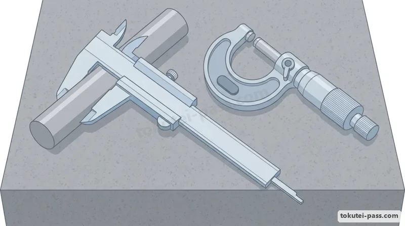
「ノギス(最小読取値 0.05mm等)」は1本で4種類の測定ができる測定器です。外径(外側寸法)は「外側用ジョウ」、穴の内径(内側寸法)は上側の「内側用ジョウ(クチバシ)」、溝や穴の深さは本尺端から出る「デプスバー(深さ測定子)」で測ります(「デプスバーで穴の内径を測る」は誤りです)。
A "vernier caliper (minimum reading 0.05mm, etc.)" can perform four types of measurements with a single tool: outside diameter is measured with the "outer jaws", hole inside diameter with the upper "inner jaws (beaks)", and groove or hole depth with the "depth bar" extending from the end of the main beam (stating that "the depth bar measures hole inside diameter" is incorrect).
板厚や丸棒の外径を「0.01 mm」単位で精密測定する「外側マイクロメータ」は、内部のねじのピッチが「0.5 mm」になっており、回転筒(シンブル)を1回転させると測定面(スピンドル)が「0.5 mm」進みます。
An "outside micrometer", which precisely measures plate thickness or round bar outer diameter in "0.01 mm" increments, has an internal screw pitch of "0.5 mm", so turning the rotating barrel (thimble) 1 full revolution advances the measuring spindle by "0.5 mm".
シンブルの円周上には50等分の目盛りが刻まれており、1目盛りが「0.5 ÷ 50 = 0.01 mm」を表します。読み取るときは、固定筒(スリーブ)の基準線の上側で「1 mm単位」、下側の補助目盛りで「0.5 mm単位」を読み、それにシンブルの「0.01 mm単位」を足し合わせます。
The circumference of the thimble is divided into 50 equal graduations, each representing "0.5 ÷ 50 = 0.01 mm". To read the measurement, read "1 mm increments" above the datum line on the fixed barrel (sleeve) and "0.5 mm increments" on the lower sub-scale, then add the "0.01 mm increments" on the thimble.
例えば、スリーブの上目盛りが7 mmを超え、下目盛りの0.5 mm線が見えており(7.5 mm)、シンブルの目盛り「15(=0.15 mm)」が基準線と一致しているとき、測定値は「7.5 + 0.15 = 7.65 mm」です(0.5 mm目盛りを見落とさないよう注意します)。
For example, when the upper sleeve scale passes 7 mm, the lower 0.5 mm line is visible (7.5 mm), and graduation "15 (= 0.15 mm)" on the thimble aligns with the datum line, the measured value is "7.5 + 0.15 = 7.65 mm" (take care not to overlook the 0.5 mm graduation).
マイクロメータで測定する際は、測定力を一定にするため端の「ラチェットストップ」を空転させて測ります。その他、平面の凹凸や軸の振れを測る「ダイヤルゲージ」、定盤上で高さ測定やけがきを行う「ハイトゲージ」、接合面のすきまを測る「すきまゲージ(シックネスゲージ)」があります。
When measuring with a micrometer, turn the "ratchet stop" at the end until it clicks freely to maintain constant measuring force. Other instruments include "dial gauges" for surface unevenness or shaft runout, "height gauges" for measuring height and scribing on a surface plate, and "feeler (thickness) gauges" for measuring joint clearances.
Key points
- ノギスの「デプスバー」は深さ測定用であり、穴の内径測定には「内側用ジョウ(クチバシ)」を用いる
The "depth bar" of a vernier caliper is for measuring depth, whereas the "inner jaws" are used to measure the inside diameter of a hole - 外側マイクロメータ(最小読取値 0.01mm)は、スリーブの「1mm目盛り+0.5mm目盛り」とシンブルの「0.01mm目盛り」を合計して読む
An outside micrometer (minimum reading 0.01mm) is read by summing the "1mm + 0.5mm graduations" on the sleeve and the "0.01mm graduations" on the thimble - マイクロメータ測定時は、一定の測定力にするため「ラチェットストップ」を使ってスピンドルを当てる
When measuring with a micrometer, use the "ratchet stop" to bring the spindle into contact under constant measuring force
| Word | Meaning |
|---|---|
| ノギス(外側用ジョウ・内側用ジョウ・デプスバー) | Vernier caliper (outer jaws, inner jaws, depth bar) |
| 外側マイクロメータ(最小読取値 0.01mm・ラチェットストップ) | Outside micrometer (0.01mm minimum reading, ratchet stop) |
| スリーブ(0.5mm目盛り)とシンブル(0.01mm目盛り)の読み方 | Reading the sleeve (0.5mm scale) and thimble (0.01mm scale) |
| ダイヤルゲージ・ハイトゲージ・すきまゲージ | Dial gauge, height gauge, and feeler (thickness) gauge |
けがき・手仕上げ・工作機械(旋盤・ボール盤)と応力計算・切り欠き効果
Layout, Hand Finishing, Machine Tools (Lathe, Drilling Machine), Stress Calculation, and Notch Effect
加工前の「けがき作業」において、けがき針で引いたけがき線が消えても分かるように線に沿って小さな点を打つには先端角30°〜60°の「目打ちポンチ」を用い、ドリルで穴をあける中心にドリル先端の逃げ防止用くぼみを打つには先端角90°の「センタポンチ」を用います。
In pre-machining "layout (scribing) work", a "prick punch" with a 30°–60° tip angle is used to punch small witness dots along a scribed line so it remains visible, whereas a "center punch" with a 90° tip angle is used to punch a dimple at the center of a hole to prevent the drill tip from wandering.
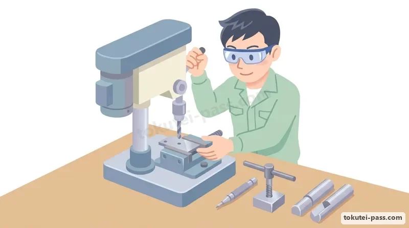
めねじを切る「タップ作業」では、ねじ外径よりピッチ分だけ小さい「タップ下穴(例:M6×1.0ならφ5.0mm)」をドリルであけ、タップハンドルを直角に保って回します。また工作機械のうち、工作物を回転させバイト(刃物)を送って円筒形状に削る機械を「旋盤」といいます。
In "tapping work" to cut internal threads, drill a "tap drill hole" smaller than the thread outer diameter by the pitch (e.g., φ5.0mm for M6×1.0) and turn the tap wrench while keeping it perpendicular. Among machine tools, a machine that rotates the workpiece and feeds a single-point cutting tool (bite) to turn cylindrical shapes is called a "lathe".
これに対し、ドリルやリーマを回転させて穴あけや仕上げを行う機械が「ボール盤」、多刃工具(フライス)を回転させて平面や溝を削る機械が「フライス盤」です。切削加工において、切込み深さや送りを大きくして「切削断面積が大きくなるほど、切削抵抗(削る力)は大きく」なります。
In contrast, a machine that rotates a drill or reamer to drill or finish holes is a "drilling machine (drill press)", and one that rotates a multi-tooth cutter (milling cutter) to machine flat surfaces or slots is a "milling machine". In cutting, increasing depth of cut or feed so that "cutting cross-sectional area increases causes cutting resistance (cutting force) to increase".
単位断面積あたりの内力を「応力 = 荷重 W ÷ 断面積 A」といい、弾性限度内で応力とひずみは比例します。引張荷重 1000N を許容応力 20N/mm² の丸棒で支えるとき、断面積は「1000 ÷ 20 = 50mm²」となり、「0.785 × d² ≥ 50」より直径 d は「約8mm」となります。
Internal force per unit cross-sectional area is "stress = load W ÷ area A", and stress is proportional to strain within the elastic limit. When supporting a tensile load of 1000N with a round bar of allowable stress 20N/mm², the required area is "1000 ÷ 20 = 50mm²", and from circle area "0.785 × d² ≥ 50", the diameter d is "approx. 8mm".
また丸棒や板材に「切り欠き(溝や段差)」があると、その底に応力が集中して破損しやすくなります(切り欠き効果)。同じ深さの切り欠きであれば、鋭いV字形や角形よりも「底の丸み(半径R)が大きい滑らかな円弧形の切り欠き」の方が応力集中が最も少なく強くなります。
Furthermore, if a round bar or plate has a "notch (groove or step)", stress concentrates at its bottom, making it prone to fracture (notch effect). For notches of equal depth, a "smooth circular-arc notch with a large bottom radius (R)" produces the least stress concentration and is strongest compared to sharp V-shaped or square notches.
Key points
- けがき線の確認点には「目打ちポンチ」、穴あけ中心には「センタポンチ」を使い、工作物を回転させバイトで削る工作機械を「旋盤」という
Use a "prick punch" for witness marks along scribed lines and a "center punch" for drill hole centers; a machine tool that rotates the workpiece and cuts with a turning tool is a "lathe" - 引張荷重 1000N・許容応力 20N/mm²のとき、必要断面積は「1000 ÷ 20 = 50mm²」となり、丸棒の直径は「約8mm」となる
For a 1000N tensile load and 20N/mm² allowable stress, the required cross-sectional area is "1000 ÷ 20 = 50mm²", giving a round bar diameter of "approx. 8mm" - 切り欠きのある部材では、角が鋭いものより「底の丸み(R)が大きい円弧状の切り欠き」の方が応力集中が小さく破損しにくい
In notched members, a "circular-arc notch with a large bottom radius (R)" has less stress concentration and resists fracture better than sharp-cornered notches
| Word | Meaning |
|---|---|
| 目打ちポンチとセンタポンチ・ハンドタップ | Prick punch, center punch, and hand tap |
| 旋盤(工作物回転)・ボール盤・フライス盤 | Lathe (rotating workpiece), drilling machine, and milling machine |
| 引張応力計算(応力 = 荷重 ÷ 断面積)とフックの法則 | Tensile stress calculation (stress = load ÷ area) and Hooke's law |
| 切り欠きによる応力集中と丸み(R)の効果 | Stress concentration at notches and the effect of corner radius (R) |
はんだ付け(フラックスの役割と鉛フリーはんだの特徴)と板金・溶接加工
Soldering (Role of Flux and Characteristics of Lead-Free Solder), Sheet Metal Work, and Welding
電気配線や電子基板の「はんだ付け」で使う「フラックス(松脂=ロジン系)」の主な役割は、加熱時に「金属表面の酸化膜(さびや汚れ)を化学的に除去して再酸化を防ぎ、溶けたはんだの表面張力を下げてぬれ性(なじみ)を良くすること」です。
The primary role of "flux (rosin-based)" used in "soldering" electrical wiring and electronic boards is to "chemically remove oxide films (rust or tarnish) from the metal surface during heating, prevent re-oxidation, and lower the surface tension of molten solder to improve wettability (spreading)".
電気機器の配線には腐食性のない「ロジン系フラックス(ヤニ入りはんだ)」を使用し、塩化亜鉛や塩酸などの腐食性フラックス(板金用)は、後日導体を腐食断線させたり絶縁低下を起こすため絶対に使用してはいけません。
Non-corrosive "rosin-based flux (rosin-core solder)" must be used for electrical equipment wiring; corrosive fluxes such as zinc chloride or hydrochloric acid (for sheet metal) must never be used because they later corrode and break conductors or degrade insulation.
近年、環境保全(RoHS指令等による鉛使用規制)のため、すず・銀・銅(Sn-Ag-Cu)などからなる「鉛フリーはんだ(無鉛はんだ)」が標準となっています。
In recent years, for environmental protection (restrictions on lead use under the RoHS Directive, etc.), "lead-free solder" composed of tin, silver, and copper (Sn-Ag-Cu) has become the standard.
鉛フリーはんだは、従来のすず・鉛共晶はんだ(融点 約183℃)に比べて、「融点(溶ける温度)が約217〜220℃と高い」「はんだのぬれ性(広がりやすさ)がやや劣る」「冷却後の表面に光沢が少なく(ざらつきや引け巣が出やすい)」という特徴があります。
Compared to conventional tin-lead eutectic solder (melting point approx. 183℃), lead-free solder is characterized by a "higher melting point of approx. 217–220℃", "slightly poorer solder wettability (spreadability)", and "less surface gloss after cooling (prone to a matte finish or shrinkage cavities)".
また制御盤外箱などの薄鋼板加工では、シャー(せん断機)による切断、プレスブレーキによる曲げ加工(板が元に戻ろうとする「スプリングバック」を見込んで曲げる)、およびスポット溶接(抵抗溶接)やTIG溶接・アーク溶接が用いられます。
Furthermore, in thin steel sheet fabrication for control panel enclosures, shearing machines are used for cutting, press brakes for bending (bending slightly extra to allow for elastic "springback"), along with spot welding (resistance welding), TIG welding, and arc welding.
Key points
- はんだ付け用「フラックス」の主な役割は、金属表面の酸化膜を除き、溶けたはんだの「ぬれ性」を良くすることである
The main role of soldering "flux" is to remove oxide films from metal surfaces and improve the "wettability" of molten solder - 「鉛フリーはんだ」は、従来のすず・鉛はんだに比べて「融点が高く、ぬれ性がやや劣り、表面光沢が少ない」特徴がある
Compared to conventional tin-lead solder, "lead-free solder" features a "higher melting point, slightly poorer wettability, and less surface gloss" - 板金の曲げ加工では、荷重を除いたときに角度がわずかに戻る「スプリングバック」を考慮する
In sheet metal bending, account for "springback", where the bend angle springs back slightly when the load is removed
| Word | Meaning |
|---|---|
| フラックスの役割(酸化膜除去・ぬれ性向上) | Role of flux (oxide film removal and wettability improvement) |
| 鉛フリーはんだ(高融点・ぬれ性・環境対応) | Lead-free solder (high melting point, wettability, RoHS compliance) |
| 板金曲げ加工とスプリングバック | Sheet metal bending and springback |
| スポット溶接(抵抗溶接)とアーク溶接 | Spot welding (resistance welding) and arc welding |
品質管理(QC七つ道具:特性要因図・パレート図・管理図・散布図)と検査
Quality Control (7 QC Tools: Cause-and-Effect, Pareto, Control Chart, Scatter Diagram) and Inspection
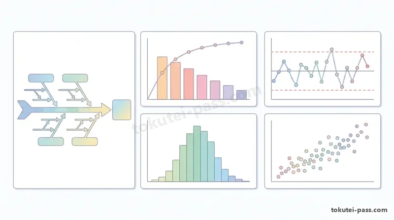
工場の品質管理(QC)で使われる「QC七つ道具」のうち、「特性要因図(魚の骨図)」は、製品の品質特性(結果)とそれに影響を与える要因(材料・機械・作業方法などの原因)との関係を、矢印を使って体系的に整理した図です。
Among the "7 QC Tools" used in factory quality control (QC), a "cause-and-effect diagram (fishbone diagram)" systematically organizes the relationship between a product quality characteristic (effect/result) and the factors affecting it (causes such as materials, machines, and work methods) using arrows.
「パレート図」は、不良やクレームの項目別件数を大きい順に並べた棒グラフと、その累積比率(%)を示す折れ線(累積曲線)を組み合わせた図であり、どの不良項目を優先的に改善すべきか(重点指向)を一目で把握できます。
A "Pareto chart" combines a bar graph arranging defect or complaint counts by category in descending order with a line graph showing cumulative percentage (cumulative curve), making it immediately clear which defect item should be prioritized for improvement.
「管理図(Xバー・R管理図等)」は、製造工程が安定した状態にあるかどうかを判定するため、中心線(CL)の上下に上方管理限界線(UCL)と下方管理限界線(LCL)を引き、時系列の測定値を打点して異常原因の有無を監視する図です。
A "control chart (such as an X-bar-R control chart)" determines whether a manufacturing process is in a stable state by drawing an upper control limit (UCL) and lower control limit (LCL) above and below a center line (CL) and plotting time-series measurements to monitor for abnormal causes.
「ヒストグラム(柱状図)」は測定値の存在する範囲をいくつかの区間に分けて度数を棒の高さで表し、データのばらつきや平均値の分布状態を見る図です。また「散布図」は、対になった2つの変数(xとy)を縦軸と横軸にとって打点し、2つのデータ間の「相関関係」を調べる図です。
A "histogram" divides the range of measured values into intervals and represents frequency by bar height to observe data dispersion and mean distribution. A "scatter diagram" plots paired variables (x and y) on vertical and horizontal axes to examine the "correlation" between two datasets.
学科試験では「特性要因図の説明と管理図の説明を入れ替える」や「散布図の説明としてパレート図の定義を書く」ひっかけが毎年出題されます。また検査には全品を調べる「全数検査」と、ロットから試料を抜き取る「抜取り検査(破壊試験等に不可欠)」があります。
Written exams every year feature trick questions that "swap the explanations of cause-and-effect diagrams and control charts" or "give the definition of a Pareto chart as the explanation for a scatter diagram". Inspections include "100% (full) inspection" and "sampling inspection (essential for destructive testing)".
Key points
- 品質の「結果(特性)」と「原因(要因)」の関係を魚の骨状に整理した図を「特性要因図」という
A diagram organizing the relationship between quality "effects (characteristics)" and "causes (factors)" in a fishbone shape is called a "cause-and-effect diagram" - 不良項目を件数順の棒グラフと累積曲線で表す図を「パレート図」、2変数間の相関を見る図を「散布図」という
A chart showing defect items as a descending bar graph with a cumulative curve is a "Pareto chart", and a diagram examining correlation between 2 variables is a "scatter diagram" - 上下の「管理限界線(UCL・LCL)」を引き、工程が安定状態にあるかを監視する図を「管理図」という
A chart with upper and lower "control limit lines (UCL, LCL)" used to monitor whether a process is in a stable state is called a "control chart"
| Word | Meaning |
|---|---|
| 特性要因図(結果と原因の体系的整理) | Cause-and-effect diagram (systematic organization of effects and causes) |
| パレート図(棒グラフ+累積曲線)とヒストグラム | Pareto chart (bar graph + cumulative curve) and histogram |
| 管理図(上方・下方管理限界線と工程安定監視) | Control chart (upper/lower control limits and process stability monitoring) |
| 散布図(相関関係)と全数検査・抜取り検査 | Scatter diagram (correlation), 100% inspection, and sampling inspection |
Materials, Machining & Quality Control
Practice this chapter in the appOfficial references
- 中央職業能力開発協会(JAVADA)「技能検定 電気機器組立て 2級 学科試験基準(電気材料・機械要素・機械工作法・品質管理)」 — https://www.javada.or.jp/jigyou/gino/giken.html
- 日本産業規格「JIS C 4003 電気絶縁の耐熱クラス及び耐熱性評価」「JIS Z 8101 品質管理用語」 — https://www.jisc.go.jp/