
Electrical Construction Methods, Inspection & Measurement, and the First-Class Practical Exam
電気工事の施工方法・検査測定と第一種技能試験
Class 1 Electrician 第一種電気工事士 (written exam) · 第一種電気工事士(学科試験) · Written by Tokutei Pass based on the official study texts; not copied verbatim.
低圧屋内配線工事の支持点間距離と接地省略基準
Support Intervals and Grounding Exemption Rules in Low-Voltage Indoor Wiring
工場等の低圧屋内配線では、最大支持点間距離が頻出です。造営材に沿わせる場合、ケーブル工事は「2m 以下(垂直 6m 以下)」、合成樹脂管は「1.5m 以下」、金属管は「2m 以下」、バスダクトは「3m 以下」、ライティングダクトは「2m 以下」で支持します。
In low-voltage indoor wiring for factories and buildings, the maximum distance between support points (最大支持点間距離) is a frequent exam topic. When installed along building surfaces, cable work must be supported at intervals of 2m or less (6m or less vertically), synthetic resin conduits (合成樹脂管) at 1.5m or less, metal conduits (金属管) at 2m or less, bus ducts at 3m or less, and lighting ducts at 2m or less.
店舗照明等に使うライティングダクト工事では、ほこりの侵入や感電を防ぐため、ダクトの開口部を「下向き(または横向き)」に施設し、「上向き」に施設することは禁止されています。また終端はエンドキャップで塞ぎ、D種接地工事を施します。
In lighting duct work (ライティングダクト工事) used for store lighting, to prevent dust entry and electric shock, the duct opening must be installed facing downward (or sideways); installing the opening facing upward (上向き) is prohibited. Also, the end of the duct must be closed with an end cap and given Class D grounding.
金属線ぴ(メタルモール)工事は「乾燥した点検できる展開した場所」に限り施設でき、内部には IV 線等の絶縁電線を収めますが、絶縁性能の低い「屋外用ビニル絶縁電線(OW)」は使用できません。また線ぴの長さが「4m 以下」であれば D種接地工事を省略できます。
Metal raceway / molding work (金属線ぴ / メタルモール工事) may only be installed in dry, accessible, exposed locations; insulated wires such as IV wire are placed inside, but outdoor vinyl-insulated wire (OW), which has lower insulation performance, cannot be used. Also, if the raceway length is 4m or less, Class D grounding may be omitted.
金属管工事では「乾燥場所で管長 4m 以下」または「対地電圧 150V 以下で管長 8m 以下(簡易接触防護措置または乾燥場所)」なら D種接地を省略できます。一方、「ケーブルラック」や「2種金属可とう電線管」は乾燥場所 4m 以下でも接地を省略できません。
In metal conduit work (金属管工事), Class D grounding may be omitted if the conduit length is 4m or less in a dry location, or if the voltage to ground is 150V or less and the conduit length is 8m or less (with simple contact protection or in a dry location). Conversely, for cable racks (ケーブルラック) and Type 2 flexible metal conduits (2種金属可とう電線管), grounding cannot be omitted even if they are 4m or less in a dry location.
使用電圧 300V 超(400V 級)の金属管や金属ダクトには原則 C種接地工事(10Ω 以下)が必要ですが、人が触れるおそれがないよう「接触防護措置」を施した場合に限り、D種接地工事(100Ω 以下)に緩和することができます。
Metal conduits and metal ducts operating at over 300V (400V class) require Class C grounding (10Ω or less) in principle, but if contact protection measures (接触防護措置) are applied so that people cannot touch them, this can be relaxed to Class D grounding (100Ω or less).
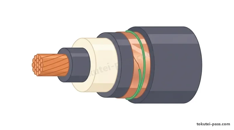
Key points
- 最大支持点間距離:合成樹脂管=1.5m、ケーブル・金属管・ライティングダクト=2m、バスダクト=3m
Maximum support intervals: Synthetic resin conduit = 1.5m; Cable, Metal conduit, Lighting duct = 2m; Bus duct = 3m - ライティングダクトの開口部は「上向き禁止(下向き・横向きは可)」。金属線ぴに「OW 線」は使用不可
Lighting duct openings must never face upward (downward or sideways is allowed). OW wire cannot be used inside metal raceways (金属線ぴ) - D種接地省略:金属線ぴ(4m以下)と金属管(乾燥 4m以下)は省略可だが、「ケーブルラック」は長さに関わらず省略不可
Class D grounding exemption: Metal raceways (≤ 4m) and metal conduits (≤ 4m in dry locations) can omit grounding, but cable racks (ケーブルラック) can never omit grounding regardless of length - 300V 超(400V 級)の金属管・金属ダクトは原則 C種接地だが、「接触防護措置」を施せば D種接地でよい
Metal conduits and metal ducts over 300V (400V class) require Class C grounding in principle, but Class D grounding is permitted if contact protection measures are applied
| Word | Meaning |
|---|---|
| 支持点間距離 | 支持点間距離 (しじてんかんきょり): Distance between support points |
| ライティングダクト・バスダクト | ライティングダクト・バスダクト: Lighting duct and Bus duct |
| 金属線ぴ(メタルモール) | 金属線ぴ (メタルモール): Metal raceway / Metal molding |
| ケーブルラック | ケーブルラック: Cable rack |
| 接触防護措置 | 接触防護措置 (せっしょくぼうごそち): Contact protection measures |
特殊場所・太陽電池・高圧架空および地中電線路の施工
Construction in Hazardous Locations, Solar PV, and High-Voltage Overhead / Underground Lines
可燃性ガスや引火性蒸気が存在する危険場所や、小麦粉・でんぷん等の可燃性粉じん場所では、「厚鋼電線管」または「ケーブル(MI ケーブルや鎧装ケーブル、金属管保護)」で施工し、合成樹脂管は使用できません。電動機端子部には「防爆形可とう電線管(フレキシブルフィッチング)」を用います。
In hazardous locations containing flammable gases or vapors, or combustible dust locations (such as flour or starch), wiring must use thick steel conduits (厚鋼電線管) or cables (MI cables, armored cables, or cables protected in metal pipes); synthetic resin conduits cannot be used. Explosion-proof flexible fittings (防爆形可とう電線管) are used at motor terminal connections.
太陽電池発電設備で直流電圧が 450V の場合、直流 750V 以下は低圧ですが 300V 超のため、外箱や架台には「C種接地工事(10Ω 以下)」を施します。また三相3線式 210V 動力回路には「3極3素子(3P3E)」の遮断器を設置します(3極2素子は不可)。
In a solar photovoltaic system with a DC working voltage of 450V, although DC 750V or less is classified as low voltage, because it exceeds 300V, metal enclosures and frames must receive Class C grounding (10Ω or less). Also, a 3-phase 3-wire 210V motor circuit must use a 3-pole 3-element (3極3素子 / 3P3E) molded-case circuit breaker (a 3-pole 2-element breaker is not permitted).
高圧屋側・架空電線路をケーブルで施設する場合、ケーブルを吊る「ちょう架用線」には引張強さ 5.93kN 以上かつ断面 22mm² 以上の亜鉛めっき鋼より線を用い、安全率「2.5 以上」、ハンガ間隔「0.5m 以下」で支持し、A種接地工事を施します。
When installing high-voltage building-side or overhead lines using cables, the messenger wire (ちょう架用線) supporting the cable must be a galvanized steel strand with a tensile strength of at least 5.93kN and cross-section of at least 22mm², strung with a safety factor of at least 2.5, supported by hangers at intervals of 0.5m or less, and given Class A grounding.
高圧架空引込線の地表上高さは原則「5m 以上(危険のおそれがない場合は 4m 以上、道路横断 6m 以上)」です。また高圧地中電線路の直接埋設深さは「車両等の重量物圧力を受ける場所は 1.2m 以上、その他の場所は 0.6m 以上」とします。
The height above ground of high-voltage overhead service drops (高圧架空引込線) must in principle be at least 5m (at least 4m where there is no traffic obstruction and no danger; at least 6m across roads). For direct burial of high-voltage underground cables on premises, burial depth must be at least 1.2m in places subject to heavy vehicle pressure, and at least 0.6m in other places.
地中電線路には必ず「ケーブル」を使用し、「絶縁電線(IV・KIP 等)」は使用できません。防護管にはトラフや防水鋳鉄管等を使えますが「白ガス管」は不適切です。また地中高圧線路の長さが「15m を超える」場合は埋設表示シート等を設けます。
Underground power lines must always use cables (ケーブル); insulated wires (絶縁電線 such as IV or KIP) can never be used. Protective troughs or waterproof cast-iron pipes may be used, but galvanized gas pipes (白ガス管) are improper. Also, if a high-voltage underground line exceeds 15m in length, an underground warning sheet indicating the facility name and manager must be installed.
Key points
- 危険場所・粉じん場所は「厚鋼電線管」または「ケーブル工事」とし、電動機接続部には「防爆形可とう電線管」を使用
Hazardous gas and combustible dust locations require thick steel conduit or cable work, with explosion-proof flexible conduits at motor connections - 高圧ケーブルのちょう架用線:安全率 2.5以上、ハンガ間隔 0.5m以下、A種接地工事。高圧引込線の高さ:原則 5m以上(支障なし 4m以上)
High-voltage cable messenger wire: safety factor ≥ 2.5, hanger interval ≤ 0.5m, Class A grounding. High-voltage service drop height: ≥ 5m in principle (≥ 4m if no hazard) - 高圧地中電線路の直接埋設深さ:重量物圧力あり「1.2m以上」、なし「0.6m以上」。長さ 15m超で埋設表示が必要
High-voltage underground direct burial depth: ≥ 1.2m under vehicle pressure, ≥ 0.6m elsewhere. Warning sheet required if length exceeds 15m - 地中電線路に「絶縁電線」は使用禁止(必ずケーブル)。三相3線式 210V 回路の遮断器は「3極3素子」が必要
Insulated wires (絶縁電線) are prohibited underground (must use cables). A 3-phase 3-wire 210V circuit breaker must be 3-pole 3-element (3P3E)
| Word | Meaning |
|---|---|
| 防爆形可とう電線管 | 防爆形可とう電線管: Explosion-proof flexible conduit |
| ちょう架用線(メッセンジャーワイヤ) | ちょう架用線 (メッセンジャーワイヤ): Messenger wire |
| 直接埋設式(1.2m・0.6m) | 直接埋設式 (1.2m・0.6m): Direct burial method (1.2m / 0.6m depth) |
| 埋設表示シート(15m超) | 埋設表示シート (15m超): Underground burial warning sheet (over 15m) |
| 3極3素子(3P3E) | 3極3素子 (3P3E): 3-pole 3-element circuit breaker |
A種・B種・C種・D種接地工事の総整理
Complete Summary of Class A, Class B, Class C, and Class D Grounding
A種接地工事は「高圧・特別高圧機器の金属製外箱・鉄台、キュービクル外箱、避雷器(LA)、高圧ケーブルの金属シース(遮蔽層)・ちょう架用線」に施します。接地抵抗値は「10Ω 以下」、接地線(軟銅線)の太さは「断面積 5.5mm² 以上(避雷器 LA は 14mm² 以上)」です。
Class A grounding (A種接地工事) is applied to metal enclosures and frames of high-voltage and extra-high-voltage equipment, cubicle enclosures, lightning arresters (LA), and metallic sheaths/messenger wires of high-voltage cables. Grounding resistance must be 10Ω or less, and the soft copper grounding wire cross-section must be at least 5.5mm² (at least 14mm² for lightning arresters LA).
B種接地工事は高低圧混触防止のため「変圧器の低圧側中性点または 1端子」に施します。抵抗値は 1線地絡電流 I1(A)から原則「150 ÷ I1(Ω)以下」ですが、高圧側が 1秒超〜2秒以内に遮断されるなら「300 ÷ I1」、1秒以内なら「600 ÷ I1」以下となります。
Class B grounding (B種接地工事) is applied to the low-voltage neutral point or one terminal of a transformer to prevent high-to-low-voltage contact (高低圧混触防止). Grounding resistance using the 1-line ground fault current I1 (A) is in principle 150 ÷ I1 (Ω) or less; if the high-voltage side automatically trips within 1 to 2 seconds, it is 300 ÷ I1, and if within 1 second, 600 ÷ I1 or less.
B種接地線の太さは、高圧側の遮断方式により決まります。原則(LBS+PF など)は「断面積 8mm² 以上(または直径 4.0mm 以上)」であり、高圧側が 1秒以内に自動遮断される場合や別規定で「14mm² 以上」が求められるケースと合わせて、最低でも 8mm² 以上が必要です。
The size of a Class B grounding wire depends on the high-voltage interruption method. In principle (such as with LBS + PF), the cross-section must be at least 8mm² (or diameter at least 4.0mm); combined with cases requiring at least 14mm² when interrupted within 1 second, a minimum of at least 8mm² is required.
C種接地工事は「300V を超える低圧機器(400V 級電動機・太陽電池 450V 等)の鉄台・金属外箱」に施し、抵抗値は「10Ω 以下(地絡遮断装置が 0.5秒以内に動作するときは 500Ω 以下)」、接地線は「直径 1.6mm 以上」です。
Class C grounding (C種接地工事) is applied to frames and metal enclosures of low-voltage equipment operating at over 300V (400V-class motors, 450V solar PV, etc.); grounding resistance must be 10Ω or less (500Ω or less if a ground-fault interrupter trips within 0.5 seconds), and the grounding wire diameter must be at least 1.6mm.
D種接地工事は「300V 以下の低圧機器」に加えて、「高圧計器用変成器(CT・VT・VCT)の二次側回路」に施すのが最頻出です(特別高圧の二次側は A種)。抵抗値は「100Ω 以下(0.5秒以内遮断で 500Ω 以下)」、接地線は「φ1.6mm 以上(VCT 二次側 3.5mm² 以上)」です。
Class D grounding (D種接地工事), in addition to low-voltage equipment of 300V or less, is applied to the secondary circuits of high-voltage instrument transformers (CT, VT, VCT) — this is the most frequently tested point (extra-high-voltage CT/VT secondaries require Class A). Resistance is 100Ω or less (500Ω or less with 0.5-second interruption), and wire diameter is at least φ1.6mm (at least 3.5mm² for VCT secondary).
Key points
- A種接地(高圧機器外箱・シース):10Ω以下、太さ 5.5mm²以上(避雷器 LA の接地線は 14mm²以上)
Class A grounding (HV equipment enclosures, cable sheaths): ≤ 10Ω, wire ≥ 5.5mm² (lightning arrester LA grounding wire must be ≥ 14mm²) - B種接地(変圧器低圧側):150÷I1 Ω以下(2秒以内遮断は 300÷I1、1秒以内は 600÷I1)、太さ 8mm²以上(または 14mm²以上)
Class B grounding (transformer LV side): ≤ 150÷I1 Ω (300÷I1 for ≤ 2s trip, 600÷I1 for ≤ 1s trip), wire ≥ 8mm² (or ≥ 14mm²) - C種接地(300V超低圧):10Ω以下、D種接地(300V以下低圧):100Ω以下(ともに 0.5秒以内遮断で 500Ω以下、太さ φ1.6mm以上)
Class C grounding (LV > 300V): ≤ 10Ω; Class D grounding (LV ≤ 300V): ≤ 100Ω (both relaxed to ≤ 500Ω if interrupted within 0.5s; wire ≥ φ1.6mm) - 高圧用の変流器(CT)・計器用変圧器(VT)・VCT の「二次側回路」は D種接地工事(A種ではない点に注意!)
The secondary circuits of high-voltage CTs, VTs, and VCTs require Class D grounding (be careful: not Class A!)
| Word | Meaning |
|---|---|
| A種接地工事(10Ω・5.5mm²) | A種接地工事 (10Ω・5.5mm²): Class A grounding (LA requires ≥ 14mm²) |
| B種接地工事(150÷I1・8mm²) | B種接地工事 (150÷I1・8mm²): Class B grounding (HV/LV contact protection) |
| C種接地工事(10Ω・φ1.6mm) | C種接地工事 (10Ω・φ1.6mm): Class C grounding (LV over 300V) |
| D種接地工事(100Ω・φ1.6mm) | D種接地工事 (100Ω・φ1.6mm): Class D grounding (LV ≤ 300V and HV CT/VT secondary) |
| 1線地絡電流(I1) | 1線地絡電流 (I1): Single-line-to-ground fault current (I1) |
高圧絶縁耐力試験と接地抵抗・絶縁抵抗測定
High-Voltage Dielectric Strength Test and Earth / Insulation Resistance Measurement
高圧受電設備の竣工時に行う「絶縁耐力試験」では、公称電圧 6,600V 回路の最大使用電圧 E を「6,600 × (1.15 ÷ 1.1) = 6,900V」として計算します。最大使用電圧 7,000V 以下の高圧電路では、最大使用電圧の「1.5倍」の交流試験電圧を「連続して 10分間」加えます。
In the dielectric strength test (絶縁耐力試験) performed upon completion of a high-voltage receiving substation, the maximum working voltage E of a nominal 6,600V circuit is calculated as 6,600 × (1.15 ÷ 1.1) = 6,900V. For high-voltage circuits with a maximum working voltage of 7,000V or less, an AC test voltage of 1.5 times the maximum working voltage is applied continuously for 10 minutes.
したがって 6,600V 高圧電路の交流試験電圧は「6,900V × 1.5 = 10,350V(連続 10分間)」となります。また高圧ケーブルを直流電圧で試験する場合は、交流試験電圧の 2倍である「10,350V × 2 = 20,700V(連続 10分間)」を加えます。
Therefore, the AC test voltage for a 6,600V high-voltage circuit is 6,900V × 1.5 = 10,350V (continuously for 10 minutes). Furthermore, when testing high-voltage cables with DC voltage, a DC voltage of twice the AC test voltage, namely 10,350V × 2 = 20,700V (continuously for 10 minutes), is applied.
絶縁耐力試験では、高電圧で破損する「避雷器(LA)、計器用変圧器(VT)一次側、進相コンデンサの放電コイル、零相電圧検出装置(ZPD)」などをあらかじめ切り離し、三相一括と大地(接地)の間に試験電圧を印加します。
During a dielectric strength test, devices that would be damaged by high voltage to ground — such as lightning arresters (LA), primary windings of voltage transformers (VT), discharge coils of power capacitors, and zero-phase voltage detectors (ZPD) — are disconnected beforehand, and the test voltage is applied between all three phases connected together and earth.
高圧ケーブルの絶縁抵抗を高圧メガで測定する際は、心線に「L端子」、金属シースに「E端子」を接続し、端末表面の漏れ電流による誤差を除くため、絶縁体表面に巻いた裸銅線に「ガード端子(G)」を接続します。
When measuring the insulation resistance of a high-voltage cable with a high-voltage Megger, connect the L terminal to the core conductor and the E terminal to the metallic sheath; to eliminate measurement error caused by surface leakage current along the termination insulation surface, connect the Guard terminal (G — ガード端子) to a bare copper wire wrapped around the insulation surface.
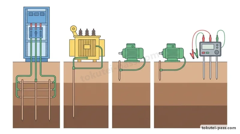
接地抵抗計(アーステスタ)による測定では、被測定接地極「E」から一直線上に約 10m ずつ離して補助極の「P(S:電位極)」、さらに外側に「C(H:電流極)」の順(E − P − C の順)で地面に打ち込みます。測定前にはまず地電圧が規定値以下であることを確認します。
When measuring with an earth resistance tester (接地抵抗計), drive the auxiliary electrodes into the ground in a straight line from the grounding electrode under test E at intervals of about 10m in the order: potential electrode P (S) in the middle, and current electrode C (H) on the outside (order E − P − C). Before measuring, verify that earth voltage is below the specified limit.
Key points
- 6,600V 高圧回路の最大使用電圧は 6,900V。絶縁耐力試験は「交流 10,350V(1.5倍)を連続 10分間」印加する
Maximum working voltage of a 6,600V circuit is 6,900V. The dielectric strength test applies AC 10,350V (1.5×) continuously for 10 minutes - 6,600V 高圧ケーブルを直流で絶縁耐力試験する場合は「直流 20,700V(交流試験電圧の 2倍)を連続 10分間」印加
When testing a 6,600V high-voltage cable with DC, apply DC 20,700V (twice the AC test voltage) continuously for 10 minutes - 高圧ケーブルの絶縁抵抗測定では、端末表面の漏れ電流を除くため絶縁体表面に「ガード端子(G)」を接続する
When measuring insulation resistance of a high-voltage cable, connect the Guard terminal (G) to the insulation surface to eliminate surface leakage current - 接地抵抗測定の補助極配置:一直線上に約 10m 間隔で「E(接地極)→ P(電位極)→ C(電流極)」の順に配置
Auxiliary electrode placement for earth resistance measurement: in a straight line at approx. 10m intervals in the order E (earth) → P (potential) → C (current)
| Word | Meaning |
|---|---|
| 最大使用電圧(6,900V) | 最大使用電圧 (6,900V): Maximum working voltage of a 6.6kV system |
| 絶縁耐力試験(10,350V・10分間) | 絶縁耐力試験 (10,350V・10分間): Dielectric strength test (AC 10,350V for 10 min) |
| ガード端子(G) | ガード端子 (G): Guard terminal (eliminates surface leakage current) |
| 接地抵抗計(E・P・C) | 接地抵抗計 (E・P・C): Earth resistance tester (E - P - C electrode order) |
保護継電器試験・絶縁油診断と定期自主検査
Protective Relay Testing, Insulating Oil Diagnosis, and Periodic Voluntary Inspection
地絡方向継電器(DGR)の試験は「最小動作電流・最小動作電圧・位相特性・動作時間特性試験」であり、「動作周波数試験」は不要です。また過電流継電器(OCR)の試験では CTT 等で「CT 二次側を短絡」し、「最小動作電圧試験」は不要です。
Test items for a directional ground relay (DGR) are minimum operating current, minimum operating voltage, phase characteristic, and operating time characteristic tests; an operating frequency test (動作周波数試験) is unnecessary. For overcurrent relay (OCR) testing, short-circuit the CT secondary at the current test terminal (CTT), and a minimum operating voltage test is unnecessary.
油入変圧器の絶縁油劣化診断では、「絶縁破壊電圧試験(絶縁耐力)」「酸価度測定(酸化劣化判定)」「油中ガス分析(内部過熱・放電診断)」「水分測定」を行います。「真空度測定」は VCB の検査であり、絶縁油試験ではありません。
In deterioration diagnosis of insulating oil in oil-immersed transformers, dielectric breakdown voltage testing, acid value measurement (酸価度測定 — judging oxidation deterioration), dissolved gas analysis (油中ガス分析 — diagnosing internal overheating or discharge), and moisture measurement are performed. Vacuum degree measurement (真空度測定) is an inspection for vacuum circuit breakers (VCB), not insulating oil.
自家用電気工作物の竣工検査項目には「外観検査・接地抵抗測定・絶縁抵抗測定・絶縁耐力試験・保護装置およびインターロックの動作試験」があります。機器製造工場で行う「温度上昇試験」や「短絡強度試験」は現場の竣工検査では行いません。
Completion inspection (竣工検査) items for private electrical installations include visual inspection, earth resistance measurement, insulation resistance measurement, dielectric strength testing, and operational testing of protective devices and interlocks. Temperature rise tests (温度上昇試験) and short-circuit strength tests are factory tests and are not performed during on-site completion inspections.
労働安全衛生規則により、高圧活線作業等で使う絶縁用保護具(ゴム手袋・絶縁長靴・安全帽)および絶縁用防具(絶縁シート等)は、「6か月以内ごとに 1回」絶縁性能の自主検査を行い、記録を「3年間」保存します。
Under the Ordinance on Industrial Safety and Health, insulating protective equipment (rubber gloves, insulating boots, safety helmets) and insulating shields (insulating sheets, etc.) used in high-voltage live-line work must undergo periodic voluntary inspection of their insulating performance at least once every 6 months, and the inspection records must be preserved for 3 years.
また停電できない低圧電路で絶縁抵抗測定が困難な場合は、クランプ形漏れ電流計を用いて使用状態のまま漏れ電流を測定し、「1mA 以下」であれば絶縁性能が適合していると判定できます。
Additionally, in low-voltage circuits that cannot be de-energized where insulation resistance measurement is difficult, measure leakage current during operation using a clamp-type leakage current meter; if the leakage current is 1mA or less, the insulation performance is judged compliant.
Key points
- DGR 試験に「動作周波数試験」は不要。OCR 試験に「最小動作電圧試験」は不要(試験時は CT 二次側を短絡する)
DGR testing does not require an operating frequency test. OCR testing does not require a minimum operating voltage test (short-circuit CT secondary during testing) - 変圧器絶縁油の劣化診断=絶縁耐力・酸価度・油中ガス分析(「真空度測定」は VCB 用であり誤り)
Transformer oil diagnosis = dielectric strength, acid value, dissolved gas analysis (vacuum degree measurement is for VCBs and is wrong) - 現場の竣工検査に「温度上昇試験」は含まれない。低圧電路の漏れ電流は「1mA 以下」で合格
On-site completion inspection does not include a temperature rise test (温度上昇試験). Low-voltage circuit leakage current passes if ≤ 1mA - 絶縁用保護具・防具の定期自主検査:「6か月以内ごとに 1回」実施し、記録を「3年間」保存する
Periodic voluntary inspection of insulating protective gear: perform once every 6 months and keep records for 3 years
| Word | Meaning |
|---|---|
| 地絡方向継電器試験(DGR試験) | 地絡方向継電器試験 (DGR試験): Directional ground relay (DGR) test |
| 酸価度測定・油中ガス分析 | 酸価度測定・油中ガス分析: Acid value measurement and Dissolved gas analysis in oil |
| 竣工検査 | 竣工検査 (しゅんこうけんさ): Completion inspection |
| 定期自主検査(6か月・3年保存) | 定期自主検査 (6か月・3年保存): Periodic voluntary inspection (every 6 months, keep 3 years) |
第一種電気工事士 技能試験の概要と欠陥判断基準
Overview of the First-Class Practical Exam and Defect Judgment Criteria
学科試験合格後(または免除)に受験する第一種電気工事士の「技能試験」は、事前に公表される「候補問題 10問(No.1〜No.10)」の中から 1問が出題され、試験時間「60分間」で単線図から複線図を起こして支給材料で工作物を完成させる実技試験です。
The First-Class Electrician Practical Exam (技能試験), taken after passing (or being exempted from) the written exam, presents 1 problem out of 10 pre-published candidate problems (候補問題 No.1–No.10). Within a 60-minute time limit, candidates must draw a multi-line wiring diagram from a single-line diagram and assemble the installation using supplied materials.
第二種(低圧住宅配線・40分間)と異なり、第一種では高圧受電設備の変圧器・CT・VT・開閉器代用端子台や、低圧動力制御回路(押しボタン・表示灯・電磁接触器・タイマ等)を組み合わせた課題が出題されます。
Unlike the Second-Class practical exam (low-voltage residential wiring, 40 minutes), the First-Class exam combines high-voltage receiving equipment such as transformers (T), current transformers (CT), voltage transformers (VT), and terminal blocks representing switches with low-voltage motor control circuits (pushbuttons, indicator lamps, electromagnetic contactors, timers, etc.).
第一種の支給電線には、高圧側配線として被覆が厚い「高圧絶縁電線 KIP 8mm²(黒)」が使われ、CT・VT 二次側や制御回路には「制御用ケーブル CVV 2.0mm²(2心・3心)」や IV 線、低圧幹線には VVR・VVF が使われます。
Among supplied wires in the First-Class exam, thick-insulated high-voltage ethylene-propylene rubber insulated wire KIP 8mm² (black) is used for high-voltage wiring; control vinyl-insulated vinyl-sheathed cable CVV 2.0mm² (2-core, 3-core) and IV wire are used for CT/VT secondaries and control circuits; and VVR or VVF cables are used for low-voltage feeders.
合否は「欠陥が 1つでもあれば不合格」となります。特に高圧用端子台(変圧器一次側など KIP 線接続部)では、端子から心線(裸線)が「20mm 以上露出」している場合に欠陥となります(低圧用端子台では裸線露出「5mm 以上」で欠陥)。
Pass/fail is determined on a zero-tolerance basis where even a single defect (欠陥) results in failure. In particular, at high-voltage terminal blocks (such as transformer primary KIP wire connections), exposing 20mm or more of bare core wire outside the terminal is judged a defect (whereas at low-voltage terminal blocks, exposing 5mm or more of bare wire is a defect).
またリングスリーブ圧着接続では、1.6mm 2本のみ「〇(極小)」刻印、1.6mm 3〜4本や 2.0mm 1本+1.6mm 1〜2本等は「小」刻印、2.0mm 3〜4本等は「中」刻印とし、刻印誤りや心線先端が 5mm 超突き出る場合も欠陥です。
Furthermore, for ring-sleeve crimp connections, joining two 1.6mm wires requires the '〇' (extra-small) die mark; joining three to four 1.6mm wires or one 2.0mm + one to two 1.6mm wires requires the '小' (small) mark; and joining three to four 2.0mm wires requires the '中' (medium) mark. An incorrect crimp mark or core wire protruding more than 5mm beyond the sleeve is also a defect.
Key points
- 第一種技能試験:試験時間「60分間」、事前公表の候補問題 10問、欠陥が 1つでもあれば不合格
First-Class Practical Exam: 60-minute time limit, 10 pre-published candidate problems, even 1 defect results in failure - 第一種特有の電線:高圧配線には「KIP 8mm²」、制御・計器回路には「CVV 2.0mm²(2心・3心)」を使用
Wires unique to First-Class: KIP 8mm² for high-voltage wiring, and CVV 2.0mm² (2-core, 3-core) for control and instrument circuits - 端子台の心線露出欠陥基準:高圧端子台(KIP)は「20mm 以上露出」で欠陥、低圧端子台は「5mm 以上露出」で欠陥
Terminal block bare wire exposure defect criteria: ≥ 20mm exposed is a defect on high-voltage terminal blocks (KIP); ≥ 5mm exposed is a defect on low-voltage terminal blocks - リングスリーブ圧着刻印:1.6mm×2本=「〇(極小)」、1.6mm×3〜4本または 2.0mm×2本=「小」、2.0mm×3〜4本=「中」
Ring-sleeve crimp marks: 1.6mm × 2 = '〇' (extra-small); 1.6mm × 3–4 or 2.0mm × 2 = '小' (small); 2.0mm × 3–4 = '中' (medium)
| Word | Meaning |
|---|---|
| 技能試験(60分間・候補問題10問) | 技能試験 (60分間・候補問題10問): Practical skill exam (60 min, 10 candidate problems) |
| 高圧絶縁電線(KIP 8mm²) | 高圧絶縁電線 (KIP 8mm²): High-voltage EP-rubber insulated wire (KIP 8mm²) |
| 制御用ケーブル(CVV) | 制御用ケーブル (CVV): Control cable (CVV 2.0mm²) |
| 欠陥の判断基準 | 欠陥の判断基準: Defect judgment criteria (bare wire exposure ≥ 20mm HV / ≥ 5mm LV) |
| リングスリーブ圧着刻印(〇・小・中) | リングスリーブ圧着刻印 (〇・小・中): Ring-sleeve crimp die marks (〇, 小, 中) |
試験によく出るポイントと覚え方
Key Exam Points and Memory Tricks
施工の数字は「バスダクト=3m、ケーブル・金属管・ライティングダクト=2m、合成樹脂管=1.5m、高圧ハンガ=0.5m、高圧地中埋設=重量物 1.2m・その他 0.6m(表示シート 15m 超)」を整理しましょう。ケーブルラックは 4m 以下でも接地省略不可です。
Organize construction numbers together: Bus duct = 3m; Cable, Metal conduit, Lighting duct = 2m; Synthetic resin conduit = 1.5m; High-voltage hanger = 0.5m; High-voltage underground burial = 1.2m under heavy loads / 0.6m elsewhere (warning sheet over 15m). Cable racks can never omit grounding even if 4m or less.
接地工事のひっかけは、①「高圧 CT・VT の二次側は D種接地(A種ではない)」、②「避雷器 LA の A種接地線は 14mm² 以上(通常 A種は 5.5mm² 以上)」、③「B種接地抵抗=150÷I1(2秒 300÷I1、1秒 600÷I1)、太さ 8mm² 以上」です。
The top three grounding traps are: (1) High-voltage CT and VT secondaries require Class D grounding (not Class A); (2) Lightning arrester LA Class A grounding wire must be ≥ 14mm² (normal Class A is ≥ 5.5mm²); (3) Class B grounding resistance = 150÷I1 (300÷I1 for 2s, 600÷I1 for 1s), wire size ≥ 8mm².
6,600V 絶縁耐力試験は「最大使用電圧 6,900V × 1.5 = 交流 10,350V を連続 10分間(直流試験は 2倍の 20,700V を 10分間)」と暗記すれば即答できます。高圧ケーブルの絶縁抵抗測定では表面漏れ電流除去用の「G(ガード)端子」を絶縁体表面につなぎます。
For the 6,600V dielectric strength test, memorize: Maximum working voltage 6,900V × 1.5 = AC 10,350V continuously for 10 minutes (for DC tests, twice that = 20,700V for 10 minutes) for an instant answer without calculation. When measuring high-voltage cable insulation resistance, connect the G (Guard) terminal to the insulation surface to remove surface leakage current.
検査の誤り選択肢は「DGR の動作周波数試験」「OCR の最小動作電圧試験」「絶縁油の真空度測定」「竣工検査の温度上昇試験」です。また絶縁用保護具の定期自主検査は「6か月ごと・記録 3年保存」です。
Classic wrong choices in inspection questions are: Operating frequency test for DGR; Minimum operating voltage test for OCR; Vacuum degree measurement for insulating oil; and Temperature rise test in completion inspections. Also, periodic voluntary inspection of insulating protective gear is once every 6 months, with records kept for 3 years.
Key points
- 支持間隔:バスダクト 3m・ケーブル 2m・合成樹脂管 1.5m・高圧ハンガ 0.5m。高圧地中深さ:1.2m / 0.6m
Support intervals: Bus duct 3m, Cable 2m, Synthetic resin conduit 1.5m, HV hanger 0.5m. HV underground depth: 1.2m / 0.6m - 高圧 CT・VT 二次側=D種接地、LA=A種(14mm²以上)、B種=150÷I1(8mm²以上)
High-voltage CT/VT secondary = Class D grounding; LA = Class A (≥ 14mm²); Class B = 150÷I1 (≥ 8mm²) - 6.6kV 絶縁耐力試験=交流 10,350V(直流 20,700V)で連続 10分間。接地抵抗測定は E − P − C の順に 10m 間隔
6.6kV dielectric strength test = AC 10,350V (DC 20,700V) continuously for 10 minutes. Earth resistance electrodes placed in order E − P − C at 10m intervals - 絶縁保護具検査=6か月ごと・記録 3年保存。技能試験は 60分・KIP 端子露出 20mm 以上で欠陥
Insulating protective gear inspection = every 6 months, keep records 3 years. Practical exam = 60 min, KIP terminal bare wire exposure ≥ 20mm is a defect
| Word | Meaning |
|---|---|
| 10,350V・連続10分間 | 10,350V・連続10分間: 6.6kV AC dielectric test voltage and duration |
| 高圧CT・VT二次側D種接地 | 高圧CT・VT二次側D種接地: Class D grounding on HV CT/VT secondary circuits |
| 6か月以内ごとに1回・3年間保存 | 6か月以内ごとに1回・3年間保存: Inspection cycle and record retention for insulating protective gear |
Installation Methods & Inspection of Private Installations
Practice this chapter in the appOfficial references
- 一般財団法人 電気技術者試験センター — 第一種電気工事士 技能試験候補問題・欠陥の判断基準 — https://www.shiken.or.jp/candidate/ginou_1.html
- 電気設備の技術基準の解釈 — 低圧・高圧配線および接地工事・絶縁耐力試験 — https://www.meti.go.jp/policy/safety_security/industrial_safety/sangyo/electric/