
Running, Steering, and Braking Systems (Chassis)
走行・操縦・制動装置
Automobile Maintenance · 自動車整備分野 · Written by Tokutei Pass based on the official study texts; not copied verbatim.
サスペンション(支持装置)とショック・アブソーバ・スタビライザ
Suspension System, Shock Absorbers, and Stabilizer
サスペンション(suspension:支持装置)は、路面からの衝撃を和らげて乗り心地を良くし、タイヤの接地性と走行安定性を保つ装置です。
The suspension system softens road shocks to improve ride comfort while maintaining tire road contact and driving stability.
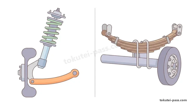
左右の車輪を1本の車軸でつないだ「車軸支持式(リジッド・アクスル式)」は強度が高くトラックなどに使われ、左右の車輪が別々に上下する「独立支持式(ストラット式など)」はばね下重量が軽く乗り心地が良いため乗用車に多く使われます。
A rigid axle suspension (connecting the left and right wheels with a single axle beam) offers high strength and is used on trucks, whereas an independent suspension (such as MacPherson strut, allowing each wheel to move vertically independently) has low unsprung weight and superior ride comfort, making it common on passenger cars.
スプリング(ばね)には、乗用車に多い「コイル・スプリング(巻きばね)」、トラックなどに使われ板間の摩擦で自身に減衰作用を持つ「リーフ・スプリング(重ね板ばね)」、ねじり反力を利用する「トーション・バー・スプリング」、大型バスなどに使われる「エア・スプリング(空気ばね)」があります。
Types of springs include coil springs (common on passenger cars), leaf springs (used on trucks, providing some self-damping through inter-leaf friction), torsion bar springs (utilizing twisting reaction force), and air springs (used on large buses and trucks).
コイル・スプリングには振動を止める減衰作用がないため、そのままでは車体がいつまでも上下に揺れ続けます。そこで「ショック・アブソーバ(shock absorber:ダンパ)」を併用し、ピストンが移動するときにオイルが小さな穴(オリフィス)やバルブを通る際の流動抵抗によって、ばねの上下振動を速やかに減衰(吸収)させます。
Because a coil spring has no damping action of its own, the vehicle would continue oscillating up and down indefinitely. Therefore, a shock absorber (damper) is paired with it, using the flow resistance of oil passing through small orifices and valves as a piston moves to rapidly dampen spring oscillations.
また、「スタビライザ(stabilizer:アンチロール・バー)」は、コの字形のばね鋼の棒で左右のサスペンション・アームをつないだ装置です。カーブ(旋回)時などで片側の車輪だけが沈み込んだときにバーがねじれ、そのねじり反力によって車体の傾き(ローリング)を抑えます。
A stabilizer (anti-roll bar) is a U-shaped spring-steel bar connecting the left and right suspension arms. When only one wheel compresses during cornering, the bar twists and uses its torsional reaction force to suppress body roll (tilting).
Key points
- 独立支持式サスペンションは左右の車輪が独立して動き、ばね下重量が軽く乗り心地や接地性に優れる
Independent suspension allows left and right wheels to move independently, reducing unsprung weight and improving ride comfort and road holding - ショック・アブソーバは、オイルがオリフィス(小孔)を通過するときの流動抵抗を利用してスプリングの上下振動を早期に減衰させる
A shock absorber uses hydraulic flow resistance as oil passes through orifices to quickly dampen up-and-down spring oscillations - スタビライザは棒のねじり反力を利用して旋回時の車体の傾き(ローリング)を抑える装置である(左右輪が同時に同じだけ上下するときは作用しない)
A stabilizer uses torsional reaction force to suppress vehicle body roll during cornering (it has no effect when both wheels move up or down equally)
| Word | Meaning |
|---|---|
| 独立支持式と車軸支持式 | Independent suspension and rigid axle suspension |
| コイル・スプリングとリーフ・スプリング | Coil spring and leaf spring |
| ショック・アブソーバ(shock absorber) | Shock absorber (damper) |
| スタビライザ(stabilizer) | Stabilizer (anti-roll bar) |
タイヤの表示・空気圧・摩耗と特異現象
Tire Markings, Air Pressure, Wear, and Special Tire Phenomena
タイヤの側面には「195/65R15 91H」のようにサイズが表示されています。
Tire size markings such as 195/65R15 91H are molded on the tire sidewall.
この場合、「195」はタイヤ断面幅 W(mm)、「65」はへん平率(%)、「R」はラジアル構造、「15」はホイールのリム径(インチ)、「91」はロード・インデックス(荷重指数)、「H」は走行可能な最高速度を示す速度記号です。へん平率は「(タイヤ断面高さ H ÷ 断面幅 W) × 100(%)」で求めます。
In this marking, 195 is the section width W (mm), 65 is the aspect ratio (%), R indicates radial construction, 15 is the wheel rim diameter (inches), 91 is the load index, and H is the speed symbol indicating maximum allowable speed. The aspect ratio is calculated as: (Section height H ÷ Section width W) × 100(%).
タイヤの空気圧が規定より「低すぎる」と、トレッドの両肩部(ショルダー部)が偏摩耗し、転がり抵抗が増えて燃費が悪化します。さらに空気圧不足のまま高速走行すると、タイヤが波打つように変形する「スタンディング・ウェーブ現象」が発生し、急激に発熱してバースト(破裂)する危険があります。
If tire inflation pressure is too low, both shoulder areas wear rapidly, rolling resistance increases, and fuel economy worsens. Furthermore, high-speed driving on underinflated tires causes a wavelike deformation called a standing wave phenomenon, generating intense heat that can lead to a tire burst.
逆に空気圧が規定より「高すぎる」と、トレッドの中央部(センタ部)が早く摩耗し、路面からの衝撃を吸収しにくくなって乗り心地が悪くなります。そのため、空気圧は走行前のタイヤが冷えている時にタイヤ・ゲージで測定・調整します。
Conversely, if inflation pressure is too high, the center of the tread wears prematurely and road shocks are poorly absorbed, hurting ride comfort. Therefore, check and adjust tire pressure with a tire gauge when the tires are cold before driving.
乗用車用タイヤの溝の深さの保安基準限度は「1.6 mm」であり、残り溝が 1.6 mm になると溝の底にある「スリップ・サイン」が現れます。
The legal safety limit for passenger car tire tread depth is 1.6 mm; when remaining groove depth wears down to 1.6 mm, wear indicators (slip signs) appear across the tread.
溝が減ったタイヤで水たまりのある道路を高速走行すると、排水が追いつかずタイヤが水膜の上に浮き上がり、ハンドルもブレーキも効かなくなる「ハイドロプレーニング現象」が起こりやすくなります。
Driving at high speed on wet roads with worn tread prevents water from escaping fast enough, causing the tire to float on a film of water so that both steering and braking become ineffective—a phenomenon called hydroplaning.
Key points
- タイヤ表示「195/65R15」は、断面幅 195 mm、へん平率 65%、ラジアル構造、リム径 15インチを表し、乗用車のタイヤ溝の使用限度(スリップ・サイン)は 1.6 mm である
195/65R15 means 195 mm width, 65% aspect ratio, Radial structure, and 15-inch rim; the passenger car tread depth limit (slip sign) is 1.6 mm - 空気圧が低すぎると両肩部(ショルダー)が摩耗して高速時にスタンディング・ウェーブ現象が起きやすく、高すぎると中央部(センタ)が摩耗する
Underinflation causes shoulder wear and high-speed standing wave phenomenon, while overinflation causes center tread wear - ハイドロプレーニング現象は、雨天高速走行時にタイヤが水膜の上に浮いて操縦・制動不能になる現象で、溝が減るほど起こりやすい
Hydroplaning occurs during high-speed wet driving when tires float on a water film and lose steering and braking control; worn tread makes it much more likely - 【例】タイヤ断面幅が 200 mm、断面高さが 120 mm のとき、へん平率 = (120 ÷ 200) × 100 = 60% となる
Example: When tire section width is 200 mm and section height is 120 mm, the aspect ratio = (120 ÷ 200) × 100 = 60%
| Word | Meaning |
|---|---|
| へん平率 | Aspect ratio (profile ratio) |
| スリップ・サイン(1.6 mm) | Tread wear indicator (slip sign: 1.6 mm) |
| スタンディング・ウェーブ現象 | Standing wave phenomenon |
| ハイドロプレーニング現象 | Hydroplaning phenomenon |
ホイール・アライメント(キャンバ・キャスタ・トーイン・キングピン傾角)
Wheel Alignment (Camber, Caster, Toe-in, and Kingpin Inclination)
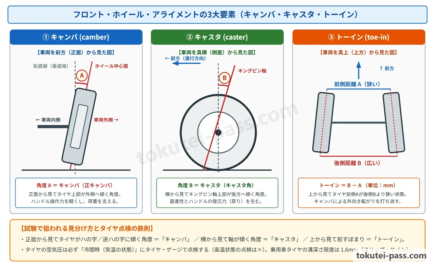
フロント・ホイール・アライメント(前輪整列)とは、ハンドルの操作を軽くし、直進安定性や旋回後の復元性を高め、タイヤの偏摩耗を防ぐために前輪に与えられた幾何学的な取付角度のことです。主な4要素は「キャンバ」「キャスタ」「キングピン傾角」「トーイン」です。
Front wheel alignment refers to the geometric mounting angles given to the front wheels to lighten steering effort, ensure straight-line stability and returnability after cornering, and prevent uneven tire wear. The four primary elements are camber, caster, kingpin inclination, and toe-in.
「キャンバ(camber)」は、車両を正面(前)から見たときのタイヤの上下方向の傾きです。
Camber is the vertical tilt of the front wheels when viewing the vehicle from the front.
上側が外に開いているものをプラス(正)キャンバといい、ハンドル操作力を軽くします。「キングピン傾角」は正面から見たキングピン軸の内側への傾きで、キャンバとともに路面での接地点との距離(スクラブ半径)を小さくして操作力を軽くし、直進への復元力を生みます。
Tilting the top of the wheel outward is called positive camber, which reduces steering effort. Kingpin inclination is the inward tilt of the kingpin (steering) axis when viewed from the front; together with camber, it reduces the scrub radius (kingpin offset) at the road surface to lighten steering effort and generate straight-ahead return force.
「キャスタ(caster)」は、車両を真横(側面)から見たときのキングピン軸(ストラット軸)の前後方向の傾きです。上側が後ろへ傾くプラス・キャスタによって、自転車のフロント・フォークと同じように前輪に「直進性(方向安定性)」と、カーブを曲がったあとにハンドルが元に戻ろうとする「復元力」を与えます。
Caster is the fore-and-aft tilt of the kingpin axis (strut axis) when viewing the vehicle from the side. Positive caster (tilted rearward at the top), like a bicycle front fork, imparts straight-line directional stability and self-centering returnability to the steering wheel after a turn.
「トーイン(toe-in)」は、車両を真上から見たとき、左右タイヤの前側の間隔 A が後ろ側の間隔 B よりも狭くなっている状態(B - A > 0)です。キャンバによってタイヤが外側へ転がろうとする力(キャンバ・スラスト)を打ち消し、タイヤの横滑りと偏摩耗を防ぐ役割があります。
Toe-in is the condition when viewing the vehicle from directly above where the front distance A between the left and right tires is narrower than the rear distance B (B - A > 0). It counteracts the outward rolling tendency caused by camber (camber thrust) to prevent sideslip and uneven tire wear.
Key points
- キャンバは車両を前から見たタイヤの傾きであり、キャスタは車両を横から見たキングピン軸の傾き(直進性とハンドル復元力を付与)である
Camber is wheel tilt viewed from the front, while caster is kingpin axis tilt viewed from the side (providing straight-line stability and steering returnability) - トーインは車両を上から見てタイヤの前側 A が後ろ側 B より狭い状態(トーイン=B-A)で、タイヤの横滑りと偏摩耗を防ぐ
Toe-in is when the front tire spacing A is narrower than the rear spacing B viewed from above (Toe-in = B - A), preventing sideslip and uneven wear - 【例】左右前輪タイヤの前側中心間距離 A が 1,446 mm、後ろ側中心間距離 B が 1,450 mm のとき、トーイン = 1,450 - 1,446 = 4 mm となる
Example: When the front center-to-center distance A between the front tires is 1,446 mm and the rear distance B is 1,450 mm, toe-in = 1,450 - 1,446 = 4 mm
| Word | Meaning |
|---|---|
| ホイール・アライメント(wheel alignment) | Wheel alignment |
| キャンバ(camber) | Camber |
| キャスタ(caster) | Caster |
| トーイン(toe-in) | Toe-in |
| キングピン傾角 | Kingpin inclination |
ステアリング(操縦装置)とパワー・ステアリング
Steering System and Power Steering
ステアリング装置は、運転者が回したステアリング・ホイール(ハンドル)の回転をステアリング・シャフトからステアリング・ギヤへ伝え、タイロッドやナックル・アームを介して前輪の向きを変える装置です。
The steering system transmits rotation of the steering wheel through the steering shaft to the steering gear, and then moves the tie rods and knuckle arms to change the direction of the front wheels.
乗用車には構造が簡単で軽量・高剛性な「ラック&ピニオン式」が多く使われ、トラックなどには大きな減速比が得られる「ボール・ナット式」が使われます。
Passenger cars widely use a simple, lightweight, high-rigidity rack-and-pinion steering gear, whereas trucks commonly use a ball-nut (recirculating-ball) steering gear capable of a large reduction ratio.
パワー・ステアリング(power steering)は、油圧または電動モータ(EPS)の力でハンドルの操作力を補助(アシスト)する装置です。電動式パワー・ステアリング(EPS)はエンジン停止時に油圧ポンプを回す必要がないため、エンジンの燃費向上に優れています。
Power steering uses hydraulic pressure or an electric motor (EPS) to assist the driver's steering effort. Electric power steering (EPS) does not need to drive a hydraulic pump when no steering assist is needed, offering superior fuel economy.
車速感応型パワー・ステアリングでは、駐車時の据え切りや低速走行時にはアシスト力を「大きく」してハンドルを軽く操作できるようにし、高速走行時にはアシスト力を「小さく」してハンドルに適度な重さ(手応え)を残し、直進安定性を高めています。
In speed-sensitive power steering, assist force is made large during parking (stationary steering) and low-speed driving to make the wheel easy to turn, and made small during high-speed driving to maintain firm steering feel and directional stability.
ステアリング・ホイールの点検では、直進位置でタイヤが動き始めるまでの「遊び(円周上で適正値内にあるか)」や、上下・左右に揺すったときの「緩み・ガタ」、およびタイロッド・エンドのボール・ジョイント・ブーツに破れがないかを確認します。
When inspecting the steering wheel, check steering wheel free play (rotational play at the rim from straight-ahead until the tires begin to move), looseness or play when shaken vertically and laterally, and inspect the tie-rod end ball joint boots for tears.
Key points
- ラック&ピニオン式ステアリングは、ピニオンの回転をラックの直線運動に直接変えるため、構造が簡単でハンドルの応答性が良い
Rack-and-pinion steering directly converts pinion rotation into linear rack motion, providing a simple structure and sharp steering response - パワー・ステアリングは、停車・低速走行時にはアシスト力(補助力)を大きくして操作を軽くし、高速走行時にはアシスト力を小さくして操縦安定性を保つ
Power steering provides large assist force when stopped or at low speed for light steering, and small assist force at high speed for stability - 電動式パワー・ステアリング(EPS)はトルク・センサと車速センサの信号に基づいてモータを制御し、油圧式に比べて燃費が良い
Electric power steering (EPS) controls a motor based on torque sensor and vehicle speed sensor signals, improving fuel efficiency compared to hydraulic systems
| Word | Meaning |
|---|---|
| ラック&ピニオン式 | Rack-and-pinion type |
| タイロッド(tie rod) | Tie rod |
| パワー・ステアリング(power steering) | Power steering |
| 据え切り | Stationary steering (turning wheels while stopped) |
油圧ブレーキの原理とドラム・ブレーキ/ディスク・ブレーキ
Hydraulic Brake Principles and Drum Brakes vs. Disc Brakes
油圧式ブレーキ(フット・ブレーキ)は、「密閉された容器内の液体の一点に加えられた圧力は、すべての方向に等しい強さで伝わる」という「パスカルの原理」を応用しています。ブレーキ・ブースタ(制動倍力装置)は、エンジンの吸気管負圧と大気圧の差を利用してペダル踏力を増大させます。
Hydraulic foot brakes apply Pascal's principle: pressure applied to an enclosed fluid is transmitted equally in all directions. A brake booster (vacuum servo) uses the pressure difference between engine intake manifold vacuum and atmospheric pressure to multiply pedal force.
マスタ・シリンダには、ピストンを2個直列に配置してブレーキ配管を2系統に分けた「タンデム・マスタ・シリンダ」が使われています。万一、片方の系統から液漏れが起きても、もう片方の系統で最低限の制動力を確保する安全設計になっています。
The master cylinder uses a tandem master cylinder with two pistons in series that split the brake lines into two independent hydraulic circuits. If a fluid leak occurs in one circuit, the other circuit still secures minimum braking force.
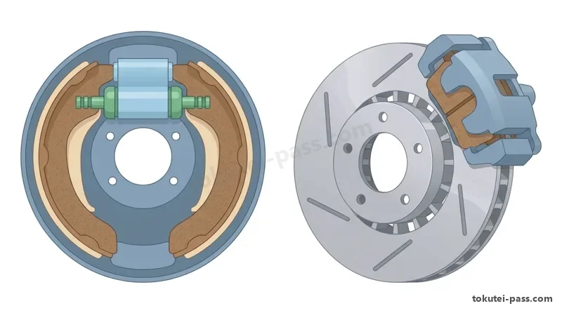
「ドラム・ブレーキ」は、ホイール・シリンダの油圧でブレーキシュー(ライニング)をドラムの内面に押し広げて制動します。回転するドラムにシューが食い込んで制動力が倍増する「自己倍力作用(セルフ・サーボ作用)」があるため大きな制動力が得られ、パーキング・ブレーキを組み込みやすい反面、熱がこもりやすい特徴があります。
A drum brake uses wheel cylinder hydraulic pressure to press brake shoes (with friction linings) outward against the inside of a rotating brake drum. Because the rotating drum wedges the leading shoe inward to multiply braking force—known as self-servo (self-energizing) action—it produces high braking force and easily incorporates a parking brake, but it tends to trap heat.
「ディスク・ブレーキ」は、回転するディスク・ロータをブレーキ・キャリパ内のピストンで両側からブレーキ・パッドで挟み付けて制動します。自己倍力作用はほとんどありませんが、ロータが外気にさらされているため放熱性が良く「フェード現象」が起きにくく、水に濡れても遠心力で飛ばされるため効きの回復が早い利点があります。
A disc brake uses pistons inside a brake caliper to clamp brake pads against both sides of a rotating disc rotor. Although it has almost no self-servo action, the exposed rotor dissipates heat well so fade rarely occurs, water is thrown off by centrifugal force for quick recovery when wet, and piston seal elasticity automatically adjusts pad-to-rotor clearance.
Key points
- 油圧ブレーキはパスカルの原理を利用しており、タンデム・マスタ・シリンダは2系統独立配管によって片系統液漏れ時にも制動力を確保する
Hydraulic brakes use Pascal's principle, and a tandem master cylinder uses two independent circuits to maintain braking if one circuit leaks - ドラム・ブレーキは自己倍力作用(セルフ・サーボ作用)があり拘束力が大きいが、熱がこもりやすい
Drum brakes have self-servo (self-energizing) action for strong braking force, but heat builds up easily inside the drum - ディスク・ブレーキは放熱性や水はけに優れてフェード現象や片効きが起きにくく、ピストン・シールの弾性変形でパッドのすき間を自動調整する
Disc brakes excel in heat dissipation and water shedding, resist fade and uneven pulling, and automatically adjust pad clearance via piston seal deformation
| Word | Meaning |
|---|---|
| パスカルの原理 | Pascal's principle |
| タンデム・マスタ・シリンダ | Tandem master cylinder |
| ブレーキ・ブースタ(制動倍力装置) | Brake booster (vacuum servo) |
| 自己倍力作用(セルフ・サーボ作用) | Self-servo (self-energizing) action |
| ブレーキ・キャリパとブレーキ・パッド | Brake caliper and brake pad |
フェード現象・ベーパ・ロック現象と停止距離・ABS
Fade Phenomenon, Vapor Lock, Stopping Distance, and ABS
長い下り坂などでフット・ブレーキを連続して使いすぎると、摩擦熱によってブレーキ・パッドやライニングが高温になり、摩擦係数が低下してブレーキの効きが悪くなります。これを「フェード現象(fade phenomenon)」といいます。
If the foot brake is used continuously on a long downgrade, frictional heat overheats the brake pads or linings, lowering their coefficient of friction and reducing braking effectiveness. This is called the fade phenomenon.
さらにブレーキの過熱が続くと、その熱がキャリパやホイール・シリンダ内のブレーキ液(ブレーキ・フルード)に伝わって沸騰し、配管内に気泡(ベーパ:蒸気)が発生します。
If brake overheating continues, the heat transfers to the brake fluid inside the caliper or wheel cylinder and causes it to boil, forming vapor bubbles in the brake lines.
するとペダルを踏んでも気泡が圧縮されるだけで油圧が伝わらず、ペダルがスカスカになってブレーキが効かなくなります。これを「ベーパ・ロック現象(vapor lock)」といい、防ぐには低速ギヤにシフトダウンしてエンジン・ブレーキを併用します。
When this happens, pressing the brake pedal merely compresses the vapor bubbles without transmitting hydraulic pressure, leaving the pedal spongy and the brakes ineffective. This is called vapor lock; to prevent both fade and vapor lock, downshift to a lower gear and use engine braking on long descents.
ABS(アンチロック・ブレーキ・システム)は、急ブレーキ時や滑りやすい路面での制動時に、車輪速センサでタイヤのロック(滑走)を検知して油圧を自動的に減圧・保持・増圧する装置です。車輪のロックを防ぐことで、車両の「方向安定性」を保ち、ハンドルを切って障害物を回避する「操舵性」を確保します。
ABS (Anti-lock Brake System) uses wheel speed sensors during sudden braking or braking on slippery roads to detect wheel lockup and automatically modulate (reduce, hold, and increase) brake fluid pressure. Preventing wheel lockup maintains directional stability and preserves steering control to steer around obstacles.
また、運転者が危険を感じてからブレーキが効き始めるまでに走る距離を「空走距離」、ブレーキが効き始めてから車が完全に止まるまでの距離を「制動距離」といい、両方を足したものが「停止距離(=空走距離+制動距離)」です。車速が2倍になると、空走距離は2倍、制動距離は2の2乗である「4倍」に延びます。
The distance traveled from when the driver perceives danger until the brakes begin to take effect is the reaction (free-running) distance, and the distance from when the brakes take effect until the vehicle stops completely is the braking distance; their sum is the stopping distance (Stopping distance = Reaction distance + Braking distance). Doubling vehicle speed doubles the reaction distance and quadruples (2 squared = 4 times) the braking distance.
Key points
- フェード現象はパッド・ライニングの過熱による摩擦力低下であり、ベーパ・ロック現象はブレーキ液が沸騰して気泡が生じ油圧が伝わらなくなる現象である
Fade is a drop in friction caused by overheated pads/linings, whereas vapor lock is loss of hydraulic pressure transmission caused by boiling brake fluid forming bubbles - ABSは急制動時の車輪ロックを防ぎ、車両の直進安定性とハンドルによる障害物回避能力(操舵性)を確保する
ABS prevents wheel lockup during hard braking to maintain straight-line directional stability and steering control around obstacles - 停止距離 = 空走距離 + 制動距離 であり、走行速度が2倍になると制動距離は4倍になる
Stopping distance = Reaction distance + Braking distance; when vehicle speed doubles, braking distance increases 4 times - 【例】空走距離が 15 m、制動距離が 25 m のとき、停止距離 = 15 + 25 = 40 m となる
Example: When the reaction distance is 15 m and the braking distance is 25 m, the stopping distance = 15 + 25 = 40 m
| Word | Meaning |
|---|---|
| フェード現象(fade) | Fade phenomenon |
| ベーパ・ロック現象(vapor lock) | Vapor lock phenomenon |
| ABS(アンチロック・ブレーキ・システム) | ABS (Anti-lock Brake System) |
| 空走距離・制動距離・停止距離 | Reaction distance, braking distance, and stopping distance |
駐車ブレーキ・大型車の補助ブレーキとブレーキ点検
Parking Brakes, Heavy-Duty Auxiliary Brakes, and Brake Inspection
駐車ブレーキ(パーキング・ブレーキ)は、駐車中に車両が動き出さないよう機械的なワイヤ・ケーブル(または電動アクチュエータ)で主に後輪を拘束する装置です。点検では、レバーまたはペダルを引いた(踏んだ)ときの「引き代(ノッチ数:カチカチという音の数)」が規定範囲内にあるかを確認します。
The parking brake uses a mechanical wire cable (or electric actuator) to lock mainly the rear wheels so a parked vehicle cannot roll. During inspection, pull the lever (or press the pedal) and verify that the travel (number of clicks/notches) is within specifications.
トラックやバスなどの大型車では、コンプレッサで作った圧縮空気の力でブレーキシューを作動させる「エア・ブレーキ(フル・エア・ブレーキ)」が用いられます。エア・タンクには凝縮した水が溜まるため、冬季の凍結やバルブの腐食を防ぐため毎日ドレン・コックから水抜きを行います。
Large trucks and buses use full air brakes powered by compressed air from an air compressor. Because condensed water collects in the air tanks, drain water daily from the drain cock to prevent freezing in winter and valve corrosion.
また、大型ジーゼル車が長い下り坂を走る際にフット・ブレーキの過熱を防ぐ補助ブレーキとして、「排気ブレーキ(エキゾースト・ブレーキ)」や「リターダ(電磁式・流体式)」が使われます。排気ブレーキは、排気管の途中にあるバルブを閉じてエンジンの排気抵抗を高め、強力なエンジン・ブレーキ力を発生させます。
Large diesel vehicles also use auxiliary brakes such as an exhaust brake or retarder to prevent foot-brake overheating on long downgrades. An exhaust brake closes a valve in the exhaust pipe to increase exhaust back-pressure and generate strong engine braking.
ブレーキ・ペダルの点検では、「遊び」と、ペダルを強く踏み込んだときの「床板とのすき間(踏み残し量)」、および踏み応えがフワフワする「スポンジー(エア混入)」がないかを確認します。
When inspecting the brake pedal, check pedal free play, pedal-to-floor clearance when depressed firmly, and ensure the pedal does not feel spongy (which indicates air trapped in the hydraulic lines).
ディスク・ブレーキではパッドが摩耗するとピストンが前に出た分だけリザーバ・タンクの液面が下がるため、液面の低下からパッドの摩耗や液漏れを推測できます。
On disc brakes, as the brake pads wear, the caliper pistons extend outward and the fluid level in the reservoir tank drops correspondingly, allowing pad wear or fluid leaks to be inferred from a low fluid level.
Key points
- 駐車ブレーキは機械式ケーブル等で車輪を固定し、レバーの引き代(ノッチ数)が適正か点検する
The parking brake holds the wheels mechanically via cable, and its lever travel (number of notches) is checked during inspection - 大型車の排気ブレーキは、エキゾースト・パイプ内のバルブを閉じて排気抵抗を高め、エンジン・ブレーキの効果を増大させる補助ブレーキである
An exhaust brake on a heavy vehicle closes a valve in the exhaust pipe to raise exhaust resistance and strengthen engine braking - ブレーキ配管に空気(エア)が混入するとペダルの踏み応えがフワフワ(スポンジー)になり、踏み込んだときの床板とのすき間が小さくなる
Air trapped in the brake lines makes the brake pedal feel spongy and reduces pedal-to-floor clearance when depressed
| Word | Meaning |
|---|---|
| 引き代(ノッチ数) | Lever travel (number of notches) |
| エア・ブレーキ(air brake) | Air brake |
| 排気ブレーキ(exhaust brake) | Exhaust brake |
| 床板とのすき間 | Pedal-to-floor clearance |
試験によく出るポイントと覚え方
Frequently Tested Points and Memory Tips
サスペンションとタイヤでは、「ショック・アブソーバ=ばねの上下振動を減衰」「スタビライザ=旋回時の車体の傾き(ローリング)を抑える」「空気圧不足=両肩摩耗・スタンディング・ウェーブ現象」「空気圧過大=中央摩耗」「溝不足(スリップ・サイン 1.6 mm)+雨天高速=ハイドロプレーニング現象」を正確に結び付けましょう。
For suspension and tires, match each pair accurately: Shock absorber = dampens vertical spring oscillation; Stabilizer = suppresses body roll in turns; Low tire pressure = shoulder wear + standing wave phenomenon; High tire pressure = center wear; Worn tread (1.6 mm slip sign) + high speed in rain = hydroplaning.
ホイール・アライメントは「どの方向から見たか」がポイントです。「前から見たタイヤの傾き=キャンバ」「前から見たキングピン軸の傾き=キングピン傾角」「横から見たキングピン軸の傾き=キャスタ(直進性と復元力)」「上から見た前後差=トーイン(後ろ B - 前 A)」です。
For wheel alignment, focus on the viewing direction: Tire tilt viewed from the front = Camber; Kingpin axis tilt viewed from the front = Kingpin inclination; Kingpin axis tilt viewed from the side = Caster (straight-line stability and returnability); Front-to-rear spacing difference viewed from above = Toe-in (Rear B - Front A).
パワー・ステアリングの引っ掛け問題では、「高速走行時ほどアシスト力を大きくする」という誤り選択肢がよく出ます。正しくは「低速・据え切り時はアシスト大(軽くする)、高速時はアシスト小(安定させる)」です。
A common power-steering trap question claims that assist force is increased at high speeds. In fact, assist force is large at low speeds/parking (for light effort) and small at high speeds (for stability).
ブレーキでは、「フェード現象=摩擦材(パッド・ライニング)の過熱」「ベーパ・ロック現象=ブレーキ液の沸騰・気泡発生」の違いと、「ドラム=自己倍力作用あり・熱がこもる」「ディスク=放熱性良好・フェードに強い・すき間自動調整」の対比を暗記してください。
For brakes, memorize the difference between Fade = overheated friction material (pads/linings) and Vapor lock = boiling brake fluid creating vapor bubbles, and contrast Drum brakes = self-servo action but retains heat vs. Disc brakes = good cooling, fade-resistant, and automatic clearance adjustment.
Key points
- ショック・アブソーバ=上下振動の減衰 / スタビライザ=旋回時のローリング抑制 / スリップ・サイン=残り溝 1.6 mm
Shock absorber = dampens vertical oscillation / Stabilizer = suppresses body roll / Slip sign = 1.6 mm remaining tread depth - 空気圧不足=両肩摩耗・スタンディング・ウェーブ現象 / 雨天高速の水膜浮き上がり=ハイドロプレーニング現象
Low tire pressure = shoulder wear & standing wave / Floating on water film at high speed in rain = hydroplaning - キャンバ=前から見たタイヤ傾き / キャスタ=横から見た軸傾き(直進・復元性) / トーイン=上から見て後ろB-前A
Camber = tire tilt from front / Caster = axis tilt from side (stability & return) / Toe-in = viewed from above (Rear B - Front A) - パワー・ステアリングは低速時にアシスト力を大きくし、高速時にはアシスト力を小さくする
Power steering provides large assist force at low speed and small assist force at high speed - フェード=摩擦材過熱 / ベーパ・ロック=ブレーキ液沸騰・気泡発生 / ディスク・ブレーキ=放熱良好でフェードが起きにくい
Fade = overheated friction pads/linings / Vapor lock = boiling brake fluid bubbles / Disc brake = good cooling and fade resistance
| Word | Meaning |
|---|---|
| ローリング(rolling) | Body rolling |
| 偏摩耗 | Uneven tire wear |
| スポンジー(spongy) | Spongy brake pedal |
Running Gear, Steering & Brakes
Practice this chapter in the appOfficial references
- 一般社団法人 日本自動車整備振興会連合会(JASPA)「自動車整備分野特定技能評価試験 学習用テキスト(三級自動車整備士講習用テキスト準拠)」 — https://www.jaspa.or.jp/
- 国土交通省 物流・自動車局「自動車整備分野特定技能1号評価試験 試験実施要領」 — https://www.mlit.go.jp/jidosha/jidosha_fr10_000041.html