
Maintenance Testing Machines, Measuring Instruments, and Tools
整備用の試験機・計量器・工具
Automobile Maintenance · 自動車整備分野 · Written by Tokutei Pass based on the official study texts; not copied verbatim.
ノギス(vernier caliper)の構造と目盛りの読み方
Structure and Scale Reading of the Vernier Caliper
ノギス(vernier caliper)は、1台で部品の「外径(外側寸法)」「内径(内側寸法)」「深さ(デプス)」「段差」の4種類を測定できる計量器です。外径はジョウ(外側用測定面)、内径はクチバシ(内側用測定面)、深さはデプス・バーを使って測ります。
A vernier caliper is a measuring instrument that can measure 4 types of part dimensions with a single tool: outside diameter (external dimension), inside diameter (internal dimension), depth, and step. Outside diameter is measured using the outside jaws, inside diameter using the inside beaks, and depth using the depth bar.
自動車整備でよく使われる標準的なノギスの最小読み取り値(最小目盛り)は「0.05 mm(1/20 mm)」です。本尺(主尺)は 1 mm 単位で刻まれており、スライダ側の副尺(バーニヤ目盛り)は本尺の 19 mm(または 39 mm)を20等分して 0.05 mm 単位を読み取れるようになっています。
The minimum reading value (least count) of a standard vernier caliper commonly used in automotive maintenance is 0.05 mm (1/20 mm). The main scale is graduated in 1 mm increments, while the vernier scale on the slider divides 19 mm (or 39 mm) of the main scale into 20 equal parts so that 0.05 mm increments can be read.
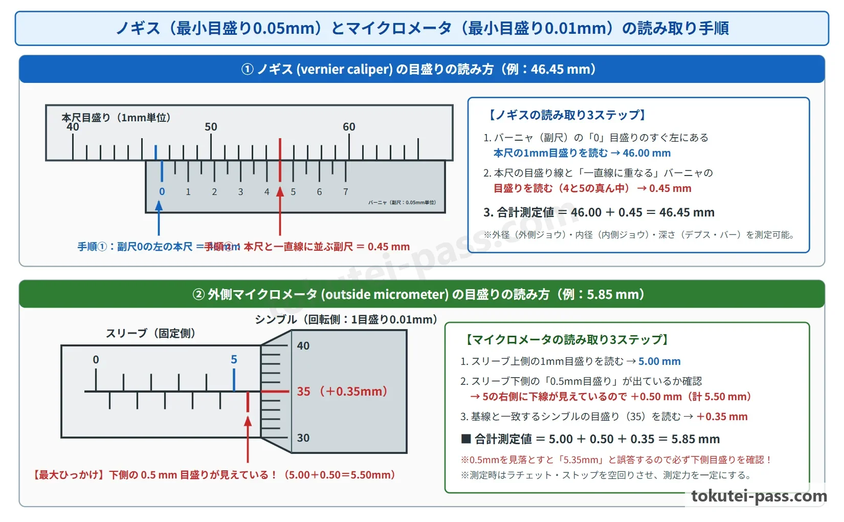
ノギスの目盛りを読む手順は次の2ステップです。ステップ①:まず副尺の「0(ゼロ)の線」が指している位置のすぐ左側にある本尺の目盛りを「1 mm 単位(整数 mm)」で読みます。
The procedure for reading a vernier caliper scale consists of two steps. Step 1: First, read the main scale graduation immediately to the left of the zero (0) line on the vernier scale in 1 mm increments (whole mm).
ステップ②:次に、副尺の目盛り線と本尺の目盛り線が「まっすぐ一直線に一致しているところ」を探し、その位置の副尺の数値を「0.05 mm 単位(小数 mm)」として読み取ります。最後にステップ①の本尺値とステップ②の副尺値を足し合わせます。
Step 2: Next, find where a graduation line on the vernier scale aligns in a straight line with a graduation line on the main scale, and read the vernier scale value at that position in 0.05 mm increments (decimal mm). Finally, add the main scale value from Step 1 and the vernier scale value from Step 2 together.
Key points
- ノギスは1台で「外径」「内径」「深さ」「段差」の4つを測定でき、一般的な最小読み取り値は 0.05 mm である
A single vernier caliper can measure outside diameter, inside diameter, depth, and step, and its typical minimum reading is 0.05 mm - 読み方:①副尺の「0」線のすぐ左の本尺目盛り(1 mm 単位)を読む → ②本尺と一直線に重なる副尺目盛り(0.05 mm 単位)を読んで足す
How to read: (1) Read the main scale graduation just to the left of the vernier 0 line (1 mm unit) -> (2) Read the vernier graduation aligned with the main scale (0.05 mm unit) and add them - 測定物はジョウの先端ではなくできるだけ根元(本尺に近い奥側)で直角に挟み、目盛りは正面から読み取る
Hold the object perpendicular to the jaws as close to the base (near the main scale) as possible rather than at the tips, and read the scale from directly in front - 【例】副尺の「0」線が本尺の 46 mm と 47 mm の間にあり、副尺の「4.5(0.45 mm)」の線が本尺と一致しているとき、測定値 = 46 + 0.45 = 46.45 mm となる
Example: When the vernier 0 line is between 46 mm and 47 mm on the main scale and the 4.5 (0.45 mm) vernier line aligns with the main scale, measured value = 46 + 0.45 = 46.45 mm - 【例】副尺の「0」線が本尺の 12 mm をわずかに過ぎ、副尺の「3.0(0.30 mm)」の線が本尺と一致しているとき、測定値 = 12 + 0.30 = 12.30 mm となる
Example: When the vernier 0 line is slightly past 12 mm on the main scale and the 3.0 (0.30 mm) vernier line aligns with the main scale, measured value = 12 + 0.30 = 12.30 mm
| Word | Meaning |
|---|---|
| ノギス(vernier caliper) | Vernier caliper (Measures outside diameter, inside diameter, depth, and step to 0.05 mm) |
| 本尺(主尺)と副尺(バーニヤ) | Main scale and vernier scale (The main scale reads 1 mm units and the vernier scale reads 0.05 mm units) |
| デプス・バー(depth bar) | Depth bar (Bar extending from the end of the caliper used to measure hole or groove depth) |
| 最小読み取り値(0.05 mm) | Minimum reading value (0.05 mm) (Smallest measurement increment on a standard vernier caliper) |
マイクロメータ(micrometer)の使い方と目盛りの読み方
How to Use and Read a Micrometer
アウトサイド・マイクロメータ(外側マイクロメータ)は、ピストン外径やクランク・ジャーナル径、ブレーキ・ディスク厚さなどを「0.01 mm(1/100 mm)」単位で精密に測定する計量器です。測定範囲ごとに 0〜25 mm 用、25〜50 mm 用、50〜75 mm 用などに分かれています。
An outside micrometer is a precision measuring instrument that measures piston outside diameter, crank journal diameter, or brake disc thickness in 0.01 mm (1/100 mm) increments. Micrometers are divided by measurement range, such as 0~25 mm, 25~50 mm, and 50~75 mm.
使う前には必ずアンビルとスピンドルの測定面を清掃し、0〜25 mm 用は両測定面を直接合わせ、25 mm 以上のものは「基準棒(テスト・バー)」を挟んで「0(ゼロ)点点検(基準点合わせ)」を行います。
Before use, always clean the measuring faces of the anvil and spindle; for a 0~25 mm micrometer, bring both faces directly together, and for 25 mm or larger, place a standard test bar between them to perform a zero-point check (zero adjustment).
測定物にスピンドルを当てるときは、一定の測定圧にするため「ラチェット・ストップ」を空転(カチカチと2〜3回)させて止めます。
When bringing the spindle into contact with the workpiece, turn the ratchet stop until it clicks idly (2 to 3 clicks) to ensure a constant measuring pressure.
目盛りの構造は、固定された「スリーブ(sleeve)」の基準線の上側に 1 mm 刻みの目盛り、下側に 0.5 mm 刻みの半目盛りがあり、回転する「シンブル(thimble)」の円周には 0.5 mm を50等分した「1目盛り = 0.01 mm」の目盛りが刻まれています。
In the scale structure, the fixed sleeve has 1 mm graduations above the datum line and 0.5 mm half-graduations below it, while the rotating thimble has graduations dividing 0.5 mm into 50 equal parts around its circumference (1 graduation = 0.01 mm).
読み方の手順は3ステップです。ステップ①:スリーブの上側目盛りで 1 mm 単位を読みます。
The reading procedure has 3 steps. Step 1: Read the 1 mm increment on the upper scale of the sleeve.
ステップ②:スリーブの下側にある「0.5 mm の補助目盛り線」が見えているかどうかを確認します(見えていれば +0.50 mm、隠れていれば 0.00 mm)。ステップ③:スリーブの横基準線と一致しているシンブルの目盛りを「0.01 mm 単位」で読み、すべてを足し合わせます。
Step 2: Check whether the 0.5 mm sub-graduation line on the lower side of the sleeve is visible (+0.50 mm if visible, 0.00 mm if hidden). Step 3: Read the thimble graduation that aligns with the horizontal datum line of the sleeve in 0.01 mm increments, and add all values together.
Key points
- マイクロメータの最小目盛りは 0.01 mm であり、使用前に必ず基準棒等で0点点検を行い、測定時はラチェット・ストップを回して測定圧を一定にする
The minimum graduation of a micrometer is 0.01 mm; always check the zero point with a test bar before use, and turn the ratchet stop during measurement to keep measuring pressure constant - 読み方:①スリーブ上目盛り(1 mm)+ ②スリーブ下目盛り(0.5 mm 線が見えていれば 0.50 mm)+ ③シンブル目盛り(0.01 mm)
How to read: (1) Upper sleeve scale (1 mm) + (2) Lower sleeve scale (0.50 mm if the 0.5 mm line is visible) + (3) Thimble scale (0.01 mm) - スリーブ下側の「0.5 mm 目盛り線」の見落としが試験で最も多いミスなので必ず確認する
Overlooking the 0.5 mm graduation line on the lower sleeve is the most common mistake on the exam, so always check it carefully - 【例】0〜25 mm 用マイクロメータで、スリーブ上目盛りが 5 mm、下側の 0.5 mm 線が見えており、シンブルが 35(0.35 mm)を指しているとき、測定値 = 5 + 0.50 + 0.35 = 5.85 mm となる
Example: With a 0~25 mm micrometer, if the upper sleeve reads 5 mm, the lower 0.5 mm line is visible, and the thimble points to 35 (0.35 mm), measured value = 5 + 0.50 + 0.35 = 5.85 mm - 【例】50〜75 mm 用マイクロメータで、スリーブが 12.0 mm(下の 0.5 mm 線は見えず)、シンブルが 18(0.18 mm)のとき、測定値 = 50 + 12.0 + 0.18 = 62.18 mm となる
Example: With a 50~75 mm micrometer, if the sleeve reads 12.0 mm (lower 0.5 mm line not visible) and the thimble reads 18 (0.18 mm), measured value = 50 + 12.0 + 0.18 = 62.18 mm
| Word | Meaning |
|---|---|
| アウトサイド・マイクロメータ(outside micrometer) | Outside micrometer (Precision tool measuring external dimensions in 0.01 mm increments) |
| スリーブ(sleeve)とシンブル(thimble) | Sleeve and thimble (The fixed barrel (sleeve) and rotating barrel (thimble) containing the scale markings) |
| ラチェット・ストップ(ratchet stop) | Ratchet stop (Knob at the end of the micrometer that limits and equalizes spindle contact pressure) |
| 基準棒(テスト・バー) | Standard bar (test bar) (Reference rod used for zero-point calibration on micrometers of 25 mm or larger) |
ダイヤル・ゲージ(dial gauge)の読み方と曲がり計算
Reading a Dial Gauge and Calculating Shaft Bend
ダイヤル・ゲージ(dial gauge)は、測定子(スピンドル)のわずかな上下動を歯車で拡大して指針の回転に変える計量器です。マグネット・スタンドで固定し、シャフトの曲がり(振れ)、ディスク・ロータの振れ、ギヤのバックラッシュ(歯面のすき間)、軸方向の遊び(スラスト・クリアランス)などを測定します。
A dial gauge is a measuring instrument that magnifies slight vertical movements of the contact plunger (spindle) through gears into pointer rotation. Fixed on a magnetic stand, it measures shaft bend (runout), disc rotor runout, gear backlash (tooth clearance), and axial play (thrust clearance).
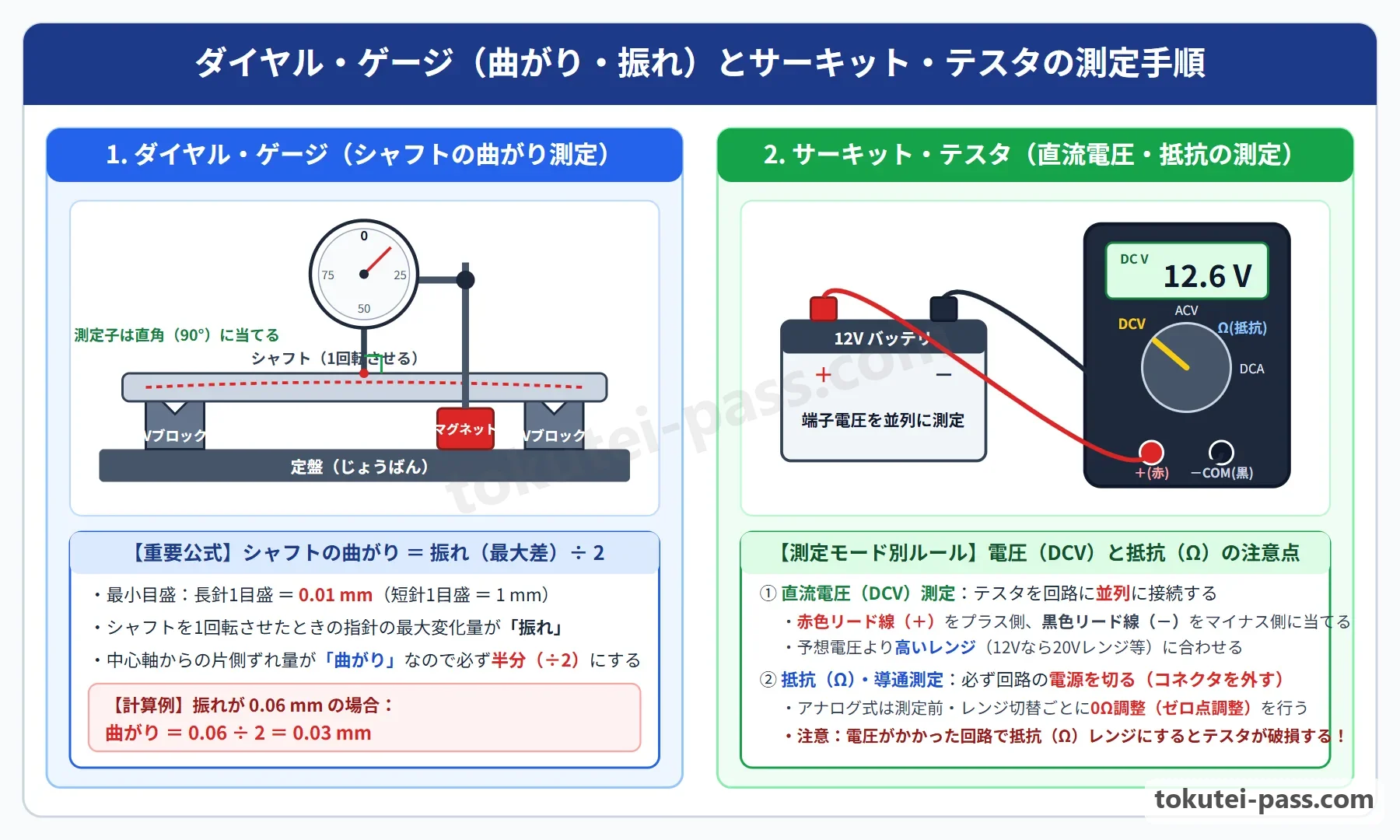
ダイヤル・ゲージの文字板には、内側の「短針(1目盛り = 1 mm)」と外側の「長針(1目盛り = 0.01 mm、1回転 = 1.00 mm)」があります。測定する面に対して、測定子は必ず「直角(90°)」に当て、外枠ベゼルを回して長針を「0」に合わせてから測定を開始します。
The dial face has an inner short hand (1 graduation = 1 mm) and an outer long hand (1 graduation = 0.01 mm, 1 revolution = 1.00 mm). Always place the spindle perpendicular (90 degrees) to the surface being measured, and rotate the outer bezel to align the long hand with 0 before starting measurement.
Vブロックの上にシャフトを載せ、中央部にダイヤル・ゲージを当ててシャフトをゆっくり1回転させたとき、長針が動いた最大値と最小値の差を「振れ(runout:全振れ)」といいます。
When a shaft is placed on V-blocks, a dial gauge is applied to its center, and the shaft is slowly rotated 1 full turn, the difference between the maximum and minimum readings of the long hand is called runout (total indicator reading).
ここで試験における超重要ルールがあります。シャフトが中心軸から片側に「曲がり」の分だけずれていると、1回転させたときにゲージの針は上方向と下方向の両方に振れるため、振れ幅は曲がりの2倍になります。したがって、「シャフトの曲がり = 振れ(最大差) ÷ 2」で必ず半分にして求めます。
Here lies a super-important rule for the exam. When a shaft is bent away from its center axis by the amount of bend, rotating it 1 turn causes the gauge pointer to deflect both upward and downward, making total runout twice the actual bend. Therefore, always divide by two: Shaft bend = Runout (maximum difference) / 2.
Key points
- ダイヤル・ゲージは長針1目盛りが 0.01 mm(1回転=1 mm)、短針1目盛りが 1 mm であり、測定子は被測定面に直角(90°)に当てる
On a dial gauge, 1 graduation of the long hand is 0.01 mm (1 turn = 1 mm) and 1 graduation of the short hand is 1 mm; apply the spindle perpendicular (90 degrees) to the measured surface - Vブロック上でシャフトを1回転させたとき、「シャフトの曲がり = ダイヤル・ゲージの振れ(最大値-最小値)÷ 2」で計算する
When rotating a shaft 1 turn on V-blocks, calculate using: Shaft bend = Dial gauge runout (Maximum value - Minimum value) / 2 - ディスク・ロータの振れやフライホイールの面振れは、そのまま「振れ(最大差)」として読み、シャフトの「曲がり」を問われたときは2で割る
Read disc rotor runout or flywheel face runout directly as runout (maximum difference), and divide by 2 when asked for the bend of a shaft - 【例】Vブロック上のシャフトを1回転させたとき、ダイヤル・ゲージの指針が 0 mm から 0.06 mm まで振れた場合、振れは 0.06 mm、シャフトの曲がりは 0.06 ÷ 2 = 0.03 mm となる
Example: When a shaft on V-blocks is rotated 1 turn and the dial gauge pointer moves from 0 mm to 0.06 mm, the runout is 0.06 mm and the shaft bend is 0.06 / 2 = 0.03 mm - 【例】指針の最小値が -0.02 mm、最大値が +0.08 mm だった場合、振れ = 0.08 - (-0.02) = 0.10 mm、シャフトの曲がり = 0.10 ÷ 2 = 0.05 mm となる
Example: When the minimum pointer reading is -0.02 mm and the maximum reading is +0.08 mm, runout = 0.08 - (-0.02) = 0.10 mm, and shaft bend = 0.10 / 2 = 0.05 mm
| Word | Meaning |
|---|---|
| ダイヤル・ゲージ(dial gauge) | Dial gauge (Precision indicator measuring runout, backlash, and play in 0.01 mm increments) |
| Vブロックと定盤 | V-blocks and surface plate (Precision supports used to hold cylindrical shafts while measuring runout) |
| 振れ(runout)と曲がり(bend) | Runout and bend (Shaft bend is always half of the total runout measured on V-blocks) |
| バックラッシュ(backlash) | Backlash (Clearance between meshing gear teeth measured with a dial gauge) |
サーキット・テスタ(circuit tester)の使い方と注意点
How to Use a Circuit Tester and Precautions
サーキット・テスタ(マルチ・メータ)は、電気回路の「直流電圧(DCV)」「交流電圧(ACV)」「抵抗(Ω:オーム)・導通」「直流電流(DCA)」などを測定する試験機です。赤色のテスト・リードをプラス(+)端子に、黒色のテスト・リードをマイナス(-/COM)端子に差し込んで使います。
A circuit tester (multimeter) is a testing instrument that measures direct current voltage (DCV), alternating current voltage (ACV), resistance (Ω: ohms) / continuity, and direct current (DCA) in electrical circuits. Insert the red test lead into the positive (+) terminal and the black test lead into the negative (- / COM) terminal.
① 直流電圧(DCV)を測るとき:ロータリ・スイッチを「DCV(直流電圧)」の、予想される電圧よりも「1段高いレンジ」(12 Vバッテリなら 20 Vや 50 Vレンジなど)に合わせます。そして測定したい部位にテスタを「並列」に接続し、赤色リードをプラス側、黒色リードをマイナス(ボデー・アース)側に当てます。
(1) When measuring DC voltage (DCV): Set the rotary switch to a DCV range one step higher than the expected voltage (such as the 20 V or 50 V range for a 12 V battery). Connect the tester in parallel with the part to be measured, touching the red lead to the positive side and the black lead to the negative (body ground) side.
② 抵抗(Ω)や導通を測るとき:内蔵電池から微弱な電流を流して測定するため、必ず回路のスイッチをOFFにするかコネクタを外し、「電圧がかかっていない状態」で測定します。電圧がかかった回路に抵抗レンジで当てると、テスタのヒューズが切れたり内部が破損したりします。
(2) When measuring resistance (Ω) or continuity: Because the tester sends a weak current from its internal battery to measure resistance, always turn the circuit switch OFF or disconnect the connector so measurement is performed with no voltage applied. Applying the resistance range to a live circuit will blow the tester fuse or damage its internals.
また、アナログ式サーキット・テスタで抵抗(Ω)を測定するときは、測定前およびレンジを切り替えるごとに、赤と黒のテスト・リード先端をショート(接触)させて指針が「0 Ω」を指すように「0 Ω調整(ゼロ点調整)」を行います。なお、電流(DCA)を測るときはテスタを回路に「直列」に接続します。
Furthermore, when measuring resistance (Ω) with an analog circuit tester, before measuring and every time you change the range, touch (short) the tips of the red and black test leads together and perform 0 Ω adjustment (zero-point adjustment) so the pointer reads 0 Ω. Note that when measuring current (DCA), connect the tester in series with the circuit.
Key points
- 電圧(DCV)測定では、予想電圧より高いレンジを選び、回路に「並列」に赤リード(+)・黒リード(-)を当てる(電流測定は「直列」につなぐ)
For voltage (DCV) measurement, select a range higher than the expected voltage and connect the red (+) and black (-) leads in parallel with the circuit (connect in series for current measurement) - 抵抗(Ω)測定では、テスタ破損を防ぐため必ず回路の電源を切り(コネクタを外し)、電圧がかかっていない状態で測定する
For resistance (Ω) measurement, always turn OFF circuit power (disconnect the connector) to measure with no voltage applied and prevent damaging the tester - アナログ式テスタで抵抗(Ω)を測るときは、測定前やレンジ変更のたびに赤・黒リードを接触させて「0 Ω調整」を行う
When measuring resistance (Ω) with an analog tester, touch the red and black leads together to perform 0 Ω adjustment before measurement and whenever changing the range
| Word | Meaning |
|---|---|
| サーキット・テスタ(circuit tester) | Circuit tester (multimeter) (Instrument for measuring voltage, resistance, continuity, and current) |
| 直流電圧(DCV)と抵抗(Ω) | DC voltage (DCV) and resistance (Ω) (DCV is measured in parallel on a live circuit; Ω is measured with power OFF) |
| 0 Ω調整(ゼロ点調整) | 0 Ω adjustment (zero adjustment) (Calibrating an analog ohmmeter by shorting the leads before measuring resistance) |
| 導通点検 | Continuity check (Testing whether an electrical path is complete or has an open circuit) |
シックネス・ゲージ・プラスチゲージ・各種専用試験機
Thickness Gauge, Plastigage, and Special-Purpose Testers
シックネス・ゲージ(thickness gauge:すき間ゲージ)は、精密な厚みの薄い鋼板(リーフ)を束ねた計量器です。
A thickness gauge (feeler gauge) is a measuring tool consisting of a bundle of thin steel blades (leaves) of precise thicknesses.
エンジンのバルブ・クリアランス(バルブすき間)やピストン・リングの合口すき間、スパーク・プラグのギャップ、およびストレート・エッジ(直定規)と組み合わせたシリンダ・ヘッド下面の平面度(ひずみ)測定に使います。
It is used to measure engine valve clearance, piston ring end gap, spark plug gap, and—when combined with a precision straight edge—the flatness (warpage) of the cylinder head lower surface.
プラスチゲージ(plastigage)は、柔らかいプラスチックの細い糸状ゲージです。クランク・ジャーナルやクランク・ピンに載せてベアリング・キャップを規定トルクで締め付け、再び外したときにプラスチックが押しつぶされた「幅」を専用スケールと比較することで、ベアリングの「オイル・クリアランス(油すき間)」を測定します。
Plastigage is a thin, soft plastic thread gauge. By placing it on a crankshaft journal or crankpin, tightening the bearing cap to the specified torque, removing the cap again, and comparing the crushed width of the plastic strip against its dedicated scale, you measure the bearing oil clearance.
コンプレッション・ゲージ(compression gauge)は、エンジンの圧縮圧力を測定する試験機です。エンジンを暖機したあと全気筒のスパーク・プラグを取り外し、燃料噴射を止め、プラグ・ホールにゲージを取り付けてアクセル・ペダルを全開(スロットル全開)にし、スタータでエンジンを規定回転速度で回して測定します。
A compression gauge is a tester that measures engine compression pressure. After warming up the engine, remove the spark plugs from all cylinders, cut off fuel injection, attach the gauge to a spark plug hole, fully depress the accelerator pedal (wide-open throttle), and crank the engine with the starter at the specified speed to measure.
また、バッテリの比重計(ハイドロメータ)は、ガラス管内に電解液を吸い上げて浮き子(フロート)の目盛りを読みます。
Additionally, a battery hydrometer draws electrolyte into a glass tube to read the scale on the internal float.
このとき、表面張力で盛り上がった縁ではなく、水平な液面(メニスカスの下端)を真横(目の高さ)から読み取ります。タイミング・ライトは1番気筒の点火信号に同期してストロボ発光させ、クランク・プーリの合いマークを照らして点火時期を点検します。
When doing so, read the horizontal liquid level (bottom of the meniscus) straight from the side at eye level, rather than the outer edge raised by surface tension. A timing light flashes a strobe in sync with the #1 cylinder ignition signal to illuminate the timing marks on the crank pulley and check ignition timing.
Key points
- シックネス・ゲージはバルブ・クリアランスやピストン・リング合口すき間を測り、ストレート・エッジと併用してシリンダ・ヘッドの平面度(ひずみ)を測定する
A thickness gauge measures valve clearance and piston ring end gap, and is used with a straight edge to measure cylinder head flatness (warpage) - プラスチゲージは、ベアリング・キャップを規定トルクで締めたときにつぶれたゲージの幅から、クランクシャフト等のオイル・クリアランスを測定する
Plastigage measures crankshaft bearing oil clearance from the crushed width of the plastic strip after tightening the bearing cap to specified torque - コンプレッション・ゲージで圧縮圧力を測るときは、暖機後に全気筒のスパーク・プラグを外し、スロットル・バルブを全開にしてスタータを回す
When measuring compression pressure with a compression gauge, warm up the engine, remove all spark plugs, hold the throttle valve wide open, and crank with the starter
| Word | Meaning |
|---|---|
| シックネス・ゲージ(thickness gauge) | Thickness gauge (feeler gauge) (Calibrated metal strips used to measure narrow gaps and clearances) |
| ストレート・エッジ(straight edge) | Straight edge (Precision flat bar used with a thickness gauge to check cylinder head warpage) |
| プラスチゲージ(plastigage) | Plastigage (Deformable plastic thread used to measure bearing oil clearance) |
| コンプレッション・ゲージ(compression gauge) | Compression gauge (Pressure gauge threaded into the spark plug hole to test cylinder compression) |
| タイミング・ライト(timing light) | Timing light (Strobe light synchronized with cylinder #1 ignition to check ignition timing marks) |
トルク・レンチ(torque wrench)と締付けトルクの計算
Torque Wrench and Tightening Torque Calculation
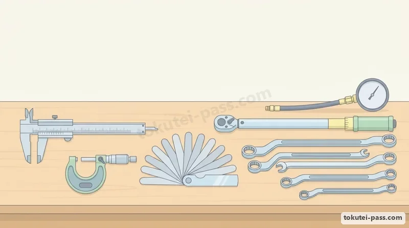
トルク・レンチ(torque wrench)は、シリンダ・ヘッド・ボルトやホイール・ナットなどの重要なボルト・ナットを、規定された締付けトルク(回転力)で正確に締め付けるための計量工具です。
A torque wrench is a measuring tool used to accurately tighten critical bolts and nuts—such as cylinder head bolts and wheel nuts—to their specified tightening torque (rotational force).
指針でトルクを読み取る「プレート形(ビーム形)」や、設定トルクに達すると「カチッ」と音と手応えで知らせる「プリセット形」があります。
Common types include the plate (beam) type, where torque is read on a pointer scale, and the preset (click) type, which alerts the user with a click sound and feel when the set torque is reached.
トルク(T)とは「ボルト中心からの距離(腕の長さ L)× 直角に加える力(F)」であり、国際単位(SI単位)では「N・m(ニュートン・メートル)」を使います。
Torque (T) is defined as Distance from the bolt center (lever arm length L) × Force applied at a right angle (F), and uses the SI unit N·m (newton-meter).
たとえば長さ 0.5 m のレンチに 100 N の力を直角にかけると、締付けトルクは 100 × 0.5 = 50 N・m になります(旧単位 1 kgf・m は約 9.8 N・m です)。
For example, applying a force of 100 N at a right angle to a wrench 0.5 m long produces a tightening torque of 100 × 0.5 = 50 N·m (the old unit 1 kgf·m is approximately 9.8 N·m).
トルク・レンチを使うときは、まずソケット・レンチなどで仮締めを行い、最終的な本締めにのみトルク・レンチを使います。固く締まったボルトを緩めるためにトルク・レンチを使ったり、パイプを継ぎ足して使ったりすると、精度が狂ったり破損したりするため厳禁です。
When using a torque wrench, first perform temporary snug tightening with a socket wrench, and use the torque wrench only for final tightening. Using a torque wrench to loosen tightly seized bolts or extending the handle with a pipe is strictly prohibited, as it ruins accuracy or damages the tool.
また、プリセット形トルク・レンチは使用後にそのまま放置すると内蔵スプリングがへたって誤差が生じるため、使用後は必ず目盛りを「最低トルク値」に戻して保管します(目盛り範囲以下に緩めすぎないこと)。
Furthermore, leaving a preset-type torque wrench wound up after use causes the internal spring to fatigue and lose accuracy; therefore, always return the scale to its lowest torque setting before storing (do not loosen it below the minimum scale range).
Key points
- トルク T(N・m) = 力 F(N) × 中心からの距離 L(m) であり、1 kgf・m = 約 9.8 N・m(概算で約 10 N・m)である
Torque T(N·m) = Force F(N) × Distance from center L(m), and 1 kgf·m is approximately 9.8 N·m (roughly 10 N·m) - トルク・レンチは最終の本締めに使い、ボルトを緩める作業には使わない(プリセット形は使用後に最低目盛りへ戻して保管する)
Use a torque wrench only for final tightening, never for loosening bolts (return a preset torque wrench to its minimum scale setting for storage after use) - 【例】有効長(グリップ中心までの長さ)が 0.4 m のトルク・レンチに 250 N の力を直角に加えたとき、締付けトルク T = 250 × 0.4 = 100 N・m となる
Example: When a force of 250 N is applied perpendicular to a torque wrench with an effective length (to the grip center) of 0.4 m, tightening torque T = 250 × 0.4 = 100 N·m - 【例】規定締付けトルクが 60 N・m のボルトを、有効長 0.3 m のトルク・レンチで締めるとき、必要な力 F = 60 ÷ 0.3 = 200 N となる
Example: When tightening a bolt with a specified torque of 60 N·m using a torque wrench with an effective length of 0.3 m, required force F = 60 / 0.3 = 200 N
| Word | Meaning |
|---|---|
| トルク・レンチ(torque wrench) | Torque wrench (Precision wrench used to apply a specific torque to a fastener) |
| プレート形とプリセット形 | Plate (beam) type and preset (click) type (Two main types of torque wrenches used in automotive maintenance) |
| N・m(ニュートン・メートル) | N·m (newton-meter) (SI unit of torque equal to force in newtons multiplied by lever length in meters) |
| 仮締めと本締め | Temporary tightening and final tightening (Snugging fasteners first with a standard wrench before final torqueing) |
一般手工具と動力工具(グラインダ・インパクト・レンチ)の取扱い
Handling General Hand Tools and Power Tools (Grinder and Impact Wrench)
ボルトやナットを回す手工具では、六角頭の全周を包み込む「メガネ・レンチ」や「ソケット・レンチ」が最も滑りにくく、大きなトルクをかける作業に適しています。先端が開いた「スパナ(オープン・エンド・レンチ)」は狭い場所や早回しに使いますが、角をなめやすいため強い力をかける作業には向きません。
Among hand tools for turning bolts and nuts, box-end wrenches and socket wrenches surround the entire circumference of the hex head, making them least likely to slip and best suited for applying high torque. Open-end wrenches are used in tight spaces or for quick turning, but are unsuitable for heavy force because they easily round off bolt corners.
口幅を変えられる「モンキ・レンチ(adjustable wrench)」は、ガタがないようにウォームを回して口幅をボルトにぴったり合わせ、強度が弱い移動あご側ではなく「固定あご側」に力がかかる向き(手前に引く向き)に回します。
With an adjustable wrench (monkey wrench), turn the worm gear so the jaws fit the bolt snugly without play, and pull the wrench in the direction that applies force to the stronger fixed jaw (pulling toward yourself) rather than the weaker movable jaw.
また、レンチ類は押して使うと外れたときに手をぶつけて怪我をするため、原則として「手前に引いて」使います。
In addition, wrenches should in principle be pulled toward yourself, because pushing a wrench can cause you to strike your knuckles and injure yourself if the wrench slips off.
圧縮空気で動く「エア・インパクト・レンチ」は、必ず衝撃に強い黒色の「インパクト用ソケット(厚肉ソケット)」を装着して使います。メッキされた手工具用の薄肉ソケットをインパクト・レンチに使うと、割れて飛び散るため危険です。
An air impact wrench driven by compressed air must always be fitted with a black, impact-resistant thick-walled impact socket. Using a chrome-plated thin-walled hand-tool socket on an impact wrench is dangerous because it can shatter and fly apart.
卓上研削盤(ベンチ・グラインダ)を使う際は、必ず「保護メガネ」を着用し、回転体に巻き込まれる恐れのある「軍手(手袋)」は着用してはなりません。といし(砥石)と受け台(ワーク・レスト)のすき間は「1〜3 mm 以内」に調整し、といしの「側面」で削ることは破裂の原因になるため禁止されています。
When using a bench grinder, always wear safety glasses and never wear cotton work gloves, which could get caught and pulled into the rotating wheel. Adjust the gap between the grinding wheel and the work rest to within 1~3 mm, and never grind on the side face of the wheel as it can cause the wheel to burst.
Key points
- 大きなトルクをかけるときはメガネ・レンチやソケット・レンチを使い、レンチ類は原則として手前に引いて回す(モンキ・レンチは固定あご側へ引く)
Use box-end or socket wrenches when applying large torque, and in principle pull wrenches toward yourself (pull an adjustable wrench toward the fixed jaw side) - エア・インパクト・レンチには必ず専用のインパクト・ソケットを使い、最終の締付けはトルク・レンチで確認する
Always use dedicated impact sockets with an air impact wrench, and verify final tightening with a torque wrench - ベンチ・グラインダ作業では保護メガネを着用し、軍手(手袋)の着用とといし側面での研削は厳禁であり、受け台とのすき間は 1〜3 mm 以内に保つ
When operating a bench grinder, wear safety glasses; wearing gloves and grinding on the side of the wheel are strictly prohibited, and keep the work rest gap within 1~3 mm
| Word | Meaning |
|---|---|
| メガネ・レンチとソケット・レンチ | Box-end wrench and socket wrench (Wrenches that fully enclose the fastener head for high-torque work) |
| モンキ・レンチ(adjustable wrench) | Adjustable wrench (monkey wrench) (Eliminate jaw play and turn so load is applied to the fixed jaw) |
| エア・インパクト・レンチ(air impact wrench) | Air impact wrench (Pneumatic wrench that must only be used with thick black impact sockets) |
| ベンチ・グラインダ(卓上研削盤) | Bench grinder (Wear safety goggles, never wear gloves, and keep the work rest gap at 1~3 mm) |
試験によく出るポイントと覚え方
High-Frequency Exam Points and How to Remember Them
実技試験・学科試験ともに最重要なのが「ノギス」「マイクロメータ」「ダイヤル・ゲージ」の読み取り問題です。
In both the practical and written exams, the most important questions involve reading the vernier caliper, micrometer, and dial gauge.
ノギスは「副尺の0線の左の本尺(1 mm)+本尺と重なる副尺(0.05 mm)」、マイクロメータは「スリーブ上(1 mm)+スリーブ下(0.5 mm 線が見えていれば+0.50 mm)+シンブル(0.01 mm)」の手順を必ず指差し確認してください。
Always point and verify the reading steps: Vernier caliper = Main scale left of vernier 0 line (1 mm) + Vernier line aligned with main scale (0.05 mm); Micrometer = Upper sleeve (1 mm) + Lower sleeve (+0.50 mm if 0.5 mm line is visible) + Thimble (0.01 mm).
ダイヤル・ゲージでVブロック上のシャフトを1回転させたときは、「曲がり = 振れ ÷ 2」です。問題文が「振れはいくらか」なのか「曲がりはいくらか」なのかをよく読み、曲がりを問われたら必ず2で割りましょう。
When rotating a shaft 1 turn on V-blocks with a dial gauge: Bend = Runout / 2. Read the question carefully to see whether it asks for runout or bend, and if it asks for bend, always divide by 2.
サーキット・テスタでは、「電圧(DCV)は回路に並列」「電流(DCA)は回路に直列」「抵抗(Ω)は電源を切って(コネクタを外して)0 Ω調整してから測定」の3原則が頻出です。
For the circuit tester, three rules appear frequently: Measure voltage (DCV) in parallel with the circuit; Measure current (DCA) in series with the circuit; Measure resistance (Ω) with power OFF (connector unplugged) after performing 0 Ω adjustment.
工具の安全ルールでは、「トルク T(N・m)は力 F(N)と長さ L(m)の積」「モンキ・レンチは固定あご側へ手前に引く」「グラインダは保護メガネ着用・軍手禁止・といし側面禁止・受け台すき間 1〜3 mm」をセットで覚えておきましょう。
For tool safety rules, memorize this set: Torque T(N·m) is the product of force F(N) and length L(m); Pull an adjustable wrench toward the fixed jaw; For a bench grinder, wear safety glasses, no gloves, no side-wheel grinding, and work rest gap 1~3 mm.
Key points
- ノギス(最小 0.05 mm)は「外径・内径・深さ・段差」を測り、副尺の「0」線位置と一致目盛りから読む
Vernier caliper (0.05 mm min.) measures outside diameter, inside diameter, depth, and step; read from the vernier 0 position and aligned graduation - マイクロメータ(最小 0.01 mm)は0点点検とラチェット・ストップを使い、スリーブ下側の「0.5 mm 線」の見落としに注意する
Micrometer (0.01 mm min.) requires a zero check and ratchet stop; be careful not to overlook the 0.5 mm line on the lower sleeve - ダイヤル・ゲージ(最小 0.01 mm)は測定子を直角に当て、「シャフトの曲がり = 振れ ÷ 2」で求める
Dial gauge (0.01 mm min.) requires the spindle to be perpendicular, and shaft bend is calculated by: Shaft bend = Runout / 2 - サーキット・テスタの電圧測定は「並列」、抵抗(Ω)測定は「電源OFF・0 Ω調整」で行う
Measure voltage in parallel with a circuit tester, and measure resistance (Ω) with power OFF and 0 Ω adjustment - コンプレッション・ゲージは全プラグを外しスロットル全開で測定 / グラインダは保護メガネ着用・軍手禁止・側面使用禁止
Remove all plugs and open throttle fully for compression testing / Wear safety glasses, no gloves, and no side grinding on a bench grinder
| Word | Meaning |
|---|---|
| 最小目盛り | Minimum graduation (least count) (0.05 mm for standard vernier calipers; 0.01 mm for micrometers and dial gauges) |
| 0点点検 | Zero-point check (Mandatory calibration check before using precision measuring instruments) |
| ワーク・レスト(受け台) | Work rest (grinder support) (Maintain a 1~3 mm gap between the work rest and grinding wheel) |
Testers, Measuring Instruments & Tools
Practice this chapter in the appOfficial references
- 一般社団法人 日本自動車整備振興会連合会(JASPA)「自動車整備分野特定技能評価試験 学習用テキスト(三級自動車整備士講習用テキスト準拠)」 — https://www.jaspa.or.jp/
- 国土交通省 物流・自動車局「自動車整備分野特定技能1号評価試験 試験実施要領」 — https://www.mlit.go.jp/jidosha/jidosha_fr10_000041.html