
Drivetrain System (Power Transmission)
動力伝達装置
Automobile Maintenance · 自動車整備分野 · Written by Tokutei Pass based on the official study texts; not copied verbatim.
動力伝達装置の構成(FR車・FF車)と変速比の計算
Drivetrain Layout (FR and FF Vehicles) and Gear Ratio Calculation
動力伝達装置は、エンジンで発生した回転動力(トルク)を走行状態に合わせて変速・減速し、駆動輪へ伝える装置です。
The drivetrain (power transmission system) changes speed and increases the rotational torque generated by the engine according to driving conditions and transmits it to the drive wheels.
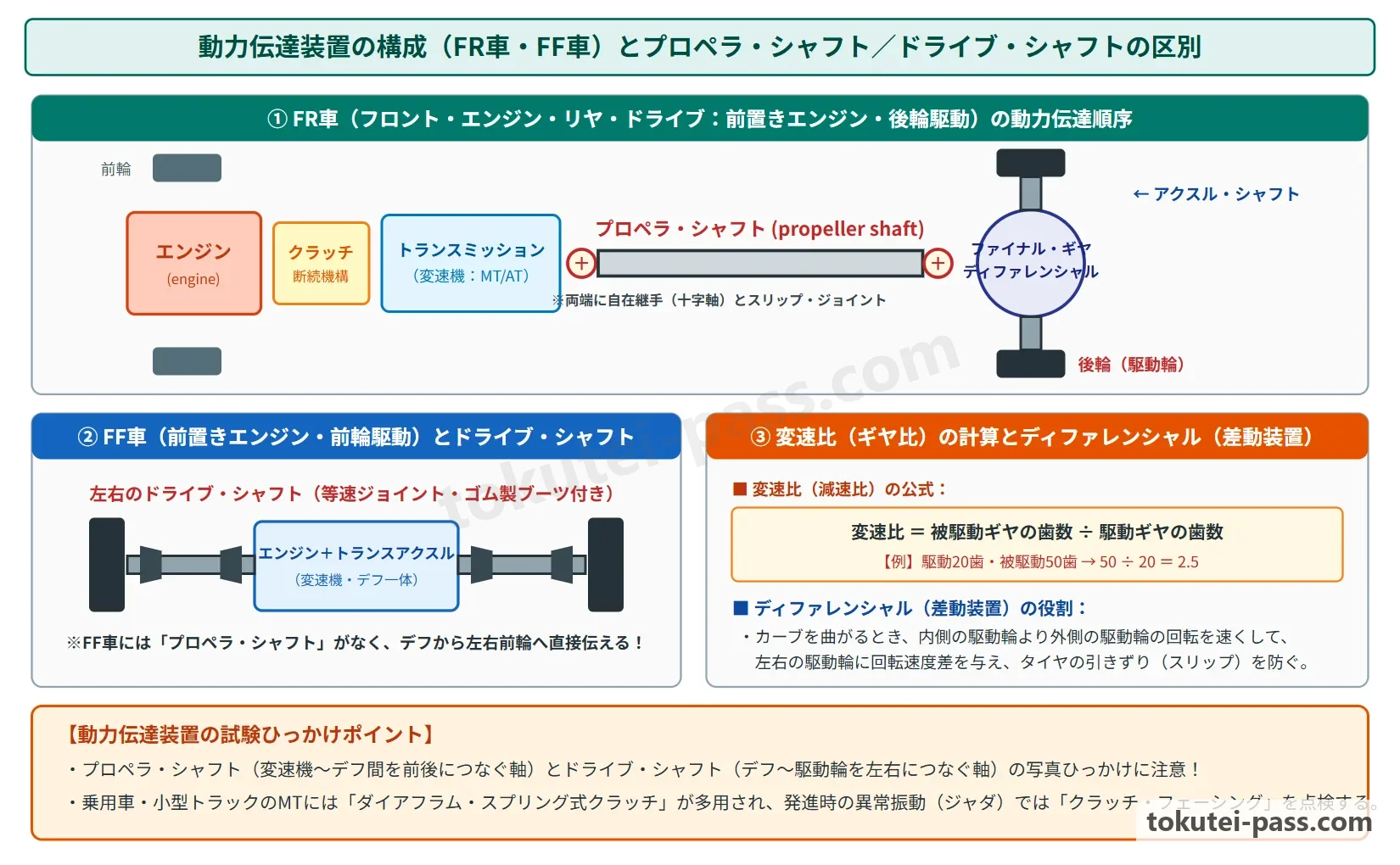
エンジンを前に置いて後輪を駆動するFR車では、「エンジン → クラッチ → トランスミッション → プロペラ・シャフト → ファイナル・ギヤ(ディファレンシャル) → アクスル・シャフト(ドライブ・シャフト) → 後輪」の順に動力が伝わります。
In an FR (front-engine, rear-wheel-drive) vehicle, power flows in the order: Engine → Clutch → Transmission → Propeller shaft → Final gear (Differential) → Axle shafts (Drive shafts) → Rear wheels.
一方、エンジンを前に置いて前輪を駆動するFF車では、トランスミッションとファイナル・ギヤ(ディファレンシャル)を一体化した「トランスアクスル(transaxle)」が用いられます。
In contrast, an FF (front-engine, front-wheel-drive) vehicle uses a transaxle that integrates the transmission and final gear (differential) into a single unit.
トランスアクスルから左右の「ドライブ・シャフト(drive shaft)」で直接前輪を回すため、FF車には「プロペラ・シャフト(propeller shaft)」がありません。
Because left and right drive shafts directly drive the front wheels from the transaxle, an FF vehicle has no propeller shaft.
2つの歯車(ギヤ)が噛み合うときの変速比(ギヤ比)は、「変速比 = 被駆動歯車(回される側)の歯数 ÷ 駆動歯車(回す側)の歯数」で求めます。小さい歯車で大きい歯車を回すと、回転速度は「1 ÷ 変速比」に減速され、トルク(回転力)は「変速比」倍に増大します。
When two gears mesh, the gear ratio is calculated by: Gear ratio = Number of teeth on driven gear ÷ Number of teeth on drive gear. Driving a large gear with a small gear reduces rotational speed to 1 ÷ gear ratio and multiplies torque by the gear ratio.
さらに、トランスミッションの変速比とファイナル・ギヤの減速比を掛け合わせたものを「総減速比(総変速比 = 変速比 × 終減速比)」といいます。発進時や登坂時は1速などの大きな変速比を選んで大きな駆動力を得ます。
Furthermore, the product of the transmission gear ratio and the final gear reduction ratio is called the total reduction ratio (overall gear ratio = transmission gear ratio × final reduction ratio). When starting off or climbing a hill, a large gear ratio such as 1st gear is selected to obtain high driving force.
Key points
- FR車はプロペラ・シャフトで後輪側へ動力を伝えるが、FF車はトランスアクスルからドライブ・シャフトで直接前輪を駆動するためプロペラ・シャフトがない
FR vehicles use a propeller shaft to send power to the rear axle, whereas FF vehicles drive the front wheels directly from the transaxle via drive shafts and have no propeller shaft - 変速比(ギヤ比)= 被駆動歯車の歯数 ÷ 駆動歯車の歯数 であり、減速すると回転速度は下がりトルクは変速比に比例して大きくなる
Gear ratio = Driven gear teeth ÷ Drive gear teeth; speed reduction lowers rotational speed and increases torque in proportion to the gear ratio - 総減速比 = トランスミッションの変速比 × ファイナル・ギヤの減速比 で求める
Total reduction ratio = Transmission gear ratio × Final gear reduction ratio - 【例】駆動ギヤの歯数が 15、被駆動ギヤの歯数が 45 のとき、変速比 = 45 ÷ 15 = 3.0 となり、回転速度は 1/3、トルクは 3倍になる
Example: When the drive gear has 15 teeth and the driven gear has 45 teeth, gear ratio = 45 ÷ 15 = 3.0, rotational speed becomes 1/3, and torque becomes 3 times greater - 【例】トランスミッションの変速比が 2.5、ファイナル・ギヤの減速比が 4.0 のとき、総減速比 = 2.5 × 4.0 = 10.0 となる
Example: When the transmission gear ratio is 2.5 and the final gear reduction ratio is 4.0, the total reduction ratio = 2.5 × 4.0 = 10.0
| Word | Meaning |
|---|---|
| プロペラ・シャフト(propeller shaft) | Propeller shaft |
| ドライブ・シャフト(drive shaft) | Drive shaft |
| トランスアクスル(transaxle) | Transaxle |
| 変速比(ギヤ比) | Gear ratio (transmission ratio) |
クラッチ(clutch)の構造・作用とペダルの遊び
Clutch Structure, Operation, and Pedal Free Play
クラッチ(clutch)はエンジンとトランスミッションの間に設けられ、動力を断続する装置です。発進時に摩擦によって動力を滑らかに伝える働きと、変速時および停止時に動力を確実に遮断する働きを持っています。
The clutch is located between the engine and transmission to connect and disconnect power. It smoothly engages power via friction when starting off and cleanly interrupts power when shifting gears or stopping.
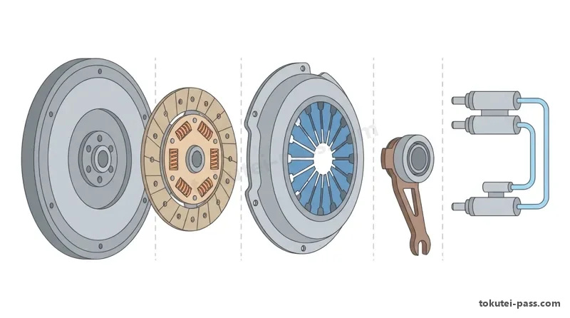
マニュアル車(MT車)では、円板状のばねを用いた「ダイヤフラム・スプリング式乾式単板クラッチ」が広く使われています。クラッチ・ディスクの両面には摩擦材(フェーシング)が張られており、フライホイールとプレッシャ・プレートの間に強く押し付けられることで動力を伝えます。
Manual transmission (MT) vehicles widely use a dry single-plate clutch with a disc-shaped diaphragm spring. Friction facings are riveted to both sides of the clutch disc, which is pressed tightly between the flywheel and pressure plate to transmit power.
クラッチ・ディスクの中央部にはコイルばね(トーション・スプリング)が組み込まれており、クラッチ接続時の回転衝撃やエンジンの回転変動を吸収します。
Coil springs (torsion springs) are built into the hub of the clutch disc to absorb rotational shock during engagement and dampen engine torque fluctuations.
油圧式操作機構では、ペダルを踏むとクラッチ・マスタ・シリンダの油圧がレリーズ・シリンダへ伝わり、レリーズ・フォークとレリーズ・ベアリングを介してダイヤフラム・スプリングの中央を押して動力を切ります。
In a hydraulic clutch release mechanism, pressing the pedal sends hydraulic pressure from the clutch master cylinder to the release cylinder, pushing the center of the diaphragm spring via the release fork and release bearing to disengage the clutch.
クラッチ・ペダルには、指で軽く押して抵抗を感じるまでの「遊び(free play)」が必要です。
The clutch pedal requires a specified amount of free play—the distance the pedal moves when pressed lightly by finger until resistance is felt.
クラッチ・ディスク(フェーシング)が摩耗すると、プレッシャ・プレートがフライホイール側へ寄るため、ペダルの遊びは「減少(小さく)します」。遊びがゼロになるとクラッチが滑り、逆に遊びが過大だとクラッチの切れ不良(ギヤ鳴り)を起こします。
As the clutch disc facing wears down, the pressure plate moves closer to the flywheel, causing clutch pedal free play to decrease (become smaller). If free play reaches zero, the clutch slips; conversely, excessive free play causes poor disengagement (gear grinding during shifts).
Key points
- クラッチ・ディスクのトーション・スプリングは、接続時の衝撃や回転変動を吸収して滑らかに動力を伝える
Torsion springs in the clutch disc absorb engagement shock and rotational fluctuations for smooth power transmission - クラッチ・ディスク(フェーシング)が摩耗すると、クラッチ・ペダルの遊びは減少(小さく)する(増えるのではない点に注意)
As the clutch disc (facing) wears, clutch pedal free play decreases (becomes smaller—note that it does not increase) - クラッチ・ペダルの遊びが過小(ゼロ)になるとクラッチの「滑り」が発生し、遊びが過大になるとクラッチの「切れ不良」が発生する
Insufficient (zero) clutch pedal free play causes clutch slipping, whereas excessive free play causes poor clutch disengagement
| Word | Meaning |
|---|---|
| ダイヤフラム・スプリング(diaphragm spring) | Diaphragm spring |
| クラッチ・ディスク(clutch disc) | Clutch disc |
| トーション・スプリング(torsion spring) | Torsion spring |
| レリーズ・ベアリング(release bearing) | Release bearing |
トランスミッション(MT・AT・CVT)の構造と機能
Transmission Structure and Function (MT, AT, and CVT)
マニュアル・トランスミッション(MT)には、変速時に噛み合うギヤ同士の回転速度を円錐面(コーン部)の摩擦によって一致(同期)させる「シンクロメッシュ機構(同期噛合い機構)」が備わっています。
A manual transmission (MT) is equipped with a synchromesh mechanism that uses friction on the conical surface of a synchronizer ring to match (synchronize) the rotational speeds of meshing gears during shifting.
これにより、ギヤ鳴りを防いで軽い操作力でスムーズに変速できます。また、2つのギヤが同時に噛み合うのを防ぐ「二重噛合い防止機構(インターロック機構)」も設けられています。
This prevents gear clash (grinding) and allows smooth shifting with light effort. An interlock mechanism is also provided to prevent two gears from engaging simultaneously.
オートマチック・トランスミッション(AT)のトルク・コンバータは、ATF(作動油)を介して動力を伝える流体継手の一種です。エンジンで回される「ポンプ・インペラ」、出力軸につながる「タービン・ランナ」、およびその間でワンウェイ・クラッチに支えられた「ステータ(stator)」の3要素で構成されます。
The torque converter of an automatic transmission (AT) is a hydrodynamic coupling that transmits power through ATF (automatic transmission fluid). It consists of three elements: a pump impeller driven by the engine, a turbine runner connected to the output shaft, and a stator supported on a one-way clutch between them.
ステータは、タービン・ランナから戻ってきたATFの流れの向きを変えてポンプ・インペラの回転を助けることで、トルクを増大させる働きをします。また、高速巡航時には流体の滑りによる燃費悪化を防ぐため、入力側と出力側を機械的に直結する「ロックアップ機構」が作動します。
The stator redirects ATF returning from the turbine runner so that it assists pump impeller rotation, thereby multiplying torque. During high-speed cruising, a lock-up mechanism mechanically connects the input and output sides to eliminate fluid slip loss and improve fuel economy.
ATの歯車変速部にはプラネタリ・ギヤ(遊星歯車機構)が使われ、CVT(無段変速機)ではプライマリ・プーリとセカンダリ・プーリの溝幅を油圧で変化させ、スチール・ベルトやチェーンの巻き掛け径を連続的に変えることで段階のない滑らかな変速を行います。
The gear unit of an AT uses planetary gear sets, whereas a CVT (Continuously Variable Transmission) uses hydraulic pressure to vary the groove widths of primary and secondary pulleys, continuously changing the running radius of a steel belt or chain for stepless, smooth shifting.
Key points
- MTのシンクロメッシュ機構は、シンクロナイザ・リングの摩擦によってギヤの回転速度を同期(一致)させ、変速時のギヤ鳴りを防ぐ
The MT synchromesh mechanism uses synchronizer ring friction to synchronize gear speeds and prevent gear noise during shifting - トルク・コンバータはポンプ・インペラ(入力)、タービン・ランナ(出力)、ステータ(ATFの流れを変えてトルク増大)で構成され、ロックアップ機構は流体の滑り損失をなくす
A torque converter consists of a pump impeller (input), turbine runner (output), and stator (torque multiplication), while the lock-up clutch eliminates fluid slip loss - CVT(無段変速機)は2つのプーリの溝幅を変えてスチール・ベルトやチェーンの巻き掛け半径を無段階に変化させる
A CVT varies the groove width of two pulleys to change the steel belt or chain wrap radius steplessly
| Word | Meaning |
|---|---|
| シンクロメッシュ機構 | Synchromesh mechanism |
| トルク・コンバータ(torque converter) | Torque converter |
| プラネタリ・ギヤ(遊星歯車) | Planetary gear |
| ロックアップ機構 | Lock-up mechanism |
プロペラ・シャフトとドライブ・シャフト(ユニバーサル・ジョイント)
Propeller Shafts and Drive Shafts (Universal Joints)
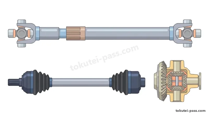
FR車や4WD車のプロペラ・シャフト(propeller shaft)は、車体に固定されたトランスミッションと、路面の凹凸で絶えず上下動するディファレンシャル(ファイナル・ギヤ)を結んでいます。
In FR and 4WD vehicles, the propeller shaft connects the transmission (fixed to the body) with the differential/final gear (which moves up and down continuously with road bumps).
そのため、接続角度の変化に対応する「ユニバーサル・ジョイント(自在継手)」と、軸方向の長さ変化を吸収する「スリーブ・ヨーク(スプライン部)」が設けられています。
Therefore, it is equipped with universal joints to accommodate changes in joint angle and a sleeve yoke (splined slip joint) to absorb axial length changes.
プロペラ・シャフトに用いられるフック・ジョイント(十字軸式ジョイント)は、1個だけでは入力軸と出力軸に角度がついたときに1回転ごとの速度変動(不等速性)が生じます。そこで、シャフトの両端に2個のフック・ジョイントを配置して速度変動を打ち消し、等速で動力を伝える構造になっています。
A single Hooke joint (cross-type universal joint) used on a propeller shaft produces rotational speed fluctuations twice per revolution when operating at an angle. Therefore, two Hooke joints are arranged at both ends of the shaft to cancel out speed fluctuations and transmit rotation at constant velocity.
一方、FF車の前輪や独立支持式の駆動輪を回すドライブ・シャフト(drive shaft)には、ハンドルを切ったときの大きな交差角でも回転変動を起こさず滑らかに動力を伝える「等速ジョイント(CVJ:コンスタント・ベロシティ・ジョイント)」が使われます。
In contrast, drive shafts that drive the front wheels of FF vehicles or independent-suspension drive wheels use constant velocity joints (CVJs) that transmit power smoothly without rotational fluctuations even at large steering angles.
ドライブ・シャフトのホイール(タイヤ)側には大きな操舵角に対応できるバーフィールド型(ツェッパ型)等速ジョイントが使われ、ディファレンシャル側には角度変化だけでなく軸方向の伸縮(スライド)もできるトリポード型やダブル・オフセット型等速ジョイントが使われます。
Barfield (Rzeppa) CV joints capable of large steering angles are used on the wheel (outboard) side of the drive shaft, while tripod or double-offset CV joints capable of both angular change and axial sliding (plunge) are used on the differential (inboard) side.
ジョイント部はゴム製のドライブ・シャフト・ブーツで覆われ、グリースが封入されています。
Each joint is sealed by a rubber drive shaft boot filled with special grease.
Key points
- プロペラ・シャフトのスリーブ・ヨーク(スプライン)は、サスペンションの上下動に伴う軸方向の長さ変化(伸縮)を吸収する
The sleeve yoke (spline) of a propeller shaft absorbs axial length changes caused by up-and-down suspension movement - フック・ジョイント(十字軸式)は交差角があると回転速度変動が生じるため、2個以上を組み合わせて不等速性を打ち消す
Because a Hooke joint causes speed fluctuations at an angle, two or more joints are combined to cancel out non-constant velocity - FF車のドライブ・シャフトには回転変動の起きない等速ジョイント(ホイール側:バーフィールド型、デフ側:伸縮可能なトリポード型など)が用いられる
FF drive shafts use constant velocity joints (CVJs: Barfield type on the wheel side and sliding tripod/double-offset type on the differential side)
| Word | Meaning |
|---|---|
| ユニバーサル・ジョイント(自在継手) | Universal joint |
| スリーブ・ヨーク(sleeve yoke) | Sleeve yoke |
| フック・ジョイント(Hooke joint) | Hooke joint (cross joint) |
| 等速ジョイント(CVJ) | Constant velocity joint (CVJ) |
ファイナル・ギヤ(終減速機)とディファレンシャル(差動装置)
Final Gear (Final Reduction) and Differential
ファイナル・ギヤ(final gear:終減速機)は、ドライブ・ピニオンとリング・ギヤの噛み合いによって回転速度を最終的に減速し、駆動トルクを大きくする装置です。FR車ではハイポイド・ギヤやスパイラル・ベベル・ギヤを用いて、動力の伝達方向を直角(90°)に変えて左右の車軸へ分けます。
The final gear performs the final speed reduction and torque multiplication through the meshing of the drive pinion and ring gear. In FR vehicles, hypoid gears or spiral bevel gears are used to turn the direction of power transmission by 90° toward the left and right axle shafts.
ハイポイド・ギヤは、リング・ギヤの中心線よりもドライブ・ピニオンの軸線を下側にオフセット(偏心)させたかさ歯車です。これによりプロペラ・シャフトの位置を低くして室内の床を低くでき、噛み合い率が大きく静かですが、歯面のすべり速度が高いため極圧性の高いハイポイド・ギヤ・オイルが必要です。
A hypoid gear is a bevel gear set in which the drive pinion axis is offset below the center line of the ring gear. This lowers the propeller shaft and cabin floor and provides quiet operation with a high contact ratio, but high tooth sliding speed requires extreme-pressure hypoid gear oil.
自動車がカーブを曲がる(旋回する)とき、外側のタイヤは内側のタイヤよりも長い距離を走るため、左右の駆動輪に回転速度差が生じます。この回転差を自動的に吸収してタイヤのスリップを防ぎ、スムーズに旋回させる装置が「ディファレンシャル(differential:差動装置)」です。
When a vehicle turns a corner, the outer wheel travels a longer distance than the inner wheel, creating a rotational speed difference between the left and right drive wheels. The differential automatically absorbs this speed difference to prevent tire scrubbing and allow smooth cornering.
ディファレンシャルは、リング・ギヤと一体で回るデフ・ケース、その内部のピニオン・シャフトに支えられたデフ・ピニオン、および左右の車軸につながるサイド・ギヤで構成されます。直進時はデフ・ピニオンは自転せずデフ・ケースと一体で公転し、左右のサイド・ギヤは同じ速度で回転します。
The differential consists of a differential case rotating integrally with the ring gear, differential pinions supported on a pinion shaft inside the case, and left and right side gears connected to the axles. When driving straight ahead, the differential pinions do not spin on their own axis but revolve together with the case, rotating both side gears at the same speed.
Key points
- FR車のファイナル・ギヤにはハイポイド・ギヤなどが使われ、動力を最終減速するとともに回転方向を直角(90°)に変換する
FR final gears use hypoid gears to perform final speed reduction and change the direction of rotation by 90° - ディファレンシャル(差動装置)は、旋回時などに生じる左右駆動輪の回転速度差(外輪>内輪)を自動的に吸収する
The differential automatically absorbs the rotational speed difference between left and right drive wheels (outer wheel > inner wheel) during cornering - 直進走行時は左右の駆動輪の抵抗が等しいため、デフ・ピニオンは自転せずにデフ・ケースと一体となって回り、左右のサイド・ギヤは同じ速度で回転する
When driving straight, road resistance on both wheels is equal, so the differential pinions do not spin on their own shaft and both side gears rotate at the same speed
| Word | Meaning |
|---|---|
| ファイナル・ギヤ(終減速機) | Final gear (final reduction unit) |
| ハイポイド・ギヤ(hypoid gear) | Hypoid gear |
| ディファレンシャル(差動装置) | Differential |
| デフ・ピニオンとサイド・ギヤ | Differential pinion and side gear |
ディファレンシャルの回転特性とLSD(差動制限装置)
Differential Rotational Characteristics and LSD (Limited Slip Differential)
ディファレンシャルには、「左サイド・ギヤの回転数 + 右サイド・ギヤの回転数 = リング・ギヤ(デフ・ケース)の回転数 × 2」という重要な関係があります。つまり、片方のタイヤの回転が減少した分だけ、もう片方のタイヤの回転が同じ量だけ増加します。
The differential obeys the key relationship: Left side gear speed + Right side gear speed = Ring gear (differential case) speed × 2. That is, whatever speed one wheel loses, the opposite wheel gains by the exact same amount.
たとえばリング・ギヤが 100 rpm で回っているとき、直進中は左輪 100 rpm・右輪 100 rpm です。
For example, when the ring gear rotates at 100 rpm while driving straight ahead, both the left and right wheels rotate at 100 rpm.
もし旋回中に内輪が 80 rpm に下がると、外輪は 200 - 80 = 120 rpm で回ります。また、ジャッキアップして片輪を固定(0 rpm)すると、反対側の車輪はリング・ギヤの2倍の 200 rpm で回転します。
If the inner wheel slows to 80 rpm during a turn, the outer wheel rotates at 200 - 80 = 120 rpm. Furthermore, if the vehicle is jacked up and one wheel is held stationary (0 rpm), the opposite wheel rotates at twice the ring gear speed, or 200 rpm.
この特性のため、標準のディファレンシャルでは、片方の駆動輪がぬかるみや氷の上に乗ってスリップ(空転)すると、空転側ばかりが高速で回り、接地している反対側のタイヤにも動力が伝わらなくなって脱出できなくなります。
Because of this property, with a standard open differential, if one drive wheel slips on mud or ice, only the slipping wheel spins rapidly while no driving force is transmitted to the opposite wheel on firm ground, making it impossible to get unstuck.
これを防ぐため、左右輪に大きな回転差が生じたときに差動作用を制限し、空転していない側のタイヤへも駆動力を配分する「LSD(リミテッド・スリップ・ディファレンシャル:差動制限装置)」がスポーツ車や悪路走行車などに用いられます。
To prevent this, sports cars and off-road vehicles use an LSD (Limited Slip Differential) that restricts differential action when a large speed difference occurs, distributing driving torque to the non-slipping wheel as well.
Key points
- 左右のサイド・ギヤ(駆動輪)の回転数の平均は、常にリング・ギヤ(デフ・ケース)の回転数と等しい(左+右 = リング・ギヤ×2)
The average speed of the left and right side gears (drive wheels) always equals the ring gear speed (Left + Right = Ring gear × 2) - 片輪がぬかるみ等で空転すると、他方のタイヤにも駆動力が伝わらなくなるため、差動を制限するLSD(差動制限装置)が用いられる
If one wheel spins on mud or ice, the other wheel loses drive torque too; an LSD (Limited Slip Differential) restricts differential action to maintain traction - 【例】リング・ギヤが 150 rpm で回転しているとき、片方の車輪が止まって 0 rpm になると、もう片方の車輪は2倍の 300 rpm で回転する
Example: When the ring gear rotates at 150 rpm and one wheel is stopped at 0 rpm, the opposite wheel rotates at twice that speed: 300 rpm - 【例】リング・ギヤが 100 rpm で回転し、旋回時に内側の車輪が 70 rpm になったとき、外側の車輪は (100 × 2) - 70 = 130 rpm となる
Example: When the ring gear rotates at 100 rpm and the inner wheel slows to 70 rpm in a turn, the outer wheel rotates at (100 × 2) - 70 = 130 rpm
| Word | Meaning |
|---|---|
| 差動作用 | Differential action |
| 空転(スリップ) | Wheel spin (slip) |
| LSD(差動制限装置) | LSD (Limited Slip Differential) |
動力伝達装置の点検と整備上の注意点
Drivetrain Inspection and Maintenance Precautions
クラッチの日常・定期点検では、クラッチ・リザーバ・タンクの液量が上限(MAX)と下限(MIN)の間にあるかを確認し、クラッチ・ペダルの「遊び」と、ペダルを一杯に踏み込んだときの「床板とのすき間」、およびエンジン始動状態で異音なくスムーズに変速できるかを点検します。
During routine and periodic clutch inspections, check that the fluid level in the clutch reservoir tank is between MAX and MIN, measure clutch pedal free play and pedal-to-floor clearance when fully depressed, and verify smooth gear shifting without abnormal noise with the engine running.
トランスミッション・オイル(MT車)やディファレンシャル・ギヤ・オイルの点検では、車両を水平にしてフィラ・プラグ(注入口)を外し、油面がプラグ穴の下縁付近まであるか、およびドレン・プラグ周りやオイル・シールからの油漏れがないかを確認します。
To inspect manual transmission (MT) oil or differential gear oil, park the vehicle level, remove the filler plug, and check that the oil level reaches near the bottom edge of the plug hole and that there are no leaks around the drain plug or oil seals.
AT車のATF(オートマチック・トランスミッション・フルード)は温度で体積が変化します。そのためエンジンを暖機してアイドリング状態にし、セレクト・レバーを全レンジへ一巡させてから「P」(または「N」)に戻し、レベル・ゲージの「HOT」範囲内にあるかを点検します。
Because automatic transmission fluid (ATF) expands with temperature, warm up the engine to normal operating temperature, let it idle, shift the selector lever slowly through all ranges and back to P (or N), and check that the fluid level is within the HOT range on the dipstick.
また、FF車や4WD車のドライブ・シャフトでは、等速ジョイントを保護しているゴム製の「ドライブ・シャフト・ブーツ」に破れ(亀裂)やグリース漏れがないかを必ず目視点検します。ブーツが破れたまま走行すると、内部に水や砂が入ってジョイントが摩耗し、旋回時に「カラカラ」「ゴキゴキ」という異音が発生します。
On FF and 4WD vehicles, always visually inspect the rubber drive shaft boots protecting the CV joints for tears, cracks, or grease leakage. Driving with a torn boot lets water and sand enter the joint, causing rapid wear and clicking or popping noises when turning.
Key points
- クラッチ点検では、ペダルの遊び、踏み込んだときの床板とのすき間、およびリザーバ・タンクの液量を確認する
Clutch inspection includes checking pedal free play, floor clearance when fully depressed, and reservoir fluid level - AT車のATF量点検は、暖機後エンジンをアイドリング状態にしたままセレクト・レバーを全レンジに一巡させ、P(またはN)レンジで測定する
Check AT fluid (ATF) level with the engine warmed up and idling, after shifting through all ranges and returning the lever to P (or N) - ドライブ・シャフト・ブーツが破れてグリースが漏れると、等速ジョイントに水や砂が侵入して旋回時に異音や破損を起こす
A torn drive shaft boot leaks grease and allows water and dirt into the CV joint, causing abnormal noise and failure during cornering
| Word | Meaning |
|---|---|
| ATF(オートマチック・トランスミッション・フルード) | ATF (Automatic Transmission Fluid) |
| フィラ・プラグとドレン・プラグ | Filler plug and drain plug |
| ドライブ・シャフト・ブーツ | Drive shaft boot |
試験によく出るポイントと覚え方
Frequently Tested Points and Memory Tips
クラッチで最も狙われる引っ掛けは「クラッチ・ディスクが摩耗するとペダルの遊びはどうなるか」です。
The most common trap question on clutches is: What happens to clutch pedal free play when the clutch disc wears?
ブレーキ・パッドやシューの摩耗とは逆で、クラッチ・ディスクが摩耗するとプレッシャ・プレートがフライホイール側に寄るため、クラッチ・ペダルの遊びは「減少(小さく)する」が正解です。遊びがなくなると「滑り」、大きすぎると「切れ不良」になります。
Unlike brake pads, as the clutch disc wears, the pressure plate moves closer to the flywheel, so clutch pedal free play decreases (becomes smaller). Zero free play causes clutch slipping, while excessive free play causes poor disengagement.
トランスミッションでは、「MTのシンクロメッシュ機構=摩擦でギヤの回転を同期させてギヤ鳴りを防ぐ」「ATのトルク・コンバータ=ポンプ・インペラ(入力)、タービン・ランナ(出力)、ステータ(トルク増大)の3要素」「ロックアップ機構=流体の滑りをなくして燃費向上」をセットで覚えましょう。
For transmissions, memorize as a set: MT synchromesh = synchronizes gear speeds by friction to prevent gear clash; AT torque converter = Pump impeller (input), Turbine runner (output), and Stator (torque multiplication); Lock-up mechanism = direct mechanical coupling to eliminate fluid slip and improve fuel economy.
シャフトとジョイントの区別では、「FR車にはプロペラ・シャフト(フック・ジョイント+伸縮用スリーブ・ヨーク)があるが、FF車にはプロペラ・シャフトがなくドライブ・シャフト(等速ジョイント)で前輪を回す」という対比が頻出です。
For shafts and joints, contrast FR vs. FF: FR vehicles have a propeller shaft (Hooke joints + sliding sleeve yoke), whereas FF vehicles have no propeller shaft and drive the front wheels directly with drive shafts (CV joints).
ディファレンシャルと変速比では、「変速比=回される歯数(被駆動)÷回す歯数(駆動)」「直進時はデフ・ピニオンは自転しない」「片輪を止めるともう片輪は2倍の速度で回る」の3つのルールを確実に押さえておきましょう。
For differentials and gear ratios, lock in three rules: Gear ratio = Driven teeth ÷ Drive teeth; Differential pinions do not spin on their own axis when driving straight; Stopping one wheel makes the opposite wheel spin at twice the ring gear speed.
Key points
- クラッチ・ディスクが摩耗するとペダルの遊びは「減少」する / 遊び過小=滑り、遊び過大=切れ不良
Clutch disc wear causes pedal free play to decrease / Too little free play = slipping; too much free play = poor disengagement - シンクロメッシュ機構=回転同期 / トルク・コンバータのステータ=トルク増大 / ロックアップ機構=直結して滑り損失を防ぐ
Synchromesh = speed synchronization / Torque converter stator = torque multiplication / Lock-up clutch = direct connection to prevent slip loss - FF車にはプロペラ・シャフトがなく、等速ジョイント(CVJ)を備えたドライブ・シャフトで前輪を駆動する
FF vehicles have no propeller shaft and drive the front wheels using drive shafts equipped with constant velocity joints (CVJs) - ディファレンシャルは旋回時の左右輪の回転差を吸収し、直進時はデフ・ピニオンは自転せずデフ・ケースと一体で公転する
The differential absorbs left-right wheel speed differences in turns; when driving straight, diff pinions revolve with the case without spinning on their own axis - 変速比=被駆動歯数÷駆動歯数 / 総減速比=トランスミッション変速比×ファイナル・ギヤ減速比
Gear ratio = Driven teeth ÷ Drive teeth / Total reduction ratio = Transmission gear ratio × Final gear reduction ratio
| Word | Meaning |
|---|---|
| ペダルの遊び(free play) | Pedal free play |
| 切れ不良 | Poor disengagement |
| 自転と公転 | Spinning on own axis (rotation) and revolving (revolution) |
Drivetrain
Practice this chapter in the appOfficial references
- 一般社団法人 日本自動車整備振興会連合会(JASPA)「自動車整備分野特定技能評価試験 学習用テキスト(三級自動車整備士講習用テキスト準拠)」 — https://www.jaspa.or.jp/
- 国土交通省 物流・自動車局「自動車整備分野特定技能1号評価試験 試験実施要領」 — https://www.mlit.go.jp/jidosha/jidosha_fr10_000041.html