
Electrical Equipment (Battery, Starting, Charging, Ignition, and Lighting)
電装品(バッテリ・始動・充電・点火・灯火)
Automobile Maintenance · 自動車整備分野 · Written by Tokutei Pass based on the official study texts; not copied verbatim.
バッテリ(鉛蓄電池)の構造・比重・取扱い
Lead-Acid Battery Structure, Specific Gravity, and Handling
自動車のバッテリには鉛蓄電池が使われています。正極板(二酸化鉛)と負極板(海綿状鉛)がセパレータ(隔離板)を介して電解液(希硫酸)に浸されており、1セルあたりの起電力は約2 Vです。乗用車の12 Vバッテリは6個のセルを直列に接続しています。
Automotive batteries use lead-acid storage batteries. Positive plates (lead dioxide, PbO2) and negative plates (spongy lead, Pb) are separated by separators and immersed in electrolyte (dilute sulfuric acid, H2SO4), producing an electromotive force of about 2 V per cell. A 12 V passenger car battery connects 6 cells in series.
バッテリが放電すると極板が硫酸鉛に変わり、電解液の硫酸分が減って水に近づくため比重が下がります。完全充電時の電解液比重は、標準温度20℃において 1.26〜1.28 です。液温が1℃変化するごとに比重は 0.0007 変化するため、換算式「S20=St+0.0007×(t-20)」で補正します。
As the battery discharges, both plates turn into lead sulfate (PbSO4) and the sulfuric acid in the electrolyte decreases, making the liquid closer to water and lowering its specific gravity. The specific gravity of a fully charged battery at the standard temperature of 20°C is 1.26 to 1.28. Because specific gravity changes by 0.0007 per 1°C, it is converted to 20°C using the formula S20 = St + 0.0007 × (t - 20).
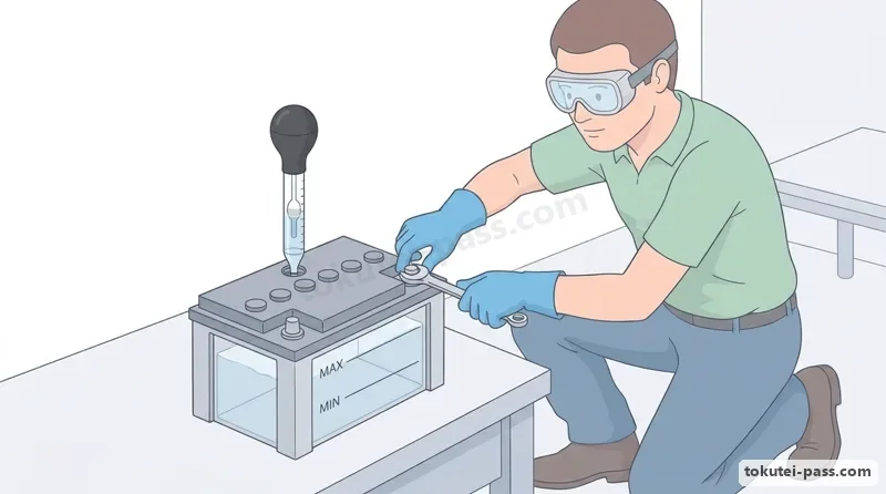
自然蒸発などで電解液が不足したときは、硫酸分は蒸発しないため、必ず精製水(蒸留水)を上限線(UPPER LEVEL)まで補充します。また、充電中は引火・爆発性のある水素ガスが発生するため、換気を良くして火気厳禁とします。
When the electrolyte level drops due to natural evaporation, sulfuric acid does not evaporate, so you must refill with purified water (distilled water) up to the UPPER LEVEL line. Also, because flammable and explosive hydrogen gas is generated during charging, ensure good ventilation and strictly prohibit open flames.
バッテリ端子からケーブルを取り外すときは、工具が車体(ボデー)に触れてショートするのを防ぐため、必ずマイナス(-)端子(アース側)から先に外します。逆に取り付けるときは、プラス(+)端子から先に接続し、最後にマイナス(-)端子を接続します。
When disconnecting cables from battery terminals, always disconnect the negative (-) terminal (ground side) first so that a wrench touching the metal vehicle body will not cause a short circuit. Conversely, when connecting cables, connect the positive (+) terminal first and the negative (-) terminal last.
Key points
- 12 Vバッテリは1セル約2 Vのセルを6個直列にしたもので、20℃における完全充電時の電解液比重は 1.26〜1.28 である
A 12 V battery consists of six 2 V cells in series, and its fully charged electrolyte specific gravity at 20°C is 1.26 to 1.28 - 電解液が自然減少したときは精製水(蒸留水)を補充し、充電中は爆発性の水素ガスが出るため火気厳禁とする
Refill natural electrolyte loss with purified (distilled) water, and keep flames away during charging because explosive hydrogen gas is released - ケーブルを外すときはショート防止のためマイナス(-)端子から先に外し、取り付けるときはプラス(+)端子から先に取り付ける
To prevent short circuits, disconnect the negative (-) terminal first when removing cables, and connect the positive (+) terminal first when installing - 【例】液温30℃での測定比重 St が 1.263 のとき、20℃換算比重 S20 = 1.263 + 0.0007 × (30 - 20) = 1.263 + 0.007 = 1.270 となる
Example: When measured specific gravity St is 1.263 at an electrolyte temperature of 30°C, the 20°C converted specific gravity is S20 = 1.263 + 0.0007 × (30 - 20) = 1.263 + 0.007 = 1.270 - 【例】5時間率容量が 40 Ah(アンペア・アワー)のバッテリは、40 ÷ 5 = 8 A の一定電流で5時間放電できる容量を表す
Example: A battery rated at 40 Ah (ampere-hours) at a 5-hour rate can discharge a constant current of 40 ÷ 5 = 8 A for 5 hours
| Word | Meaning |
|---|---|
| 電解液(希硫酸) | Electrolyte (dilute sulfuric acid) |
| 精製水(蒸留水) | Purified water (distilled water) |
| 比重 | Specific gravity |
| 水素ガス | Hydrogen gas |
始動装置(スタータ)と充電装置(オルタネータ)
Starting System (Starter) and Charging System (Alternator)
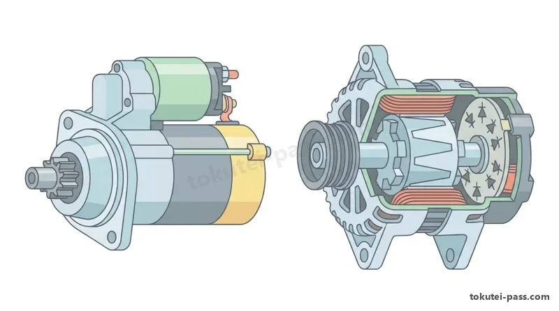
始動装置(スタータ:starter)は、バッテリの電力で直流モータを回し、ピニオン・ギヤをフライホイールのリング・ギヤに噛み合わせてエンジンを始動させます。マグネット・スイッチは、ピニオンを押し出す働きと、モータに流れる大電流のメイン接点を開閉する2つの働きを持っています。
The starting system (starter) uses battery power to spin a DC motor and mesh its pinion gear with the flywheel ring gear to crank the engine. The magnetic switch performs two functions: pushing the pinion gear out to mesh and closing the main contacts to supply heavy current to the motor.
スタータにはオーバランニング・クラッチ(ワンウェイ・クラッチ:一方向クラッチ)が組み込まれています。これはエンジンが始動した直後に、高速回転するリング・ギヤによってスタータのアーマチュア(電機子)が逆に回されて過回転し、破損するのを防ぐためです。
An overrunning clutch (one-way clutch) is built into the starter. Immediately after the engine starts, this clutch prevents the starter armature from being driven backward at excessive speed by the rapidly spinning flywheel ring gear, preventing armature damage.
充電装置のオルタネータ(alternator:交流発電機)は、エンジンのクランク・プーリからベルトで駆動されます。内部で磁界を作って回転するロータ(界磁コイル)と、周囲に固定されて三相交流を発生するステータ(ステータ・コイル)から構成されています。
The alternator (AC generator) of the charging system is driven by a belt from the engine crankshaft pulley. It consists of a spinning rotor (field coil) that creates a magnetic field and a stationary stator (stator coil) around it that generates three-phase alternating current (AC).
ステータ・コイルで発生した三相交流は、内蔵されたレクチファイア(rectifier:整流器・ダイオード)によって直流に変換(整流)されます。また、エンジン回転速度が変化しても発電電圧が規定値(12 V車で約14.0〜14.5 V)を一定に保つよう、ICレギュレータがロータに流す界磁電流を制御しています。
The three-phase AC generated in the stator coil is converted (rectified) into direct current (DC) by a built-in rectifier (diodes). Furthermore, an IC regulator controls the field current flowing to the rotor to keep the generated voltage within a constant specified range (about 14.0 to 14.5 V on 12 V vehicles) even when engine speed changes.
Key points
- スタータのオーバランニング・クラッチは、エンジン始動後にリング・ギヤからアーマチュアが逆駆動されて過回転・破損するのを防ぐ
The starter overrunning clutch prevents the armature from being back-driven and over-revved by the ring gear after the engine starts - オルタネータはロータで磁界を作り、ステータ・コイルで三相交流を発生させ、レクチファイア(ダイオード)で直流に整流する
The alternator creates a magnetic field with the rotor, generates three-phase AC in the stator coil, and rectifies it to DC using the rectifier (diodes) - ICレギュレータはロータの界磁電流を加減し、オルタネータの発生電圧を規定値(約14〜14.5 V)に一定制御する
The IC regulator adjusts rotor field current to maintain alternator output voltage at a constant specified level (about 14 to 14.5 V)
| Word | Meaning |
|---|---|
| スタータ(starter) | Starter |
| オーバランニング・クラッチ(overrunning clutch) | Overrunning clutch (one-way clutch) |
| オルタネータ(alternator) | Alternator |
| レクチファイア(rectifier) | Rectifier (diode) |
| ICレギュレータ(IC regulator) | IC regulator |
点火装置(イグニッション・コイルとスパーク・プラグ)
Ignition System (Ignition Coil and Spark Plug)
ガソリン・エンジンの点火装置は、バッテリの12 Vの低電圧をイグニッション・コイル(ignition coil)で約1万〜3万 Vの高電圧に昇圧し、スパーク・プラグ(spark plug)の電極間に電気火花を飛ばして圧縮された混合気に点火します。
The ignition system of a gasoline engine steps up the low 12 V battery voltage to a high voltage of about 10,000 to 30,000 V using an ignition coil, then discharges an electric spark across the electrodes of the spark plug to ignite the compressed air-fuel mixture.
イグニッション・コイルの内部には、鉄心の周りに巻き数の少ない一次コイルと、その何十倍〜百倍もの巻き数を持つ二次コイルが巻かれています。イグナイタによって一次コイルの電流を急激に遮断した瞬間、自己誘導作用と相互誘導作用によって二次コイルに超高電圧が発生します。
Inside the ignition coil, a primary coil with relatively few turns and a secondary coil with tens to hundreds of times more turns are wound around an iron core. At the instant the igniter abruptly cuts off current in the primary coil, self-induction and mutual induction generate ultra-high voltage in the secondary coil.
スパーク・プラグの中心電極と接地電極のすき間(プラグ・ギャップ)は一般に 0.8〜1.1 mm 程度です。また、プラグが燃焼室から受けた熱をシリンダ・ヘッドへ逃がす度合いを「熱価(ねっか)」といい、熱を逃がしやすいものを高熱価(冷え型)、熱がこもりやすいものを低熱価(焼け型)と呼びます。
The gap between the center electrode and ground electrode of a spark plug (plug gap) is typically about 0.8 to 1.1 mm. The degree to which a spark plug transfers heat from the combustion chamber to the cylinder head is called its heat range: a plug that dissipates heat easily is a cold type (high heat range), and one that retains heat is a hot type (low heat range).
プラグの先端温度が低すぎるとカーボンが付着してくすぶり(ミスファイア)を起こし、高すぎると電極が過熱してプレイグニッション(早期着火)の原因になります。また、エンジン回転速度が高くなるほど、上死点直後で最大燃焼圧力を得るために点火時期を早める(進角させる)制御が行われます。
If the plug tip temperature is too low, carbon builds up and causes fouling (misfire); if it is too high, the electrode overheats and causes pre-ignition. Also, as engine speed increases, ignition timing is advanced so that peak combustion pressure is reached just after Top Dead Center.
Key points
- イグニッション・コイルは一次コイルの電流を遮断したときに生じる誘導作用により、二次コイルに約1万〜3万 Vの高電圧を発生させる
The ignition coil uses electromagnetic induction when primary coil current is interrupted to generate about 10,000 to 30,000 V in the secondary coil - スパーク・プラグの熱価は放熱のしやすさを表し、放熱しやすいものを冷え型(高熱価)、熱が逃げにくいものを焼け型(低熱価)という
Spark plug heat range indicates heat dissipation capacity: a fast-cooling plug is a cold type (high heat range) and a heat-retaining plug is a hot type (low heat range) - エンジンの回転速度が上がるほど燃焼に要するクランク回転角が増えるため、点火時期を早める(進角させる)必要がある
As engine speed increases, ignition timing must be advanced to allow sufficient crank angle for combustion
| Word | Meaning |
|---|---|
| イグニッション・コイル(ignition coil) | Ignition coil |
| スパーク・プラグ(spark plug) | Spark plug |
| 熱価(冷え型・焼け型) | Heat range (cold type and hot type) |
| 点火時期(進角・遅角) | Ignition timing (advance and retard) |
電気の基礎(オームの法則・消費電力・合成抵抗)
Electrical Fundamentals (Ohm's Law, Electric Power, and Combined Resistance)
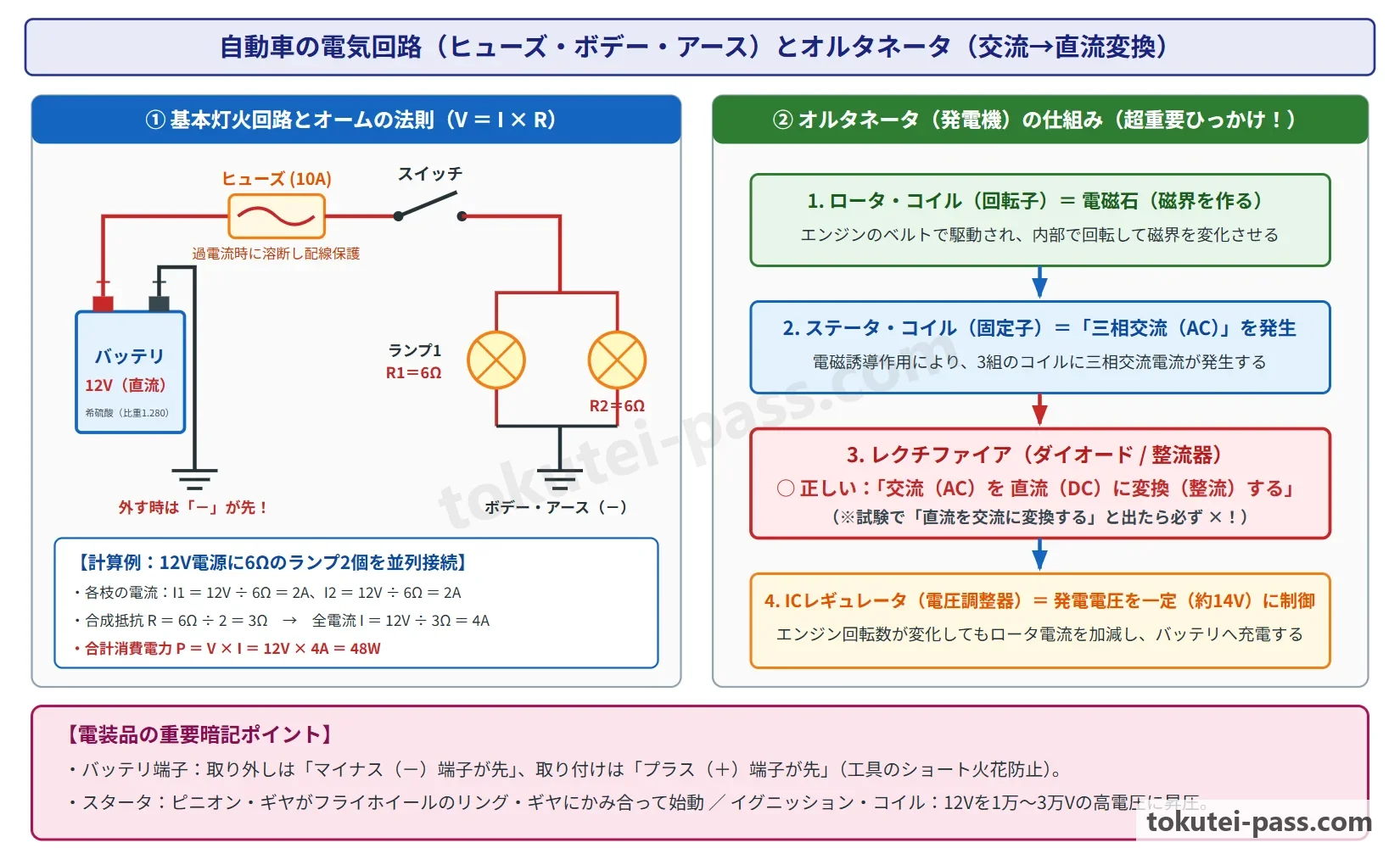
電気回路における電圧 V(ボルト)、電流 I(アンペア)、抵抗 R(オーム:Ω)の間には「V = I × R(電圧=電流×抵抗)」というオームの法則が成り立ちます。変形すると「電流 I = V ÷ R」「抵抗 R = V ÷ I」となり、電装品の点検やヒューズ選定の基礎となります。
In an electrical circuit, voltage V (volts), current I (amperes), and resistance R (ohms, Ω) obey Ohm's law: V = I × R (Voltage = Current × Resistance). Rearranging gives I = V ÷ R and R = V ÷ I, which form the basis for electrical troubleshooting and fuse selection.
また、電球やモータが1秒間に消費する電力 P(ワット:W)は「P = V × I(電力=電圧×電流)」で求められます。たとえば12 Vの電源に60 Wのヘッドランプをつないだ場合、流れる電流 I は 60 ÷ 12 = 5 A です。
The electric power P (watts, W) consumed by a bulb or motor per second is calculated by P = V × I (Power = Voltage × Current). For example, when a 60 W headlamp is connected to a 12 V power supply, the current flowing through it is I = 60 ÷ 12 = 5 A.
複数の抵抗を1本の道筋に並べる「直列接続」では、各抵抗に流れる電流はすべて等しく、合成抵抗 R は各抵抗の和(R = R1 + R2)になります。そのため、直列に抵抗をつなぐほど全体の抵抗は大きくなり、電流は減ります。
In a series connection where multiple resistors are connected along a single path, the current through each resistor is equal and the combined resistance R is the sum of the individual resistances (R = R1 + R2). Adding resistors in series increases total resistance and decreases current.
一方、枝分かれしてつなぐ「並列接続」では、各抵抗にかかる電圧がすべて等しくなり、2つの抵抗の合成抵抗は「R = (R1 × R2) ÷ (R1 + R2)」で求めます。自動車のヘッドランプやテール・ランプなどの各負荷は、片方が切れても他方が消えないようバッテリに対して並列に接続されています。
In a parallel connection where branches split, the voltage across each branch is equal, and the combined resistance of two parallel resistors is R = (R1 × R2) ÷ (R1 + R2). Automotive headlamps, tail lamps, and other loads are connected in parallel across the battery so that if one bulb burns out, the others stay lit.
Key points
- オームの法則は「電圧 V = 電流 I × 抵抗 R」であり、消費電力は「電力 P(W) = 電圧 V(V) × 電流 I(A)」で求める
Ohm's law is V = I × R, and power consumption is P(W) = V(V) × I(A) - 直列接続の合成抵抗は「R = R1 + R2」、並列接続の合成抵抗は「R = (R1 × R2) ÷ (R1 + R2)」となり、自動車の灯火類は並列に接続される
Series combined resistance is R = R1 + R2, while parallel combined resistance is R = (R1 × R2) ÷ (R1 + R2); automotive lamps are wired in parallel - 【例】12 Vのバッテリに 4 Ωのランプと 2 Ωのランプを直列につないだ場合、合成抵抗 R = 4 + 2 = 6 Ω、回路電流 I = 12 ÷ 6 = 2 A となる
Example: When a 4 Ω lamp and a 2 Ω lamp are connected in series to a 12 V battery, combined resistance R = 4 + 2 = 6 Ω and circuit current I = 12 ÷ 6 = 2 A - 【例】12 Vのバッテリに 6 Ωと 3 Ωの抵抗を並列につないだ場合、合成抵抗 R = (6 × 3) ÷ (6 + 3) = 18 ÷ 9 = 2 Ω、全電流 I = 12 ÷ 2 = 6 A となる
Example: When 6 Ω and 3 Ω resistors are connected in parallel to a 12 V battery, combined resistance R = (6 × 3) ÷ (6 + 3) = 18 ÷ 9 = 2 Ω and total current I = 12 ÷ 2 = 6 A - 【例】12 V回路で消費電力 60 W のヘッドランプ2個を並列点灯させると、合計電力 P = 120 W、流れる電流 I = 120 ÷ 12 = 10 A となる
Example: When two 60 W headlamps are lit in parallel on a 12 V circuit, total power P = 120 W and total current I = 120 ÷ 12 = 10 A
| Word | Meaning |
|---|---|
| オームの法則 | Ohm's law |
| 消費電力 | Power consumption |
| 直列接続・並列接続 | Series connection and parallel connection |
| 合成抵抗 | Combined (equivalent) resistance |
ボデー・アースとヒューズ・リレーの役割
Body Ground (Earth) and the Roles of Fuses and Relays
自動車の電気配線(ワイヤ・ハーネス)では、バッテリのマイナス(-)端子と各電装品のマイナス側を金属製のボデー(車体)やエンジン・ブロックに接続し、車体そのものを電気の戻り道として利用する「ボデー・アース(単線式)」が採用されています。これにより配線の長さと重量を大幅に減らすことができます。
Automotive wiring harnesses use a single-wire body ground system in which the battery negative (-) terminal and the negative side of electrical devices are connected to the metal vehicle body and engine block, using the body itself as the return path. This greatly reduces wire length and weight.
回路がショート(短絡)して過大な電流が流れると、配線の被覆が溶けて車両火災につながります。これを防ぐため、電源側にヒューズ(fuse)やヒュージブル・リンク(大電流回路用)を設け、過電流が流れたときに内部の金属エレメントが溶断して回路を保護します。
If a circuit shorts and excessive current flows, wire insulation can melt and cause a vehicle fire. To prevent this, fuses and fusible links (for high-current circuits) are placed on the power supply side so their internal metal element melts and opens the circuit when overcurrent flows.
ヒューズが切れた(溶断した)場合は、まずショートなどの原因を調べて修理したうえで、必ず「同じ規定容量(アンペア数)」のヒューズと交換します。ブレード型ヒューズは容量ごとに色分け(例:10 A=赤、15 A=青、20 A=黄)されています。針金や大容量ヒューズを使うことは火災の原因となるため絶対に禁止です。
When a fuse blows, first inspect and repair the cause of the overcurrent (such as a short circuit), then always replace the fuse with one of the exact same rated capacity (amperage). Blade fuses are color-coded by rating (for example, 10 A = red, 15 A = blue, 20 A = yellow). Using wire or a higher-capacity fuse is strictly prohibited as it can cause a fire.
また、ヘッドランプやホーン、電動ファンなど大きな電流を消費する回路には「リレー(relay:継電器)」が使われます。運転席のスイッチには小さな電流だけを流してリレー内の電磁石を動かし、太い短い配線で負荷に大電流を流すことで、スイッチ接点の焼損と電圧降下を防ぎます。
Circuits that draw large currents—such as headlamps, horns, and electric cooling fans—use relays. Passing only a small current through the dashboard switch to energize the relay electromagnet allows heavy current to flow directly to the load through short, thick wires, preventing switch contact burning and voltage drop.
Key points
- ボデー・アース(単線式)は、バッテリのマイナス側と電装品のマイナス側を車体金属部に接続して配線を簡略化する方式である
Body ground (single-wire system) connects the negative side of the battery and electrical components to the metal vehicle body to simplify wiring - ヒューズは過電流による配線焼損を防ぐ保護部品であり、切れたときは原因を修理したあと必ず同じ規定容量のヒューズと交換する
A fuse melts under overcurrent to protect wiring; if blown, repair the cause and replace it with a fuse of the exact same rated amperage - リレーは小電流でスイッチを操作して大電流回路を開閉し、スイッチ接点の摩耗・焼損と配線の電圧降下を防ぐ
A relay uses a small switch current to open and close a high-current circuit, preventing switch contact wear and wiring voltage drop
| Word | Meaning |
|---|---|
| ボデー・アース(body earth / ground) | Body ground (body earth) |
| ヒューズ(fuse) | Fuse |
| ヒュージブル・リンク(fusible link) | Fusible link |
| リレー(relay) | Relay |
灯火装置・警報灯とワイパ・ウインド・ウォッシャ
Lighting, Warning Lamps, Wipers, and Windshield Washers
自動車の灯火装置(ランプ類)は、保安基準によって「色」や「取付位置」「明るさ」が厳しく定められています。前方を照らす前照灯(ヘッドランプ)および車幅灯(クリアランス・ランプ)、後退灯(バック・ランプ)、番号灯(ナンバー・プレート・ランプ)の色は「白色」です。
Automotive lighting equipment is strictly regulated by safety standards regarding color, mounting position, and brightness. Headlamps, clearance (position) lamps, backup (reversing) lamps, and license plate lamps are white.
車両の後方に備える尾灯(テール・ランプ)と制動灯(ストップ・ランプ/ブレーキ・ランプ)の色は「赤色」であり、制動灯は尾灯と兼用する場合に光度(明るさ)が尾灯の5倍以上になるよう定められています。
Tail lamps and stop (brake) lamps mounted at the rear of the vehicle are red; when a stop lamp is combined with a tail lamp, its luminous intensity must be at least 5 times that of the tail lamp.
また、方向指示器(ウインカ/ターン・シグナル・ランプ)と非常点滅表示灯(ハザード・ランプ)は「橙色(アンバ)」で、毎分60〜120回の周期で点滅します。
Turn signal lamps (winkers) and hazard warning lamps are amber (orange) and flash at a rate of 60 to 120 times per minute.
インストルメント・パネル(計器盤)の油圧警告灯や充電警告灯(チャージ・ランプ)、ブレーキ警告灯は、イグニッション・スイッチをON(エンジン停止中)にすると球切れ確認のため「点灯」し、エンジンが始動して正常に油圧や発電が行われると「消灯」します。
Instrument panel warning lights such as the oil pressure warning lamp, charge warning lamp, and brake warning lamp illuminate when the ignition switch is turned ON (engine stopped) for a bulb check, and go out once the engine starts and oil pressure and charging are normal.
フロント・ガラスの視界を確保するワイパ・モータには、エンジンを切る前にワイパ・スイッチをOFFにしたとき、ブレードがガラスの途中で止まらず定位置(最下端)まで戻って停止する「オート・ストップ機構」が組み込まれています。
The windshield wiper motor incorporates an auto-stop mechanism so that when the wiper switch is turned OFF, the blades do not stop mid-glass but automatically return to their parked position at the bottom edge of the windshield.
また、ガラスが乾いた状態でワイパを動かすとガラスやゴムを傷つけるため、必ずウォッシャ液を噴射してから作動させます。
Operating wipers on a dry windshield scratches the glass and damages the rubber blades, so always spray washer fluid before running the wipers.
Key points
- 灯火の色は、ヘッドランプ・バック・ランプ・番号灯=白色、テール・ランプ・ストップ・ランプ=赤色、ウインカ(毎分60〜120回点滅)=橙色である
Lamp colors: headlamps, backup lamps, license plate lamps = white; tail and stop lamps = red; turn signals (60 to 120 flashes/min) = amber (orange) - 油圧警告灯や充電警告灯は、イグニッションON(エンジン停止)で点灯し、エンジン始動後に正常であれば消灯する
Oil pressure and charge warning lamps turn ON when the ignition is switched ON (engine off) and turn OFF after the engine starts normally - ワイパ・モータにはスイッチをOFFにしてもガラス下端の定位置まで戻って停止するオート・ストップ機構が備わっている
The wiper motor has an auto-stop mechanism that returns the blades to the bottom park position when switched OFF
| Word | Meaning |
|---|---|
| 前照灯(ヘッドランプ) | Headlamp |
| 制動灯(ストップ・ランプ) | Stop lamp (brake lamp) |
| 方向指示器(ウインカ) | Turn signal lamp (winker) |
| オート・ストップ機構 | Auto-stop mechanism |
ファン・ベルト(補機ベルト)と電装系統の点検
Fan Belt (Accessory Drive Belt) and Electrical System Inspection
エンジンのクランク・プーリに掛けられたファン・ベルト(VベルトやVリブド・ベルト)は、オルタネータやウォータ・ポンプ、エアコン・コンプレッサなどを駆動しています。
The fan belt (V-belt or V-ribbed belt) driven by the engine crankshaft pulley drives the alternator, water pump, and air conditioning compressor.
ベルトの表面に亀裂(ひび割れ)、損傷、油の付着がないかを点検し、プーリ間の中央部を指(約98 N[10 kgf]の力)で押して「たわみ量(張り)」を確認します。
Inspect the belt surface for cracks, damage, or oil contamination, and press the center of the span between pulleys with your finger (about 98 N or 10 kgf of force) to check belt deflection (tension).
ファン・ベルトが緩すぎると、プーリとの間でスリップ(滑り)が起きて「キュルキュル」という鳴き音が発生し、オルタネータの発電不足(バッテリ上がり)やウォータ・ポンプの回転不足によるエンジンのオーバーヒートを引き起こします。逆に張りすぎると、オルタネータやウォータ・ポンプのベアリング(軸受)を早期に損傷させます。
If the fan belt is too loose, it slips on the pulleys and makes a squealing noise, causing insufficient alternator charging (dead battery) and engine overheating due to reduced water pump speed. Conversely, if it is too tight, it causes premature damage to alternator and water pump bearings.
また、電装品やセンサ、アクチュエータのコネクタ(カプラ)を抜き差しする際は、断線を防ぐため配線(ハーネス)を引っ張ってはならず、必ずロックを解除してコネクタ本体を持って引き抜きます。
When disconnecting electrical connectors (couplers) for sensors or actuators, never pull on the wire harness to avoid breaking wires; always release the lock tab and grasp the connector housing itself to pull it apart.
電子制御装置(ECU)やエアバッグ(SRS)などの整備を行う際は、イグニッション・スイッチをOFFにし、バッテリのマイナス(-)端子を外してから指定時間待って作業を開始します。これにより誤作動やショートによるコンピュータの破損を防ぎます。
Before servicing electronic control units (ECUs) or SRS airbags, turn the ignition switch OFF, disconnect the negative (-) battery terminal, and wait the specified time before starting work to prevent accidental deployment or short-circuit damage.
Key points
- ファン・ベルトが緩すぎるとスリップして発電不足やオーバーヒートを起こし、張りすぎるとオルタネータやウォータ・ポンプのベアリングを損傷する
A loose fan belt slips and causes poor charging and overheating, whereas an overly tight belt damages alternator and water pump bearings - ベルトの張りはプーリ間の中央部を規定の力(約98 N)で押したときの「たわみ量」またはベルト・テンション・ゲージで点検する
Check belt tension by measuring deflection when pressing the mid-span with specified force (about 98 N) or by using a belt tension gauge - コネクタを抜くときは配線(コード)を引っ張らず、ロックを解除してコネクタ本体を持って引き抜く
When unplugging a connector, release the lock and pull by holding the connector body rather than pulling on the wires
| Word | Meaning |
|---|---|
| ファン・ベルト(Vリブド・ベルト) | Fan belt (V-ribbed belt) |
| たわみ量 | Deflection amount |
| ベアリング(軸受) | Bearing |
| コネクタ(カプラ) | Connector (coupler) |
試験によく出るポイントと覚え方
Frequently Tested Points and Memory Tips
バッテリに関する問題は毎回必ず出題されます。覚えるべき数値とルールは「1セル2 Vが6個直列=12 V」「20℃完全充電比重=1.26〜1.28」「補充液=精製水(希硫酸は不可)」「充電中のガス=水素ガス(酸素や一酸化炭素は誤り)」「外す順=マイナス(-)から、付ける順=プラス(+)から」の5点です。
Battery questions appear on almost every exam. Memorize the 5 core rules: six 2 V cells in series = 12 V; fully charged specific gravity at 20°C = 1.26 to 1.28; refill fluid = purified water (dilute sulfuric acid is wrong); gas during charging = hydrogen gas (oxygen or CO is wrong); terminal order = remove negative (-) first, install positive (+) first.
スタータとオルタネータでは、部品名と働きの組み合わせが問われます。「オーバランニング・クラッチ=始動後の逆駆動防止」「ステータ・コイル=三相交流を発生」「レクチファイア(ダイオード)=交流を直流に整流」「ICレギュレータ=発生電圧を一定に制御」を確実に押さえましょう。
For starters and alternators, match each part with its role: Overrunning clutch = prevents armature back-drive after starting; Stator coil = generates 3-phase AC; Rectifier (diodes) = rectifies AC to DC; IC regulator = keeps output voltage constant.
計算問題では、オームの法則と消費電力の式、および並列合成抵抗の和分の積を使います。並列回路の合成抵抗は、必ずもとの一番小さい抵抗よりもさらに小さくなるという性質を知っておくと検算に役立ちます。
For calculation problems, use Ohm's law, the electric power formula, and the product-over-sum formula for parallel resistors. Remember that the combined resistance of a parallel circuit is always smaller than the smallest individual resistor.
ヒューズが切れたときの対処で「切れにくいように一つ大きい容量のヒューズを入れる」「応急処置として針金や銅線を巻く」という選択肢はすべて誤りです。必ず原因を調べて同じ規定容量のヒューズと交換します。
If a fuse blows, any choice suggesting replacing it with a higher-capacity fuse or wrapping copper/steel wire around it is False. Always find and repair the fault and replace it with a fuse of the exact same rated capacity.
Key points
- バッテリ:20℃比重 1.26〜1.28 / 補充は精製水 / 充電中は水素ガス発生 / 外すときはマイナス(-)端子から先
Battery: 1.26 to 1.28 specific gravity at 20°C / Refill with purified water / Hydrogen gas during charging / Disconnect negative (-) terminal first - オルタネータ:ロータ(磁界)→ ステータ(三相交流発生)→ レクチファイア(直流へ整流)→ ICレギュレータ(電圧制御)
Alternator: Rotor (magnetic field) → Stator (generates 3-phase AC) → Rectifier (converts to DC) → IC regulator (regulates voltage) - スタータのオーバランニング・クラッチは、エンジン始動後にアーマチュアが逆駆動されて過回転するのを防ぐ
The starter overrunning clutch prevents the armature from being back-driven and over-revved after the engine starts - オームの法則 V=I×R、電力 P=V×I、並列の合成抵抗 R=(R1×R2)÷(R1+R2) を使いこなす
Master Ohm's law V = I × R, power P = V × I, and parallel resistance R = (R1 × R2) ÷ (R1 + R2) - ヒューズ溶断時は原因を修理し、必ず同じ規定容量のヒューズと交換する(大容量ヒューズや針金は厳禁)
When a fuse blows, repair the cause and replace with the exact same rated capacity (higher-rated fuses or wire are strictly prohibited)
| Word | Meaning |
|---|---|
| 短絡(ショート) | Short circuit |
| 溶断 | Blowing (melting) of a fuse |
| 規定容量 | Rated capacity |
Electrical (Battery, Starting, Charging, Ignition, Lights)
Practice this chapter in the appOfficial references
- 一般社団法人 日本自動車整備振興会連合会(JASPA)「自動車整備分野特定技能評価試験 学習用テキスト(三級自動車整備士講習用テキスト準拠)」 — https://www.jaspa.or.jp/
- 国土交通省 物流・自動車局「自動車整備分野特定技能1号評価試験 試験実施要領」 — https://www.mlit.go.jp/jidosha/jidosha_fr10_000041.html